Stahl Isolators (ISpac) – ATEX Zone 1 Zone 2 Hazardous Area Isolators (Selection Guide)
•
0 gostou•1,768 visualizações

Stahl Isolators (ISpac) – ATEX Zone 1 Zone 2 Hazardous Area Isolators (Selection Guide)
![D-NR.00 00 -06-de-09/2012 2
Ex i Power Supply
Type
Ex i
9143/10-065-200-10
9143/10-099-220-10
9143/10-104-220-10
9143/10-114-200-10
9143/10-124-150-10
9143/10-156-065-10
9143/10-156-160-10
9143/10-187-050-10
9143/10-244-06-10
9143/10-065-200-20
9143/10-104-220-20
9143/10-114-200-20
9143/10-124-150-20
9143/10-156-065-20
9143/10-156-160-20
9143/10-187-050-20
9143/10-244-060-20 Function
For the intrinsically safe operation of field devices e.g. transmitters...
x
x
x
x
x
x
x
x
x
x
x
x
x
x
x
x
x Installation
In Zone 2 & 22
x
x
x
x
x
x
x
x
x
Ex i Interfaces [Zone 1 und 21] x x x x x x x x x x x x x x x x x
Number of channels
1
1
1
1
1
1
1
1
1
1
1
1
1
1
1
1
1 Nominal voltage (UN) [V]
4,0…5,6
x
x
8,8…9,1 x
8,7…9,5
x
x
9,4…10,4 x x
9,5…11,8
x
x
12,5…14,7 x x x x
14,6…17,6
x
x
18,9…23,0 x x
Max. Nominal current IN
15 mA
35 mA
x
x
40 mA x x
45 mA
x
x
130 mA x x
140 mA
x
x
160 mA x x
180 mA
x
x
200 mA x x x
Power supply
24 V AC / DC x x x x x x x x x
85 V…230 V AC
x
x
x
x
x
x
x
x
Intrinsically safe output
[Ex ib] IIC / IIB
x
x
x
x
x
x
x
x
x
x
x
x
x
x
x
x
x Galvanic isolation
Between output and power supply
x
x
x
x
x
x
x
x
x
x
x
x
x
x
x
x
x](data:image/gif;base64,R0lGODlhAQABAIAAAAAAAP///yH5BAEAAAAALAAAAAABAAEAAAIBRAA7)
Recomendados
Mais conteúdo relacionado
Mais procurados
Mais procurados (19)
Semelhante a Stahl Isolators (ISpac) – ATEX Zone 1 Zone 2 Hazardous Area Isolators (Selection Guide)
Semelhante a Stahl Isolators (ISpac) – ATEX Zone 1 Zone 2 Hazardous Area Isolators (Selection Guide) (20)
Mais de Thorne & Derrick International
Mais de Thorne & Derrick International (20)
Último
Último (20)
Stahl Isolators (ISpac) – ATEX Zone 1 Zone 2 Hazardous Area Isolators (Selection Guide)
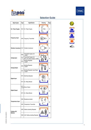
- 1. D-NR.00 00 -06-de-09/2012 1 Selection Guide Signal types Type Signification Drawing Page Ex i Power Supply 9143 Ex i Power Supply 2 Frequency Input 9146 Frequency Transmitter 3 Vibration transducer 9147 Vibration transducer 4 Analog Input 9160 Transmitter Supply Unit + HART 5 9162 Transmitter Supply Unit with Limit Value Contact + HART 9163 Isolating Repeater + HART Analog Output 9165 Isolating Repeater + HART 6 9167 Isolating Repeater Loop Power + HART Digital Input 9170 Switching Repeater 7 9172 Ex i Relay Module Digital Output 9175 9176 Binary Output 8 9172 Ex i Relay Module Temperature Input 9180 Resistance Isolator 9 9182 Temperature Transmitter Profibus DP, Modbus 9185 Feldbus Isolating Repeater 10 9186 LWL Feldbus Isolating Repeater
- 2. D-NR.00 00 -06-de-09/2012 2 Ex i Power Supply Type Ex i 9143/10-065-200-10 9143/10-099-220-10 9143/10-104-220-10 9143/10-114-200-10 9143/10-124-150-10 9143/10-156-065-10 9143/10-156-160-10 9143/10-187-050-10 9143/10-244-06-10 9143/10-065-200-20 9143/10-104-220-20 9143/10-114-200-20 9143/10-124-150-20 9143/10-156-065-20 9143/10-156-160-20 9143/10-187-050-20 9143/10-244-060-20 Function For the intrinsically safe operation of field devices e.g. transmitters... x x x x x x x x x x x x x x x x x Installation In Zone 2 & 22 x x x x x x x x x Ex i Interfaces [Zone 1 und 21] x x x x x x x x x x x x x x x x x Number of channels 1 1 1 1 1 1 1 1 1 1 1 1 1 1 1 1 1 Nominal voltage (UN) [V] 4,0…5,6 x x 8,8…9,1 x 8,7…9,5 x x 9,4…10,4 x x 9,5…11,8 x x 12,5…14,7 x x x x 14,6…17,6 x x 18,9…23,0 x x Max. Nominal current IN 15 mA 35 mA x x 40 mA x x 45 mA x x 130 mA x x 140 mA x x 160 mA x x 180 mA x x 200 mA x x x Power supply 24 V AC / DC x x x x x x x x x 85 V…230 V AC x x x x x x x x Intrinsically safe output [Ex ib] IIC / IIB x x x x x x x x x x x x x x x x x Galvanic isolation Between output and power supply x x x x x x x x x x x x x x x x x
- 3. D-NR.00 00 -06-de-09/2012 3 Frequency Transmitter Type Ex i Non-Ex i 9146/10-11-12 9146/20-11-11 9146/10-11-62 Function To monitors the speed of rotating devices like fans, centrifuges, tube extruder,... x x x Installation In Zone 2 & 22 x x x Ex i Interfaces [Zone 0 und 20] x x Number of Channels 1 2 1 Input signal Gem. EN 60947-5-6 (NAMUR) x x x Input frequency 0,001 Hz…20 kHz x x x Output 0/4 mA …20 mA x x x Limit value 2 x NO (contact per channel) x x Pulse output One NO selectable x x Power supply 24 V DC x x x Open-circuit and short-circuit Line fault detection x x x Potential free relay contact x x x Galvanic isolating Between input, output and power supply x x x
- 4. D-NR.00 00 -06-de-09/2012 4 Vibration transducer Type Ex i 9147/10-99-10s 9147/20-99-10s Function for intrinsically safe operation of vibration sensors, speed and acceleration sensors. x x Installation in Zone 2 & 22 x x Ex i Interfaces [Zone 0 und 20] x x Number of channels 1 2 Ex i Input signal Input resistance 10 kΩ x x Input signal l -0,5 ... -20 V x x Functional range 0 ... -24 V x x Output -0,5 ... -20 V x x Power supply 24 V DC x x Galvanic isolating Between input, output and power supply x x
- 5. D-NR.00 00 -06-de-09/2012 5 Transmitter Supply Unit and Isolating Repeater (AI) Type Ex i Non-Ex i 9160/13-10-11 9160/13-10-10 9160/19-10-11 9160/23-10-11 9160/23-10-10 9160/13-11-11 9160/13-11-10 9160/19-11-11 9160/19-11-10 9160/23-11-11 9160/23-11-10 9162/13-11-12 9162/13-11-14 9163/13-11-11 9163/13-10-11 9163/23-11-11 9163/23-10-11 9164/13-22-08 9164/13-22-09 9160/13-11-61 9160/19-11-61 9160/23-11-61 9162/13-11-64 Function Transmitter supply unit with HART x x x x x x x x x x x x x x x x x Isolating repeater for 4-ware Transmitter x x x x x x x x x x x x x x x x x Isolating repeater for 4-ware Transmitter with HART x x x x to integrate 4-wire transmitters with 2 wire I/O-cards x x Installation Zone 1 x x Zone 2 und 22 x x x x x x x x x x x x x x x x x x x x x x x Ex i Interfaces [Zone 0 und 20] x x x x x x x x x x x x x x x x x x x Number of channels 1 1 1 2 2 1 1 1 1 2 2 1 1 1 1 2 2 1 1 1 1 2 1 Duplicate signal x x x x Input Exi: 0/4 mA…20 mA with HART x x x x x x x x x x x x x x x x x Non Ex i: 0/4 mA…20 mA with HART x x x x 4-wire MU (Ex i Anschluss) x 4-wire MU (Ex e Anschluss) x Output A 0/4 mA…20 mA with HART x x x x x x x x x x x x x x Passive with HART x x x x x x x Output B Passive without HART x Passive with HART x x 0/4 mA…20 mA x x x 0/4 mA…20 mA with HART x x x Limit value contact 2 x NO x x x Number of wire 2-, 3 & 4-wire transmitter and mA sources x x x x x x x x x x x x x x x x x 4-wire HART transmitter x x x x SIL 2 (IEC 61508) x x x x x x x x x x x x x x x x x x x x Power supply 24 V DC x x x x x x x x x x x x x x x x x x x x x Open-circuit and short-circuit Line fault detection x x x x x x x x x x x x x x x x x fault message contact x x x x x x x x x x x x x x x x fault signal contact (LED) x x x x x x x x x x x x x x x x Galvanic isolating Between input, output x x Between input, output and power supply x x x x x x x x x x x x x x x x x x x x x
- 6. D-NR.00 00 -06-de-09/2012 6 Isolating Repeater (AO) Type Ex i Non-Ex i 9165/16-11-11 9165/16-11-10 9165/26-11-11 9165/26-11-10 9167/11-11-00 9167/21-11-00 9167/13-11-00 9167/23-11-00 9167/14-11-00 9167/24-11-00 9165/16-11-61 9165/26-11-61 9167/13-11-50 9167/23-11-50 Function Isolating repeaters are used in the intrinsically safe operation of control valves, i/p-converters or indicators.….. x x x x x x x x x x x x x x Installation In Zone 2 x x x x x x x x x x x x x x Ex i Interfaces [Zone 0 und 20] x x x x x x x x x x Number of channels 1 1 2 2 1 2 1 2 1 2 1 2 1 2 Input 0/4 mA…20 mA with HART x x x x x x x x x x x x x x Output Ex i: 0/4 mA…20 mA with HART x x x x x x x x x x Non Ex i: 0/4 mA…20 mA with HART x x x x Uo / Io / Po (15,7 V / 60 mA / 233 mW) x x Uo / Io / Po (18,8 V / 107 mA / 503 mW) x x Uo / Io / Po (25 V / 99 mA / 613 mW) x x Uo / Io / Po (25,6 V / 96 mA / 605 mW) x x x x Min. load resistance RL 150 Ω x x x x Max. load resistance RL 360 Ω x x 590 Ω x x 800 Ω x x x x SIL (IEC 61508) SIL 2 x x x x x x SIL 3 x x x x x x x x Power supply 24 V DC x x x x x x Loop power x x x x x x x x Open-circuit and short-circuit Line fault detection x x x x x x fault message contact x x x x fault signal contact (LED) x x x x x x Galvanic isolating Between input and output x x x x x x x x x x Between input, output and power supply x x x x
- 7. D-NR.00 00 -06-de-09/2012 7 Switching Repeater and Ex i Relay Module (DI) Type Ex i 9170/10-11-11 9170/11-11-13 9170/10-11-21 9170/20-10-11 9170/20-11-11 9170/21-11-13 9170/20-10-21 9170/20-11-21 9170/10-12-11 9170/10-12-21 9170/10-13-21 9170/20-12-11 9170/20-12-21 9170/11-14-11 9170/21-14-11 9170/11-14-12 9170/11-14-12- C1515 *) 9170/21-14-12 9170/21-14-12- C1515*) 9172/10-11-00 9172/20-11-00 Function For intrinsically safe operation of contacts, optocoupler outputs etc. x x x x x x x x x x x x x x x x x x x Relay Ex i activation / Non-Ex i contact x x Installation In Zone 2 x x x x x x x x x x x x x x Ex i Interfaces [Zone 0 und 20] x x x x x x x x x x x x x x x x Number of channels 1 1 1 2 2 2 2 2 1 1 1 2 2 1 2 1 1 2 2 1 2 Input intrinsically safe input [Ex ia] IIC x x x x x x x x x x x x x x x x x x x x x Output per channel 1 x Changeover (125 V / 1 A) x x x 1 x Changeover (250 V / 4 A) x x x x x 2 x Changeover (125 V / 1 A) x x x 2 x Changeover (250 V / 4 A) x x 2 x NO (125 V / 1 A) x x x 1 x Electronic (35 V/50mA) x x x x x x Transmission frequency ≤ 6 Hz x x x x x ≤ 15 Hz x x x x x x x x x x ≤ 10 kHz x x x x x x SIL 2 (IEC 61508) x x x x x x x x x x x x x x x x x x x x x Power supply 24 V DC x x x x x x x x x x x x x 110 V … 230 V x x x x x x Loop power x x Line fault transparency (LFT) x x x x Open-circuit and short-circuit Line fault detection x x x x x x x x x x x x x x x x x x x fault message contact x x x x x x x x x x x x fault signal contact (LED) x x x x x x x x x x x x x x x x x x x Galvanic isolating Between input and output x x Between input, output and power supply x x x x x x x x x x x x x x x x x x x *) only for Yokogawa ProSafe-RS I/O Modules SDV 144
- 8. D-NR.00 00 -06-de-09/2012 8 Binary Output and Ex i Relay Module (DO) Type With power supply(9175) Loop power (9176 & 9172) 9175/10-12-11 9175/20-12-11 9175/10-12-12 9175/10-14-11 9175/20-14-11 9175/10-14-12 9175/10-16-11 9175/10-16-11- C1329 9175/20-16-11 9175/20-16-11- C1329 9175/10-16-12 9176/10-12-00 9176/20-12-00 9176/10-14-00 9176/20-14-00 9176/10-15-00 9176/20-15-00 9176/10-16-00 9176/20-16-00 9176/10-17-00 9176/20-17-00 9172/11-11-00 9172/21-11-00 Function Binary output for the intrinsically safe operation of Ex i solenoid valves or indicators. x x x x x x x x x x x x x x x x x x x x x Relay for Non-Ex i Activation / Ex i Contact x x Installation in Zone 2 x x x x x x x x x x x x x x x x x x x x x x x Ex i Interface [Zone 0 und 20] x x x x x x x x x x x x x x x x x x x x x x x Number of channels 1 2 1 1 2 1 1 1 2 2 1 1 2 1 2 1 2 1 2 1 2 1 2 Intrinsically safe output [Ex ia] IIC x x x x x x x x x x x x x x x x x x x x x x x [Ex ib] IIC x x x x x x x x x x x x x x x x Ex i , 1 changeover (125 V / 4 A; 30 V / 4 A) x x Max. Output current (IA max) 29 mA x x 35 mA x x x x x x x 40 mA x x 45 mA x x x x x 60 mA x x x x x Parallel interconnection 58 mA x Parallel interconnection 70 mA x x x Parallel interconnection 80 mA x Parallel interconnection 90 mA x x Parallel interconnection 120 mA x x Internal resistance Ri 130 Ω x x x x x 150 Ω x x x x x 460 Ω x x 250 Ω x x x x x x x 320 Ω x x Parallel interconnection 65 Ω x x Parallel interconnection 75 Ω x x Parallel interconnection 125 Ω x x x Parallel interconnection 160 Ω x Parallel interconnection 230 Ω x NO-load voltage (UA) 10 V x x x x x 17,5 V x x x x x 25 V x x x x x x x x x x x SIL 2 (IEC 61508) x x x x x SIL 3 (IEC 61508) x x x x x x x x x x x x x x x x x x Power supply 24 V DC x x x x x x x x x x x Loop power x x x x x x x x x x x x Line fault transparent (LFT) x x x Open-circuit and short-circuit Line fault detection x x x x x x x x x x x fault message contact x x x x x x x x x x x fault signal contact (LED) x x x x x x x x x x x Galvanic isolating Between input and output x X**) x x X**) x x x X**) X**) x x x x x x x x x x x x x Between input, output and power supply x x X***) x X***) x x x x x***) *) only for Yokogawa ProSafe-RS I/O Modules SDV 541 **) No galvanic isolating between outputs ***) No galvanic isolating between output and power supply
- 9. D-NR.00 00 -06-de-09/2012 9 Resistance Isolator and Temperature Transmitter (TI) Type Ex i Non-Ex i 9180/10-77-11 9180/20-77-11 9180/11-77-11 9180/21-77-11 9182/10-51-11 9182/20-51-11 9182/10-59-11 9182/10-59-13 9182/10-51-13 9182/10-50-12 9182/20-50-12 9182/10-51-12 9182/10-51-14 9182/10-51-61 9182/20-51-61 9182/10-51-63 9182/10-59-63 9182/10-51-64 Function Resistance Isolator for intrinsically safe operation of Pt 100 resistance thermometer or other resistance sensors x x x x Temperature Transmitter for intrinsically safe operation of temperature sensors x x x x x x x x x x x x x x Installation In Zone 2 x x x x x x x x x x x x x x x x x x Ex i interfaces [Zone 0 und 20] x x x x x x x x x x x x x Number of channels 1 2 1 2 1 2 1 1 1 1 2 1 1 1 2 1 1 1 Sensor Ex i: Pt 100 Resistance Isolator x x Ex i: Pt 1000 Resistance Isolator x x Ex i: Most currently available sensors can be connected, thermocouples and resistance transmitters x x x x x x x x x Non Ex i: Most currently available sensors can be connected, thermocouples and resistance transmitters x x x x x Output 0/4 mA…20 mA active x x x x x x x x x 0/4 mA…20 mA passive x x x Resistance value x x x x Measurement range 18 Ω … 391 Ω x x 180 Ω … 3910 Ω x x Limit value contact (per channel) 2 x NO x x x x x Configuration PC x x x x x x x x x x x x x x DIP-switches x x x x x Power supply 24 V x x x x x x x x x x x x x x x x x x SIL 2 (IEC 61508) x x x x x x Open-circuit and short-circuit Line fault detection x x x x x x x x x x x x x x x x x x fault message contact x x x x x x x x x x x x x x x x x x fault signal contact (LED) x x x x x x x x x x x x x x x x x x Galvanic isolating Between input, output and power supply x x x x x x x x x x x x x x x x x x
- 10. D-NR.00 00 -06-de-09/2012 10 Fieldbus Isolating Repeater Type Ex i Non- Ex i 9185/11-35-10 9185/11-45-10 9185/11-46-10 9186/12-11-11 9186/15-12-11 9186/25-12-11 9185/12-45-10 9185/12-46-10 Function Fieldbus Isolating Repeater x x x Fieldbus (Bridge) x x Fibre Optic Isolating Repeater x x x Number of channels 1 1 1 2 2 1 1 1 Interface Profibus DP / Modbus RTU x x x x Ex i Profibus DP / Modbus RTU x Installation in Zone 1 x Zone 2, 22 x x x x x x x x Ex i interface [Zone 1 und 21] x x x LWL interface [Zone 0 und 20] x x x RS 485 interface [Zone 1 und 21] x Transmission speed 1,2 kbit/s...1,5 Mbit/s x x x x 9,6 kbit…1,5 Mbit/s x x x x Interface field area RS 485 IS x x x Ex op is x x RS 485 x RS 422 x x RS 422 Ex i x x Interface safe area RS 485 (X2) x x x x x RS 422 (X2) x x x RS 232 (X1) x x x x x Ex op is x Profibus-DP (X2) x x Network structure Line structure x x x Point-to-Point Structure x x Ring structure x x x Hilfsenergie 24 V UC x x x x x x x x Line fault detection x x x x x x Galvanic isolating Between input, output and power supply x x x x x x x x