Atlas Cable Cleat Data Sheet & Selection Tables
•
1 gostou•707 visualizações

Atlas cable cleats are designed to provide mechanical support and withstand short circuits for trefoil and single cable applications. They have a patented design that offers one bolt, two bolt, or framing channel fixing options. The cleats are manufactured from galvanized or stainless steel and include integral pads to protect cables during short circuits. They have passed various testing requirements for properties like axial movement, flame resistance, lateral load, and impact resistance according to the European standard for cable cleats.

Recomendados
Recomendados
Mais conteúdo relacionado
Mais procurados
Mais procurados (9)
Semelhante a Atlas Cable Cleat Data Sheet & Selection Tables
Semelhante a Atlas Cable Cleat Data Sheet & Selection Tables (20)
Mais de Thorne & Derrick International
Mais de Thorne & Derrick International (20)
Último
Último (20)
Atlas Cable Cleat Data Sheet & Selection Tables
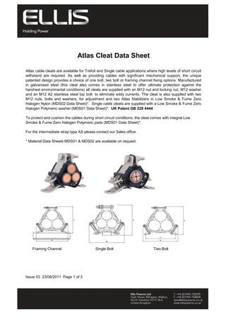
- 1. Atlas Cleat Data Sheet Atlas cable cleats are available for Trefoil and Single cable applications where high levels of short circuit withstand are required. As well as providing cables with significant mechanical support, the unique patented design provides a choice of one bolt, two bolt or framing channel fixing options. Manufactured in galvanised steel (this cleat also comes in stainless steel to offer ultimate protection against the harshest environmental conditions) all cleats are supplied with an M12 nut and locking nut, M12 washer and an M12 A2 stainless steel top bolt to eliminate eddy currents. The cleat is also supplied with two M12 nuts, bolts and washers, for adjustment and two Atlas Stabilizers in Low Smoke & Fume Zero Halogen Nylon (MDS02 Data Sheet)*. Single cable cleats are supplied with a Low Smoke & Fume Zero Halogen Polymeric washer (MDS01 Data Sheet)*. UK Patent GB 228 4444 To protect and cushion the cables during short circuit conditions, the cleat comes with integral Low Smoke & Fume Zero Halogen Polymeric pads (MDS01 Data Sheet)*. For the intermediate strap type AS please contact our Sales office. * Material Data Sheets MDS01 & MDS02 are available on request. Single Bolt Two BoltFraming Channel Issue 03 23/08/2011 Page 1 of 3 Tel: +44 (0)191 490 1547 Fax: +44 (0)191 477 5371 Email: northernsales@thorneandderrick.co.uk Website: www.cablejoints.co.uk www.thorneanderrick.co.uk
- 2. Cable Dia. Weight Range W H C P W H C W H C g mm mm mm mm mm mm mm mm mm mm mm AR2-A31-* 24-26 170 121 54 150 2xM10 144 130 54 1xM10 144 125 54 1xM10 930 AR2-A32- 26-30 170 122 54 150 2xM10 144 130 54 1xM10 144 125 54 1xM10 930 AR2-A33- 30-35 170 133 54 150 2xM10 157 141 54 1xM10 157 136 54 1xM10 970 AR2-A34- 35-40 170 134 54 150 2xM10 158 142 54 1xM10 158 137 54 1xM10 930 AR3-A35- 40-45 198 158 54 175 2xM10 185 165 54 1xM10 185 160 54 1xM10 1200 AR3-A36- 45-50 198 160 54 175 2xM10 187 167 54 1xM10 187 162 54 1xM10 1200 AR4-A37- 50-55 214 174 54 200 2xM10 204 182 54 1xM12 204 177 54 1xM12 1300 AR4-A38- 55-60 214 179 54 200 2xM10 210 187 54 1xM12 210 182 54 1xM12 1300 AR4-A39- 60-66 214 185 54 200 2xM10 217 193 54 1xM12 217 188 54 1xM12 1300 AR5-A61- 66-71 250 225 54 225 2xM10 254 225 54 1xM12 254 220 54 1xM12 1800 AR5-A62- 71-76 250 226 54 225 2xM10 255 226 54 1xM12 255 221 54 1xM12 1800 AR5-A63 76-82 250 230 54 225 2xM10 260 230 54 1xM12 260 225 54 1xM12 1800 AR8-A64- 82-92 285 250 54 225 2xM10 2100 AR8-A65- 92-102 285 250 54 225 2xM10 1900 Dimension 'C' is the cleat depth - not shown on drawing Cable Dia. Weight Range W H C P W H C W H C g mm mm mm mm mm mm mm mm mm mm mm AR2-A11-* 38-41 170 128 54 150 2xM10 144 136 54 1xM10 144 131 54 1xM10 950 AR2-A12- 41-74 170 129 54 150 2xM10 144 136 54 1xM10 144 131 54 1xM10 930 AR2-A13- 47-55 170 140 54 150 2xM10 157 147 54 1xM10 157 142 54 1xM10 940 AR2-A14- 55-63 170 141 54 150 2xM10 158 148 54 1xM10 158 143 54 1xM10 930 AR3-A15- 63-70 198 164 54 175 2xM10 185 172 54 1xM10 185 167 54 1xM10 1200 AR3-A16- 70-79 198 166 54 175 2xM10 187 173 54 1xM10 187 168 54 1xM10 1200 AR4-A17- 79-87 214 180 54 200 2xM10 204 188 54 1xM12 204 183 54 1xM12 1300 AR4-A18- 87-95 214 186 54 200 2xM10 210 193 54 1xM12 210 188 54 1xM12 1300 AR4-A19- 95-104 214 192 54 200 2xM10 217 199 54 1xM12 217 197 54 1xM12 1300 AR5-A51- 104-112 250 231 54 225 2xM10 254 231 54 1xM12 254 226 54 1xM12 1700 AR5-A52- 112-120 250 232 54 225 2xM10 255 232 54 1xM12 255 227 54 1xM12 1700 AR5-A53 120-130 250 237 54 225 2xM10 260 237 54 1xM12 260 232 54 1xM12 1700 Dimension 'C' is the cleat depth - not shown on drawing Issue 03 23/08/2011 Page 2 of 3 *To order please add fixing suffix: Two Bolt-TB Single Bolt-SB Framing Cleat-FC *To order please add fixing suffix: Two Bolt-TB Single Bolt-SB Framing Cleat-FC Fixing Holes Fixing Hole Part Number Part Number Fixing holes Fixing Hole Fixing Hole Two Bolt Single Bolt Framing Channel Dimensions Selection Table for Trefoil Cable Applications N/A N/A Selection Table for Single Cable Applications Dimensions Two Bolt Single Bolt Framing Channel N/A N/A Fixing Hole Tel: +44 (0)191 490 1547 Fax: +44 (0)191 477 5371 Email: northernsales@thorneandderrick.co.uk Website: www.cablejoints.co.uk www.thorneanderrick.co.uk
- 3. Testing Information Issue 03 23/08/2011 Page 3 of 3 Axial Movement Test 9.5 Needle Flame Test 6.5, 10.0 Resistance to Electro Mechanical Force 6.3 Atlas Cleats have been tested in line with the European Standard of 'Cable Cleats for Electrical Installations' BS EN 50368:2003. Typical results are detailed below: Properties BS EN 50368:2003 Classification Clause Units / Classification Atlas Trefoil Cable Application Test Data Atlas Single Cable Application Test Data 2000 1450 Lateral Load Test 9.2 Newtons (N) Refer to Ellis Patents for further details. 10670 Application Time (seconds) >120 >120 Temperature for Permanent Application 6.4 o C -40 to 60 -40 to 60 Refer to Ellis Patents for further details. Refer to Ellis Patents for further details. Refer to Ellis Patents for further details. Impact Resistance 6.2, 6.2.5, 9.3 Very heavy Classification (6.7kg @ 300mm) Pass Pass Cleat Type 6.1, 6.1.3 Composite - - Tel: +44 (0)191 490 1547 Fax: +44 (0)191 477 5371 Email: northernsales@thorneandderrick.co.uk Website: www.cablejoints.co.uk www.thorneanderrick.co.uk