
Recomendados
Recomendados
Mais conteúdo relacionado
Mais procurados
Mais procurados (19)
Destaque
Semelhante a Automatic welding inspection system using machine vision
Semelhante a Automatic welding inspection system using machine vision (20)
Último
Último (20)
Automatic welding inspection system using machine vision
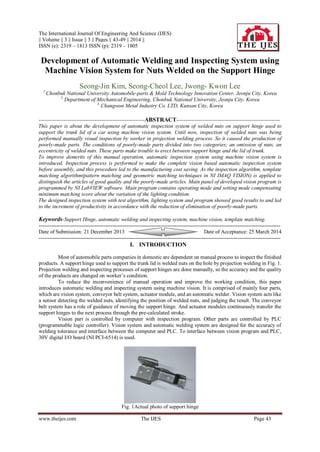
- 1. The International Journal Of Engineering And Science (IJES) || Volume || 3 || Issue || 3 || Pages || 43-49 || 2014 || ISSN (e): 2319 – 1813 ISSN (p): 2319 – 1805 www.theijes.com The IJES Page 43 Development of Automatic Welding and Inspecting System using Machine Vision System for Nuts Welded on the Support Hinge Seong-Jin Kim, Seong-Cheol Lee, Jwong- Kwon Lee 1 Chonbuk National University Automobile-parts & Mold Technology Innovation Center, Jeonju City, Korea 2, Department of Mechanical Engineering, Chonbuk National University, Jeonju City, Korea 3, Changwon Metal Industry Co. LTD, Kunsan City, Korea -----------------------------------------------------------ABSTRACT---------------------------------------------------------- This paper is about the development of automatic inspection system of welded nuts on support hinge used to support the trunk lid of a car using machine vision system. Until now, inspection of welded nuts was being performed manually visual inspection by worker in projection welding process. So it caused the production of poorly-made parts. The conditions of poorly-made parts divided into two categories; an omission of nuts, an eccentricity of welded nuts. These parts make trouble to erect between support hinge and the lid of trunk. To improve demerits of this manual operation, automatic inspection system using machine vision system is introduced. Inspection process is performed to make the complete vision based automatic inspection system before assembly, and this procedure led to the manufacturing cost saving. As the inspection algorithm, template matching algorithm(pattern matching and geometric matching techniques in NI IMAQ VISION) is applied to distinguish the articles of good quality and the poorly-made articles. Main panel of developed vision program is programmed by NI LabVIEW software. Main program contains operating mode and setting mode compensating minimum matching score about the variation of the lighting condition. The designed inspection system with test algorithm, lighting system and program showed good results to and led to the increment of productivity in accordance with the reduction of elimination of poorly-made parts. Keywords-Support Hinge, automatic welding and inspecting system, machine vision, template matching. --------------------------------------------------------------------------------------------------------------------------------------- Date of Submission: 21 December 2013 Date of Acceptance: 25 March 2014 --------------------------------------------------------------------------------------------------------------------------------------- I. INTRODUCTION Most of automobile parts companies in domestic are dependent on manual process to inspect the finished products. A support hinge used to support the trunk lid is welded nuts on the hole by projection welding in Fig. 1. Projection welding and inspecting processes of support hinges are done manually, so the accuracy and the quality of the products are changed on worker’s condition. To reduce the inconvenience of manual operation and improve the working condition, this paper introduces automatic welding and inspecting system using machine vision. It is comprised of mainly four parts, which are vision system, conveyor belt system, actuator module, and an automatic welder. Vision system acts like a sensor detecting the welded nuts, identifying the position of welded nuts, and judging the result. The conveyor belt system has a role of guidance of moving the support hinge. And actuator modules continuously transfer the support hinges to the next process through the pre-calculated stroke. Vision part is controlled by computer with inspection program. Other parts are controlled by PLC (programmable logic controller). Vision system and automatic welding system are designed for the accuracy of welding tolerance and interface between the computer and PLC. To interface between vision program and PLC, 30V digital I/O board (NI PCI-6514) is used. Fig. 1Actual photo of support hinge
- 2. Development of Automatic welding and inspecting system using… www.theijes.com The IJES Page 44 II. MECHANISM OF AUTOMATIC WELDING AND INSPECTING SYSTEM 1. Design of automatic welding and inspection system The 3D design program (Pro/E CAD) was used for the comprehensive design of automatic welding and inspection system. Firstly, object is transferred by conveyor belt. One actuator module obtains the object and then the other actuator module grips the object for welding process. For the second time, after completing welding process, the object is transferred to the inspection part using machine vision. And the other actuator grips and transfers the object on the back light box. When the object comes in the image domain, the signal is generated, and then the image is captured and saved. Saving the image, template matching is accomplished. So the product is distinguished whether the object is good or NG. Fig. 2shows the 3D view of the system and Fig. 3 explains the block diagram of control system. Fig. 2 3D model of designed system Fig. 3 Block diagram of designed system 2. Loading system A loading system used belt conveyor that is designed to supply the objects at regularly spaced intervals. It has height difference between both ends, so the objects which have height difference between both ends are able to transfer more favorably. Fig. 4 shows 3D view and actual photo of conveyor system, respectively. (a) 3D View (b) Actual photo Fig. 4 Conveyor system
- 3. Development of Automatic welding and inspecting system using… www.theijes.com The IJES Page 45 III. TRANSFER SYSTEM A transfer system has two actuator modules; one is for welding, the other is for vision inspection. A transfer system for welding plays an important role that it continuously moves the objects which are supplied through the conveyor system to welding machine. It composites three actuators along the 3-axes(x-y-z) to match the welding point accurately. And it is designed for the precise movement of the x-axis controlled by AC servo-motor. In addition, it is designed to grip the object more stably through the end effecter of the actuator. Fig. 5 shows the 3D view and actual photo of an actuator module, respectively. (b) 3D View (b) Actual photo Fig. 5 Actuator for welding process The actuator for vision inspection is designed to operate through input signal which is generated after welding process. And like the preceding, it is designed to grip the object more stably through the end effecter of the actuator. Fig. 6 shows the 3D view of the actuator for inspection using machine vision. (c) 3D View (b) Actual photo Fig. 6 Actuator for vision inspection IV. MACHINE VISION SYSTEM AND INSPECTION ALGORITHM In this study, we used analog CCD camera and durable LCD light panel. As we apply the back light condition, we designed that the computer vision system is able to recognize the object more easily. Fig. 7 shows 3D view of machine vision system, respectively. Fig. 7 3D view ofmachine vision system
- 4. Development of Automatic welding and inspecting system using… www.theijes.com The IJES Page 46 1. Machine vision system CCD Camera is mainly used in machine vision system because of its excellent durability and high speed. CCD camera achieves image data on wanted area. As input image data is sent to computer through the frame grabber, users can develop the program as image processing. Table 1 explains the specification of parts used in this study. To consistently maintain the lighting condition in vision system, back light LCD is used, which can maintain the regular intensity of light in object and its surround. Table 1 Specification of inspection system Index Specification S/W NILabVIEW & IMAQVISION H/W Camera SONY XC-ES30 - Analog CCD, 30f/sec - Resolution : 640×480 Light LCD Panel Frame Grabber NIPCI-1407 Board 2. Template matching algorithm Most of the applications of computer vision algorithms simply have to know whether the obtained image contains some previously defined sub-image or not. The sub-image is called a template and should be an ideal representation of the pattern or object which is being sought in the image. The template matching technique involves the translation of the template to every possible position in the image and the evaluation of a measure of the match between the template and the object image at that position. If the similarity measure is large enough then the object can be assumed to be present. Similarity measure is based on the Euclidean distance. Other methods computing the similarity measure are MAD(Mean Absolute Differences) and MSE(Mean Square Error). We will compute the cross-correlation function from the similarity measure. In this paper, we explain the similarity measure based on Euclidean distance method. A common measure employed when comparing the similarity of two images (e.g. the template t(i,j) and the test image g(i,j)) is the metric based on the standard Euclidean distance between two sectors, defined by: (1) The summation is evaluated for all i, such that (i-m) is a valid coordinate of the template sub-image. This definition amounts to translating the template t(i,j) to a position (m,n) along the test image and evaluating the similarity measure at that position. Alternatively, the square root in the Euclidean definition can be removed by squaring both sides of the equation. (2) Note that the summation of the last term is constant since it is a function of the template only and is evaluated over the complete domain of the template. If it is assumed that the first term is also again summing over the usual range of i and j : R(m,n) is the cross-correlation function. The template t(i-m,j-n) and the section of g(i,j) in the vicinity of (m,n) are similar when the cross-correlation is large. (3) If the assumption that the summation of g(i,j) is independent of m and n is not valid, an alternative to computing R is to compute the normalized to computing R is to compute the normalized cross-correlation N(m,n) given by: (4) The normalized cross-correlation (NCC) may be scaled so that it lies in the range 0 to 1. Thus, the cross- correlation may be redefined: (5) Fig. 8 shows the pre-defined template image and Fig.9 shows the matched image using NCC[5][6][7].
- 5. Development of Automatic welding and inspecting system using… www.theijes.com The IJES Page 47 (a) nut on the left (b)hole (c) nut on the right Fig. 8 Pre-defined template images Fig. 9 Matched image using NCC 3. Inspection program Image analysis program is done by using LabVIEW programming tool. To acquire the test image, NI VISION software is used. And template matching algorithm explained is programmed. Inspecting image size is 640×480 and computing the algorithm in ROI(region 1510 of interest) intents to save memory and reduce the operating time. One of the most important programming factors is to find the minimum matching score. We obtained the minimum matching scores using the distribution method of matching scores calculated from the correct and incorrect matching images. The dotted line denotes the decision threshold MSth for whether matching is correct or not, ⓐand ⓑdenote the regions of false rejection and false acceptance, respectively. The decision criterion should establish a decision boundary which minimizes the false rejection rate for a pre-specified false acceptance rate. Fig. 11 shows the distribution of matching scores for correct and incorrect matching. Fig. 12 shows the main panel which shows the captured picture after inspecting the support hinge. Fig. 11 Distribution of correct and incorrect matching scores Fig. 12 Main control panel of automatic welding and inspection system using machine vision In the operating mode, the image capture is triggered by the input signal and only one image is processed, but the automatic image capture is done in the setting mode. By applying the setting mode, operators can adjust the
- 6. Development of Automatic welding and inspecting system using… www.theijes.com The IJES Page 48 size of ROI and a kind of matching mode. Operating the setting mode on the developed program is explained in Fig. 13. Fig. 13 Setting mode of inspection program V. EXPERIMENTAL RESULT Generally, there are two kinds of poorly-made products having bad quality: eccentrically welded nuts on support hinge and missing nuts on support hinge. And another kind of poorly-made is the condition of eccentrically welded nuts, but there is no interference between two holes. Detecting former two types of poorly-made is solved using template matching techniques. Another problem is solved using geometric matching techniques. The geometric matching algorithm uses geometric information present in the template image as the primary features for matching. Geometric features can range from low-level features, such as edges or curves, to higher-level features, such as the geometric shapes made by the curves in the image. Every types of welded nut’s position was tested in this paper, and the test results were in Fig. 14. (a)An article of good quality (b)Omitted nuts (c)Eccentric nuts Fig. 14 Figure after image analysis (template matching) Fig. 14(a) shows that all templates are matched. There is one cross mark in the center of each hole, which has the information of the position of hole. And Fig. 14(b) shows that all nuts are omitted on the support hinge. Because matching score is less than the minimum matching score after the template matching is performed, there is no cross mark in the hole and no information about pixels position. Finally, as you can see from Fig. 14(c), one nut is eccentrically welded on support hinge. We can’t see any cross mark on the left side hole. Image processing test having different conditions was tried and the results are shown in Fig. 15. (a)An article of good quality (b)Poorly-made article (Eccentric nuts) Fig. 15 Geometric matched images
- 7. Development of Automatic welding and inspecting system using… www.theijes.com The IJES Page 49 Fig. 15(a) shows an article of good quality. There is no interference and no eccentricity between two holes. Fig. 15(b) shows poorly-made article. There is no interference between two holes, but nuts are eccentrically welded. So geometric matching is not performed. Also, there is no cross mark having the information of position. VI. CONCLUSION To detect the poorly-made conditions about finished products of support hinges, the application of template matching algorithm and geometric matching algorithm were done well and showed good results. And designed back light LCD system is most suitable for inspecting the support hinge. Through the use of the inspection system using machine vision, the followings are expected. 1) Working conditions are improved. 2) Expedient detection of the conditions of the products found to have defects. ACKNOWLEDGEMENTS This research was funded by Changwon Metal Industry Co. Ltd. and Kunsan Cluster Agency of Korea Industrial Complex Corporation. REFERENCES [1] M Ozaki, Y. Adachi, Y. Iwahori, and N. Ishii, Application of fuzzy theory to writer recognition of Chinese characters, International Journal of Modelling and Simulation, 18(2), 1998, 112-116. [2] Y. C. Lee, S. C. Lee, and S. M. Kim, Design of Vision Based Punching Machine having Serial Communication, International Conference on Control, Automation and Systems, 2005, 2430-2434. [3] S. M. Kim, J. Y. Yoon, Y. C. Lee, and S. C. Lee, Inspection System of Omission and Eccentricity of Welded Nuts using Machine Vision, International Conference on Control, Automation and Systems, 2006, 506-511. [4] R.E. Moore, Interval analysis (Englewood Cliffs, NJ: Prentice-Hall, 1966). [5] Forsyth, Ponce, Computer Vision, A modern approach (Prentice Hall, 2001). [6] R. C. Gonzalez, and R. E. Woods, Digital Image Processing (Prentice Hall, 2001). [7] Thomas Klinger, Image Processing with LabVIEW and IMAQ Vision (Prentice Hall, June 11, 2001). [8] D. J. Kang, J. E. Ha, Digital Image Processing Using Visual C++ (SciTech media, 2003). [9] J. H. Hong, Mechanical Design using Pro/Engineer (SigmaPress, 2003). [10] David Vernon, Machine Vision, Automated Visual Inspection and Robot Vision (Prentice Hall, 1991). [11] J. P. Lewis, Fast Normalized Cross-Correlation (Vision Interface, 1995). [12] Ramesh Jain, RangacharKasturi, Brian G. Schunck, MACHINE VISION (McGraw-Hill, 1998). [13] J. R. Parker, Algorithms for image processing and Computer vision (Wiley Computer Publishing, 1996).