SlideShare uma empresa Scribd logo
1 de 25
Baixar para ler offline
Seismic design and assessment of
                 Seismic design and assessment of
                   Masonry Structures
                   Masonry Structures

                            Lesson 14
                               October 2004


                                        Masonry Structures, lesson 14 slide 1


The reality of most historical centers: what is “the building”?


                                                       (Carocci et al., 1993)

                                        Masonry Structures, lesson 14 slide 2
PROGRESSIVE GROWTH                                    STOREYS ADDED TO
         IN PLAN                                         EXISTING BUILDINGS


         A: Existing cell
         B and C: Added cells
                                 (Giuffré, 1993)


                                Cells A and B
                                built after C


                                                Masonry Structures, lesson 14 slide 3


Damage in most vulnerable buildings:


      Tyipically, partial
 overturning mechanisms of
 façade walls or corner walls


                                                Masonry Structures, lesson 14 slide 4
Typical distribution of
                                      damage in historical
                                            centers.


                                Masonry Structures, lesson 14 slide 5


A strong (arguable) statement:


 Historical buildings can be thought of as
 quot;…made by an assemblage of partial structures, and
 each of them can be easily singled out. Walls,
 floors, roofs, are isostatic structures resting the one
 on the other and, at the same time, joining the one
 to the other. It can be asserted that always the
 damage affects the weakest part of the building, and
 the analysis has the task of pointing out which partquot;.
                                        A. Giuffré, 1989


                                Masonry Structures, lesson 14 slide 6
A weaker (wiser) statement:

 Although the building as a whole is a redundant
 (hyperstatic) structure, simpler subsystems can be identified,
 which make up the structure and which can be treated in
 many cases as statically determined.
 Focus is on equilibrium and on the compatibility of external
 and internal forces with the strength of each subsystem.
 First step in modelling: understand the response mechanisms
 of vulnerable subsystems.


                                     Masonry Structures, lesson 14 slide 7


Catalog of damage mechanisms due to earthquakes:

DAMAGE DUE TO INSUFFICIENT QUALITY OF
MASONRY (AS TYPICAL IN DOUBLE-LEAF WALLS
                       DOUBLE-


                                     Masonry Structures, lesson 14 slide 8
Catalog of damage mechanisms due to earthquakes:

OUT-OF-PLANE INSTABILITY OF
OUT- OF-
DOUBLE-LEAF WALLS
DOUBLE-


                                Masonry Structures, lesson 14 slide 9


Catalog of damage mechanisms due to earthquakes:

GLOBAL OVERTURNING OF FAÇADES
                      FAÇ


                                Masonry Structures, lesson 14 slide 10
Catalog of damage mechanisms due to earthquakes:
GLOBAL OVERTURNING OF FAÇADES
                      FAÇ


                                Masonry Structures, lesson 14 slide 11


Catalog of damage mechanisms due to earthquakes:
OVERTURNING OF FAÇADES
               FAÇ
CARRYING OVER CORNER “WEDGES”


                                Masonry Structures, lesson 14 slide 12
Catalog of damage mechanisms due to earthquakes:

PARTIAL OVERTURNING OF FAÇADES
                       FAÇ


                                 Masonry Structures, lesson 14 slide 13


Catalog of damage mechanisms due to earthquakes:
OVERTURNING OF FAÇADES
               FAÇ


                                 Masonry Structures, lesson 14 slide 14
Catalog of damage mechanisms due to earthquakes:
PARTIAL OVERTURNING OF
FAÇADES: EFFECT OF OPENINGS
FAÇ


                              Masonry Structures, lesson 14 slide 15


Catalog of damage mechanisms due to earthquakes:
PARTIAL OVERTURNING OF
FAÇADES: EFFECT OF OPENINGS
FAÇ


                              Masonry Structures, lesson 14 slide 16
Catalog of damage mechanisms due to earthquakes:
PARTIAL OVERTURNING OF
FAÇADES: EFFECT OF OPENINGS
FAÇ


                              Masonry Structures, lesson 14 slide 17


Catalog of damage mechanisms due to earthquakes:
DAMAGE DUE TO THRUST FROM
ROOF STRUCTURE


                              Masonry Structures, lesson 14 slide 18
Catalog of damage mechanisms due to earthquakes:
DAMAGE DUE TO THRUST FROM
ROOF STRUCTURE


                            Masonry Structures, lesson 14 slide 19


Catalog of damage mechanisms due to earthquakes:
DAMAGE DUE TO THRUST FROM
ROOF STRUCTURE


                            Masonry Structures, lesson 14 slide 20
Catalog of damage mechanisms due to earthquakes:
RIGID DIAPHRAGMS AND R.C. BEAMS
SOMETIMES NOT EFFECTIVE IN
PREVENTING DAMAGE OF WALLS


                                  Masonry Structures, lesson 14 slide 21


Catalog of damage mechanisms due to earthquakes:
LOCAL DAMAGE IN WALL –JOISTS
CONNECTIONS


                                  Masonry Structures, lesson 14 slide 22
Catalog of damage mechanisms due to earthquakes:
LOCAL DAMAGE DUE TO
POUNDING OF ADJACENT
BUILDINGS


                                      Masonry Structures, lesson 14 slide 23


 Mechanical approach to damage mechanisms: limit analysis


•Many of the collapse mechanisms are partial, in the sense that
they involve specific sub-structures or components.
•Collapse is due, most of the times, to loss of equilibrium rather
than to the exceedance of some level of stress.
•When horizontal acceleration are high enough to trigger a
mechanism, it may be assumed that the different parts can be
idealized as rigid bodies.
•The lateral force capacity of the subsystem can be related to a
corresponding acceleration.

•Static threshold resistance can be evaluated through limit
analysis and the application of the principle of virtual work.

                                      Masonry Structures, lesson 14 slide 24
Principle of virtual work

 If a system which is in equilibrium under the action of a set of
 externally applied forces is subjected to a virtual displacement
 (velocity), i.e. an infinitesimal displacement (velocity) pattern
 compatible with the system’s constraints, the total work (power)
 done by the set of forces will be zero, i.e.

 the vanishing of the work done during a virtual displacement
 is equivalent to a statement of equilibrium

  The principle of virtual work (PVW) is particularly useful when
 the structural systmem is complex, involving a number of
 interconnected bodies, in which the direct equilibration of forces
 may be difficult
                                            Masonry Structures, lesson 14 slide 25


Example of limit analysis using the PVW: out-of-plane analysis of a simple wall


                                   PVW:
                                   Ψ infinitesimal rotation of the lower body
         λP2
                                   Φ = Ψ× h1/h2 rotation of upper body
               P2
                                   λ (P1δ1x +P2δ2x )- (P1δ1y +P2δ2y +S δNy)=0
                                   λ (P1δ1x +P2δ2x )= P1δ1y +P2δ2y +S δNy
                                   Wactive= Wresisting
        λP1
               P1                  λ= (P1δ1y +P2δ 2y +Sδ Ny )/ (P1δ 1x + P2δ2x )
                                   find minimum λ
                                   δλ /dx = 0            x      λ min


                                            Masonry Structures, lesson 14 slide 26
By putting: h2 = 1 H                              ( x − 1)
                                 and       h1 =            H
                     x                                x

                   B 2 x + ( S / P )( x + 1) x
then :       λ=
                   H           x −1

 By requiring that dλ/dx = 0 we
 obtain:

              P+S
 x = 1+ 2
               S

                                                  Masonry Structures, lesson 14 slide 27


 In some simple cases it is possible to write directly equilibrium equations
 and evaluate λ without recurring to PWV:

                         Mres = Mactive(λ) = λMactive(λ=1)
                           λ = Mres /Mactive(λ=1)

                         in this case, for the two mechanisms below, equilibrium about
                         A and about B are easily written, and two different values of λ
                         will be found, λ1 and λ2.

                         The lowest of the
                         two will be the
                         “true” mechanism.


                                                  Masonry Structures, lesson 14 slide 28
Factors influencing static threshold

•geometry and restraints of mechanism
•amount, spatial distribution and nature of vertical loads
•friction forces
•forces coming from devices such as tie-rods
•compression strength of masonry


                                    Masonry Structures, lesson 14 slide 29


Geometry, restraints of mechanism, spatial distribution and
nature of vertical loads


•Geometry can be assumed on the basis of the knowledge
of the seismic behaviour of similar structures or can be
identified considering the presence of previous cracks;
•moreover, the quality of the connections between walls,
the masonry texture (brickwork), the presence of tie-rods,
the possible interactions with other parts of the building
and with adjacent buildings have to be considered.
•The definition of the geometry and restraints is also
strictly related to how vertical weigths and associated
horizontal inertia forces are transferred to the walls.


                                    Masonry Structures, lesson 14 slide 30
Friction forces


                                  Masonry Structures, lesson 14 slide 31


Friction forces


   friction along toothed crack   (De Felice and Giannini, 2001)


                                  Masonry Structures, lesson 14 slide 32
Forces coming from tie rods


                                              α0P1
                                                               P1


                                                  θ1


                                         Masonry Structures, lesson 14 slide 33


 Forces coming from tie rods


                                                                    F1


                                          α0P1
                                                          P1


                                             θ1


The effect of tie rods can be introduced as an external force whose value
depends on displacement

                                         Masonry Structures, lesson 14 slide 34
Forces coming from tie rods


                     F1
                             a*         strength of anchorage attained


                            a0*                (a)
α0P1                                                          with tie rod
                            a'0
              P1
                                        (b)

  θ1
                                  without tie rod
                                           d *=0.4 d' *
                                            u     0            d*            d'0*    d0*
                                        displacement

  The effect of tie rods can be introduced as an external force whose value
  depends on displacement

                                                     Masonry Structures, lesson 14 slide 35


   Effect of compressive strength of masonry


       (a)                                                                     (b)


                                                            SHIFTING OF
                                                               HINGE
   Wall subject to overturning::
   (a) assuming infinite (high) compression strength;
   (b) with limited (low) compression strength: centre of vertical reaction
       moves inwards
                                                     Masonry Structures, lesson 14 slide 36
More complex mechanisms

                                                            Q rs                      Qr


        Q rs                                                                      Qf
               Ts Q                                                Q fs
                    r

                                             T                     1


                                                       hs
                                                                          2                    φ
                            b                                                                           Ti
                            h
                        l

                                                                              i            α


                                         L                                    n


                            (D’Ayala and Speranza, 2002, Restrepo-Velez, 2004)

                                                               Masonry Structures, lesson 14 slide 37


                                                                                                                  Qr


                 Qr                                                                                              Qf
                                         T
                                                                                  1
                   φ
                                                      hs
                                                                                               2
    b
    h
l                                                                                                        i

                                                                                                             α
                                     L           L1                                                          n

                                L2                                                                 L1             L2


                                                                   (Restrepo-Velez, 2004)


                                                               Masonry Structures, lesson 14 slide 38
(D’Ayala and Speranza, 2002)


                                             Masonry Structures, lesson 14 slide 39


Use of rigid-body analysis for seismic assessment

 •Earlier uses of limit rigid-body limit analysis was made essentially on a
 comparative basis, to evaluate which part of the structure are most vulnerable,
 and to check the effect of strengthening techniques (e.g. insertion of tie-rods,
 of rigid diaphragms…) on out-of-plane mechanisms.


 •The general concept is to have horizontal load multipliers for out-of-plane
 mechanisms which are higher than the global base shear coefficient of the
 building, corresponding to the strength associate to in-plane response of walls.


 •A more recent approach (new Italian seismic code) proposes the use of rigid-
 body analysis within equivalent static assessment procedures which take into
 account, in an approximate way, the dynamic nature of the response.


                                             Masonry Structures, lesson 14 slide 40
Use of rigid-body analysis for seismic assessment

1. definition of a s.d.o.f. mechanism and its kinematics, by idealizing
the substructure as a set of rigid bodies which can slide/rotate,
separated from each other by fracture lines.

2. evaluation of the static horizontal multiplier of vertical weights α0
that corresponds to the static threshold resistance.

To this end, the following forces are applied to the system:
-the vertical self weights of the rigid blocks, applied at their centres of mass;
-the vertical loads carried by the walls transmitted by floors, roof, etc. ;
- a system of horizontal forces, proportional to the vertical weights, and to the
loads carried by the walls, if the corresponding inertia forces are expected to be
transferred to the walls which are part of the mechanism
- if present, external forces (e.g. from tie rods or from friction at boundaries);
- if present, internal forces (e.g. due to friction/interlocking among units).
                                               Masonry Structures, lesson 14 slide 41


Given a virtual rotation θk to the generic block k, it is possible to
establish the corresponding virtual displacements of the points of
application of all the forces along the respective directions.
The value of α0 can be obtained using the Virtual Work Principle, in
terms of displacements:
          ⎛ n             n+m         ⎞ n               o
      α 0 ⎜ ∑ Pi δ x,i + ∑ P j δ x, j ⎟ − ∑ Pi δ y,i − ∑ Fh δ h = L fi
          ⎜ i =1                      ⎟ i =1
          ⎝              j= n +1      ⎠                h =1
where
n is the number of all the dead loads (weights, vertical forces) applied to the
different rigid blocks of the mechanism,
m is the number of weight forces not directly applied to the blocks, whose
inertia forces will be transmitted to the blocks of the mechanism;
o is the number of the external forces applied to the blocks but not related to
considered masses;

                                               Masonry Structures, lesson 14 slide 42
⎛ n             n+m         ⎞ n               o
       α 0 ⎜ ∑ Pi δ x,i + ∑ P j δ x, j ⎟ − ∑ Pi δ y,i − ∑ Fh δ h = L fi
           ⎜ i =1                      ⎟ i =1
           ⎝              j= n +1      ⎠                h =1


 Pi is the generic weight force (block dead load, applied at its centroid, or other weight);
 Pj is the generic weight force, not directly applied to the blocks, whose mass generates
 seismic horizontal forces on the elements of the kinematical chain, because not
 effectively transferred to other parts of the building;
 δx,i is the horizontal virtual displacement of the point of application of Pi, assuming as
 positive the positive direction of the considered seismic action;
 δx,j is the horizontal virtual displacement of the point of application of Pj, assuming as
 positive the positive direction of the considered seismic action;
 δy,i is the vertical virtual displacement of the point of application of Pi, assuming as
 positive if upwards;
 Fh is the generic external force (absolute value), applied to the block;
 δh is the virtual displacement of the point of application of Fh , positive if opposite;
 Lfi is the work of internal forces.


                                                      Masonry Structures, lesson 14 slide 43


3. Definition of an equivalent s.d.o.f. system with the following
characteristics:
                        2
       ⎛ n +m       ⎞                         n+m
       ⎜ ∑ Pi δ x,i ⎟
       ⎜            ⎟                    α0   ∑ Pi       α 0g                     n +m
  M* = ⎝ n+m        ⎠
                                                                                   ∑ Pi
          i =1                                i =1
                                  a* =
                                   0             *
                                                     =               e* = gM* /
                                            M            e*
         g ∑ Pi δ 2
                  x,i
                                                                                   i =1

             i =1
                                      effective threshold               effective mass
      effective mass                     acceleration                        ratio


 4’. Simplified “linear” static safety check (ultimate limit state):

                     a gS ⎛       Z⎞
             a* ≥
              0           ⎜1 + 1.5 ⎟                 with q = 2.0
                      q ⎝         H⎠

                                                      Masonry Structures, lesson 14 slide 44
Non linear static methodology

4’’. Non linear static safety check (alternative to linear)

4’’a. Evaluate the evolution of the horizontal multiplier α by
progressively increasing the displacement dk of a control point, chosen
as suitable by the designer, until the horizontal multiplier reaches the
value of zero;

Note: when vertical forces are constant and horizontal forces are only
proportional to vertical weights, the relationship between α and dk is
approximately linear and can be expressed as

                        α = α 0 (1 − d k / d k ,0 )

 where dk,o is the displacement corresponding to zero horizontal force.


                                                Masonry Structures, lesson 14 slide 45


4’’b. Evaluate the displacement of the equivalent s.d.o.f. system as:


                          a*                          (a) with variable external forces
         n+m
          ∑ Pi δ x,i      a 0*
                                                      (b) linear
 *
d = dk    i =1                                (a)
                 n +m
                          a'0
         δ x,k   ∑ Pi
                 i =1
                                       (b)


                                          du*=0.4 d'0*        d*          d'0*      d0*

  an plot the a* – d* curve.

                                                Masonry Structures, lesson 14 slide 46
4’’b. The ultimate displacement du* is evaluated conventionally as the
lesser of:
- 40% of the displacement at zero force
- the displacement limit corresponding to locally incompatible conditions
(e.g. unseating of floor joists…)

   a*                          (a) with variable external forces

  a0*              (a)         (b) linear
  a'0

             (b)


               du*=0.4 d'0*   d*          d'0*     d0*

                                             Masonry Structures, lesson 14 slide 47


4’’c. Define effective secant period at 0.4 du* on capacity curve as:


                                            d s*
                               Ts* = 2π       *
                                            as


                                             Masonry Structures, lesson 14 slide 48
Use of rigid-body analysis for seismic assessment

4’’c. Calculate displacement demand ∆d with the following elastic response
spectrum, and compare with displacement capacity:

                                               Ts2 ⎛ 3 (1 + Z H )            ⎞
 Ts < 1.5T1                  ∆ d (Ts ) = a g S      ⎜                  − 0.5 ⎟
                                               4π ⎜ 1 + (1 − Ts T1 )
                                                  2                  2
                                                                             ⎟
                                                    ⎝                        ⎠
                                              1.5T1Ts ⎛          Z⎞
 1.5T1 ≤ Ts < TD             ∆ d (Ts ) =a g S         ⎜ 1.9 + 2.4 ⎟
                                                4π 2 ⎝           H⎠
                                                1.5T1TD ⎛          Z⎞
 TD ≤ Ts                     ∆ d (Ts ) =a g S           ⎜ 1.9 + 2.4 ⎟
                                                  4π ⎝
                                                     2
                                                                   H⎠

where Z is the height, with respect to ground, of the centroid of all inertial
masses involved in the mechanism
H is the total height of the building
all other parameters (ag, S, TD) are as specified in design acceleration spectra.


                                                   Masonry Structures, lesson 14 slide 49

Mais conteúdo relacionado

Mais procurados

NIST WTC 7 technical briefing 082608
NIST WTC 7 technical briefing 082608NIST WTC 7 technical briefing 082608
NIST WTC 7 technical briefing 082608Steven Olsen
 
Hysteresis models otani
Hysteresis models otaniHysteresis models otani
Hysteresis models otaniManuel Miranda
 
Lecture 6 7 Rm Shear Walls
Lecture 6 7 Rm Shear WallsLecture 6 7 Rm Shear Walls
Lecture 6 7 Rm Shear WallsTeja Ande
 
Lecture 4 5 Urm Shear Walls
Lecture 4 5 Urm Shear WallsLecture 4 5 Urm Shear Walls
Lecture 4 5 Urm Shear WallsTeja Ande
 
Seismic design and construction of retaining wall
Seismic design and construction of retaining wallSeismic design and construction of retaining wall
Seismic design and construction of retaining wallAhmedEwis13
 
Evaluation of the Seismic Response Parameters for Infilled Reinforced Concret...
Evaluation of the Seismic Response Parameters for Infilled Reinforced Concret...Evaluation of the Seismic Response Parameters for Infilled Reinforced Concret...
Evaluation of the Seismic Response Parameters for Infilled Reinforced Concret...IOSRJMCE
 
Masonry Retrofit
Masonry RetrofitMasonry Retrofit
Masonry RetrofitTeja Ande
 
Masonry Code Of Practice Amp
Masonry Code Of Practice   AmpMasonry Code Of Practice   Amp
Masonry Code Of Practice AmpTeja Ande
 
Code approaches to seismic design of masonry infiled rc frames
Code approaches to seismic design of masonry infiled rc framesCode approaches to seismic design of masonry infiled rc frames
Code approaches to seismic design of masonry infiled rc framesBinay Shrestha
 
Sesmic strengthening and evalution of multi storey building with soft storey ...
Sesmic strengthening and evalution of multi storey building with soft storey ...Sesmic strengthening and evalution of multi storey building with soft storey ...
Sesmic strengthening and evalution of multi storey building with soft storey ...SVMohtesham
 
Design of Low Rise Reinforced Concrete Buildings
Design of Low Rise Reinforced Concrete Buildings Design of Low Rise Reinforced Concrete Buildings
Design of Low Rise Reinforced Concrete Buildings Toe Myint Naing
 
2000 magenes a method for pushover analysis in seismic asesment of masonry bu...
2000 magenes a method for pushover analysis in seismic asesment of masonry bu...2000 magenes a method for pushover analysis in seismic asesment of masonry bu...
2000 magenes a method for pushover analysis in seismic asesment of masonry bu...Juan Carlos Jiménez Pacheco
 

Mais procurados (18)

NIST WTC 7 technical briefing 082608
NIST WTC 7 technical briefing 082608NIST WTC 7 technical briefing 082608
NIST WTC 7 technical briefing 082608
 
Hysteresis models otani
Hysteresis models otaniHysteresis models otani
Hysteresis models otani
 
Stability
StabilityStability
Stability
 
Lecture 6 7 Rm Shear Walls
Lecture 6 7 Rm Shear WallsLecture 6 7 Rm Shear Walls
Lecture 6 7 Rm Shear Walls
 
Lecture 4 5 Urm Shear Walls
Lecture 4 5 Urm Shear WallsLecture 4 5 Urm Shear Walls
Lecture 4 5 Urm Shear Walls
 
Seismic design and construction of retaining wall
Seismic design and construction of retaining wallSeismic design and construction of retaining wall
Seismic design and construction of retaining wall
 
Evaluation of the Seismic Response Parameters for Infilled Reinforced Concret...
Evaluation of the Seismic Response Parameters for Infilled Reinforced Concret...Evaluation of the Seismic Response Parameters for Infilled Reinforced Concret...
Evaluation of the Seismic Response Parameters for Infilled Reinforced Concret...
 
Masonry Retrofit
Masonry RetrofitMasonry Retrofit
Masonry Retrofit
 
Esfuerzo en vigas gauddy arcila
Esfuerzo en vigas gauddy arcilaEsfuerzo en vigas gauddy arcila
Esfuerzo en vigas gauddy arcila
 
Torsion in bldgs
Torsion in bldgsTorsion in bldgs
Torsion in bldgs
 
Masonry Code Of Practice Amp
Masonry Code Of Practice   AmpMasonry Code Of Practice   Amp
Masonry Code Of Practice Amp
 
Code approaches to seismic design of masonry infiled rc frames
Code approaches to seismic design of masonry infiled rc framesCode approaches to seismic design of masonry infiled rc frames
Code approaches to seismic design of masonry infiled rc frames
 
Simplified notes of calculate Wind & Snow loads based on CYS EC1
Simplified notes of calculate Wind & Snow loads based on CYS EC1Simplified notes of calculate Wind & Snow loads based on CYS EC1
Simplified notes of calculate Wind & Snow loads based on CYS EC1
 
Sesmic strengthening and evalution of multi storey building with soft storey ...
Sesmic strengthening and evalution of multi storey building with soft storey ...Sesmic strengthening and evalution of multi storey building with soft storey ...
Sesmic strengthening and evalution of multi storey building with soft storey ...
 
Strata control
Strata control Strata control
Strata control
 
DISEÑO DE PLACAS DE CONCRETO ARMADO
DISEÑO DE PLACAS DE CONCRETO ARMADODISEÑO DE PLACAS DE CONCRETO ARMADO
DISEÑO DE PLACAS DE CONCRETO ARMADO
 
Design of Low Rise Reinforced Concrete Buildings
Design of Low Rise Reinforced Concrete Buildings Design of Low Rise Reinforced Concrete Buildings
Design of Low Rise Reinforced Concrete Buildings
 
2000 magenes a method for pushover analysis in seismic asesment of masonry bu...
2000 magenes a method for pushover analysis in seismic asesment of masonry bu...2000 magenes a method for pushover analysis in seismic asesment of masonry bu...
2000 magenes a method for pushover analysis in seismic asesment of masonry bu...
 

Destaque

Lesson14 Exmpl
Lesson14 ExmplLesson14 Exmpl
Lesson14 ExmplTeja Ande
 
Ground Excited Systems
Ground Excited SystemsGround Excited Systems
Ground Excited SystemsTeja Ande
 
Base Excited Systems
Base Excited SystemsBase Excited Systems
Base Excited SystemsTeja Ande
 
Approximate Methods
Approximate MethodsApproximate Methods
Approximate MethodsTeja Ande
 
Numerical Methods
Numerical MethodsNumerical Methods
Numerical MethodsTeja Ande
 
Response Spectrum
Response SpectrumResponse Spectrum
Response SpectrumTeja Ande
 
Lecture 10 Urm Out Of Plane Walls Part 2
Lecture 10 Urm Out Of Plane Walls Part 2Lecture 10 Urm Out Of Plane Walls Part 2
Lecture 10 Urm Out Of Plane Walls Part 2Teja Ande
 
Lecture 13 Building Populations
Lecture 13 Building PopulationsLecture 13 Building Populations
Lecture 13 Building PopulationsTeja Ande
 
Lecture 11 Performance Based Evaluation
Lecture 11 Performance Based EvaluationLecture 11 Performance Based Evaluation
Lecture 11 Performance Based EvaluationTeja Ande
 
Lecture 11 s.s.iii Design of Steel Structures - Faculty of Civil Engineering ...
Lecture 11 s.s.iii Design of Steel Structures - Faculty of Civil Engineering ...Lecture 11 s.s.iii Design of Steel Structures - Faculty of Civil Engineering ...
Lecture 11 s.s.iii Design of Steel Structures - Faculty of Civil Engineering ...Ursachi Răzvan
 
Lecture 4 s.s. iii Design of Steel Structures - Faculty of Civil Engineering ...
Lecture 4 s.s. iii Design of Steel Structures - Faculty of Civil Engineering ...Lecture 4 s.s. iii Design of Steel Structures - Faculty of Civil Engineering ...
Lecture 4 s.s. iii Design of Steel Structures - Faculty of Civil Engineering ...Ursachi Răzvan
 
Lecture 3 s.s. iii Design of Steel Structures - Faculty of Civil Engineering ...
Lecture 3 s.s. iii Design of Steel Structures - Faculty of Civil Engineering ...Lecture 3 s.s. iii Design of Steel Structures - Faculty of Civil Engineering ...
Lecture 3 s.s. iii Design of Steel Structures - Faculty of Civil Engineering ...Ursachi Răzvan
 
Lecture 2 s.s. iii continuare Design of Steel Structures - Faculty of Civil E...
Lecture 2 s.s. iii continuare Design of Steel Structures - Faculty of Civil E...Lecture 2 s.s. iii continuare Design of Steel Structures - Faculty of Civil E...
Lecture 2 s.s. iii continuare Design of Steel Structures - Faculty of Civil E...Ursachi Răzvan
 
Lecture 2 s. s. iii Design of Steel Structures - Faculty of Civil Engineering...
Lecture 2 s. s. iii Design of Steel Structures - Faculty of Civil Engineering...Lecture 2 s. s. iii Design of Steel Structures - Faculty of Civil Engineering...
Lecture 2 s. s. iii Design of Steel Structures - Faculty of Civil Engineering...Ursachi Răzvan
 
Lecture 1 s.s.iii Design of Steel Structures - Faculty of Civil Engineering Iaşi
Lecture 1 s.s.iii Design of Steel Structures - Faculty of Civil Engineering IaşiLecture 1 s.s.iii Design of Steel Structures - Faculty of Civil Engineering Iaşi
Lecture 1 s.s.iii Design of Steel Structures - Faculty of Civil Engineering IaşiUrsachi Răzvan
 
Lecture 6 s.s.iii Design of Steel Structures - Faculty of Civil Engineering Iaşi
Lecture 6 s.s.iii Design of Steel Structures - Faculty of Civil Engineering IaşiLecture 6 s.s.iii Design of Steel Structures - Faculty of Civil Engineering Iaşi
Lecture 6 s.s.iii Design of Steel Structures - Faculty of Civil Engineering IaşiUrsachi Răzvan
 
Lecture 7 s.s.iii Design of Steel Structures - Faculty of Civil Engineering Iaşi
Lecture 7 s.s.iii Design of Steel Structures - Faculty of Civil Engineering IaşiLecture 7 s.s.iii Design of Steel Structures - Faculty of Civil Engineering Iaşi
Lecture 7 s.s.iii Design of Steel Structures - Faculty of Civil Engineering IaşiUrsachi Răzvan
 
An Introduction to ABAQUS CAE
An Introduction to ABAQUS CAEAn Introduction to ABAQUS CAE
An Introduction to ABAQUS CAEFawad Najam
 

Destaque (20)

Lesson14 Exmpl
Lesson14 ExmplLesson14 Exmpl
Lesson14 Exmpl
 
Ground Excited Systems
Ground Excited SystemsGround Excited Systems
Ground Excited Systems
 
Base Excited Systems
Base Excited SystemsBase Excited Systems
Base Excited Systems
 
Approximate Methods
Approximate MethodsApproximate Methods
Approximate Methods
 
Mdof
MdofMdof
Mdof
 
Sdof
SdofSdof
Sdof
 
Numerical Methods
Numerical MethodsNumerical Methods
Numerical Methods
 
Response Spectrum
Response SpectrumResponse Spectrum
Response Spectrum
 
Lecture 10 Urm Out Of Plane Walls Part 2
Lecture 10 Urm Out Of Plane Walls Part 2Lecture 10 Urm Out Of Plane Walls Part 2
Lecture 10 Urm Out Of Plane Walls Part 2
 
Lecture 13 Building Populations
Lecture 13 Building PopulationsLecture 13 Building Populations
Lecture 13 Building Populations
 
Lecture 11 Performance Based Evaluation
Lecture 11 Performance Based EvaluationLecture 11 Performance Based Evaluation
Lecture 11 Performance Based Evaluation
 
Lecture 11 s.s.iii Design of Steel Structures - Faculty of Civil Engineering ...
Lecture 11 s.s.iii Design of Steel Structures - Faculty of Civil Engineering ...Lecture 11 s.s.iii Design of Steel Structures - Faculty of Civil Engineering ...
Lecture 11 s.s.iii Design of Steel Structures - Faculty of Civil Engineering ...
 
Lecture 4 s.s. iii Design of Steel Structures - Faculty of Civil Engineering ...
Lecture 4 s.s. iii Design of Steel Structures - Faculty of Civil Engineering ...Lecture 4 s.s. iii Design of Steel Structures - Faculty of Civil Engineering ...
Lecture 4 s.s. iii Design of Steel Structures - Faculty of Civil Engineering ...
 
Lecture 3 s.s. iii Design of Steel Structures - Faculty of Civil Engineering ...
Lecture 3 s.s. iii Design of Steel Structures - Faculty of Civil Engineering ...Lecture 3 s.s. iii Design of Steel Structures - Faculty of Civil Engineering ...
Lecture 3 s.s. iii Design of Steel Structures - Faculty of Civil Engineering ...
 
Lecture 2 s.s. iii continuare Design of Steel Structures - Faculty of Civil E...
Lecture 2 s.s. iii continuare Design of Steel Structures - Faculty of Civil E...Lecture 2 s.s. iii continuare Design of Steel Structures - Faculty of Civil E...
Lecture 2 s.s. iii continuare Design of Steel Structures - Faculty of Civil E...
 
Lecture 2 s. s. iii Design of Steel Structures - Faculty of Civil Engineering...
Lecture 2 s. s. iii Design of Steel Structures - Faculty of Civil Engineering...Lecture 2 s. s. iii Design of Steel Structures - Faculty of Civil Engineering...
Lecture 2 s. s. iii Design of Steel Structures - Faculty of Civil Engineering...
 
Lecture 1 s.s.iii Design of Steel Structures - Faculty of Civil Engineering Iaşi
Lecture 1 s.s.iii Design of Steel Structures - Faculty of Civil Engineering IaşiLecture 1 s.s.iii Design of Steel Structures - Faculty of Civil Engineering Iaşi
Lecture 1 s.s.iii Design of Steel Structures - Faculty of Civil Engineering Iaşi
 
Lecture 6 s.s.iii Design of Steel Structures - Faculty of Civil Engineering Iaşi
Lecture 6 s.s.iii Design of Steel Structures - Faculty of Civil Engineering IaşiLecture 6 s.s.iii Design of Steel Structures - Faculty of Civil Engineering Iaşi
Lecture 6 s.s.iii Design of Steel Structures - Faculty of Civil Engineering Iaşi
 
Lecture 7 s.s.iii Design of Steel Structures - Faculty of Civil Engineering Iaşi
Lecture 7 s.s.iii Design of Steel Structures - Faculty of Civil Engineering IaşiLecture 7 s.s.iii Design of Steel Structures - Faculty of Civil Engineering Iaşi
Lecture 7 s.s.iii Design of Steel Structures - Faculty of Civil Engineering Iaşi
 
An Introduction to ABAQUS CAE
An Introduction to ABAQUS CAEAn Introduction to ABAQUS CAE
An Introduction to ABAQUS CAE
 

Mais de Teja Ande

Lecture 6 7 Rm Shear Walls
Lecture 6 7 Rm Shear WallsLecture 6 7 Rm Shear Walls
Lecture 6 7 Rm Shear WallsTeja Ande
 
Lecture 2 3 Compression, Condition Assess
Lecture 2 3 Compression, Condition AssessLecture 2 3 Compression, Condition Assess
Lecture 2 3 Compression, Condition AssessTeja Ande
 
Lecture 2 3 Compression, Condition Assess
Lecture 2 3 Compression, Condition AssessLecture 2 3 Compression, Condition Assess
Lecture 2 3 Compression, Condition AssessTeja Ande
 
Chapter11 Masonry
Chapter11 MasonryChapter11 Masonry
Chapter11 MasonryTeja Ande
 
Chapter12 Masonry
Chapter12 MasonryChapter12 Masonry
Chapter12 MasonryTeja Ande
 
Failures In Masonry Structures Lec 1
Failures In Masonry Structures Lec 1Failures In Masonry Structures Lec 1
Failures In Masonry Structures Lec 1Teja Ande
 
Design of Reinforced Masonry
Design of Reinforced MasonryDesign of Reinforced Masonry
Design of Reinforced MasonryTeja Ande
 

Mais de Teja Ande (7)

Lecture 6 7 Rm Shear Walls
Lecture 6 7 Rm Shear WallsLecture 6 7 Rm Shear Walls
Lecture 6 7 Rm Shear Walls
 
Lecture 2 3 Compression, Condition Assess
Lecture 2 3 Compression, Condition AssessLecture 2 3 Compression, Condition Assess
Lecture 2 3 Compression, Condition Assess
 
Lecture 2 3 Compression, Condition Assess
Lecture 2 3 Compression, Condition AssessLecture 2 3 Compression, Condition Assess
Lecture 2 3 Compression, Condition Assess
 
Chapter11 Masonry
Chapter11 MasonryChapter11 Masonry
Chapter11 Masonry
 
Chapter12 Masonry
Chapter12 MasonryChapter12 Masonry
Chapter12 Masonry
 
Failures In Masonry Structures Lec 1
Failures In Masonry Structures Lec 1Failures In Masonry Structures Lec 1
Failures In Masonry Structures Lec 1
 
Design of Reinforced Masonry
Design of Reinforced MasonryDesign of Reinforced Masonry
Design of Reinforced Masonry
 

Último

[2024]Digital Global Overview Report 2024 Meltwater.pdf
[2024]Digital Global Overview Report 2024 Meltwater.pdf[2024]Digital Global Overview Report 2024 Meltwater.pdf
[2024]Digital Global Overview Report 2024 Meltwater.pdfhans926745
 
Transforming Data Streams with Kafka Connect: An Introduction to Single Messa...
Transforming Data Streams with Kafka Connect: An Introduction to Single Messa...Transforming Data Streams with Kafka Connect: An Introduction to Single Messa...
Transforming Data Streams with Kafka Connect: An Introduction to Single Messa...HostedbyConfluent
 
How to convert PDF to text with Nanonets
How to convert PDF to text with NanonetsHow to convert PDF to text with Nanonets
How to convert PDF to text with Nanonetsnaman860154
 
Salesforce Community Group Quito, Salesforce 101
Salesforce Community Group Quito, Salesforce 101Salesforce Community Group Quito, Salesforce 101
Salesforce Community Group Quito, Salesforce 101Paola De la Torre
 
Pigging Solutions Piggable Sweeping Elbows
Pigging Solutions Piggable Sweeping ElbowsPigging Solutions Piggable Sweeping Elbows
Pigging Solutions Piggable Sweeping ElbowsPigging Solutions
 
FULL ENJOY 🔝 8264348440 🔝 Call Girls in Diplomatic Enclave | Delhi
FULL ENJOY 🔝 8264348440 🔝 Call Girls in Diplomatic Enclave | DelhiFULL ENJOY 🔝 8264348440 🔝 Call Girls in Diplomatic Enclave | Delhi
FULL ENJOY 🔝 8264348440 🔝 Call Girls in Diplomatic Enclave | Delhisoniya singh
 
Breaking the Kubernetes Kill Chain: Host Path Mount
Breaking the Kubernetes Kill Chain: Host Path MountBreaking the Kubernetes Kill Chain: Host Path Mount
Breaking the Kubernetes Kill Chain: Host Path MountPuma Security, LLC
 
Tech-Forward - Achieving Business Readiness For Copilot in Microsoft 365
Tech-Forward - Achieving Business Readiness For Copilot in Microsoft 365Tech-Forward - Achieving Business Readiness For Copilot in Microsoft 365
Tech-Forward - Achieving Business Readiness For Copilot in Microsoft 3652toLead Limited
 
Slack Application Development 101 Slides
Slack Application Development 101 SlidesSlack Application Development 101 Slides
Slack Application Development 101 Slidespraypatel2
 
Beyond Boundaries: Leveraging No-Code Solutions for Industry Innovation
Beyond Boundaries: Leveraging No-Code Solutions for Industry InnovationBeyond Boundaries: Leveraging No-Code Solutions for Industry Innovation
Beyond Boundaries: Leveraging No-Code Solutions for Industry InnovationSafe Software
 
Integration and Automation in Practice: CI/CD in Mule Integration and Automat...
Integration and Automation in Practice: CI/CD in Mule Integration and Automat...Integration and Automation in Practice: CI/CD in Mule Integration and Automat...
Integration and Automation in Practice: CI/CD in Mule Integration and Automat...Patryk Bandurski
 
#StandardsGoals for 2024: What’s new for BISAC - Tech Forum 2024
#StandardsGoals for 2024: What’s new for BISAC - Tech Forum 2024#StandardsGoals for 2024: What’s new for BISAC - Tech Forum 2024
#StandardsGoals for 2024: What’s new for BISAC - Tech Forum 2024BookNet Canada
 
How to Troubleshoot Apps for the Modern Connected Worker
How to Troubleshoot Apps for the Modern Connected WorkerHow to Troubleshoot Apps for the Modern Connected Worker
How to Troubleshoot Apps for the Modern Connected WorkerThousandEyes
 
04-2024-HHUG-Sales-and-Marketing-Alignment.pptx
04-2024-HHUG-Sales-and-Marketing-Alignment.pptx04-2024-HHUG-Sales-and-Marketing-Alignment.pptx
04-2024-HHUG-Sales-and-Marketing-Alignment.pptxHampshireHUG
 
SQL Database Design For Developers at php[tek] 2024
SQL Database Design For Developers at php[tek] 2024SQL Database Design For Developers at php[tek] 2024
SQL Database Design For Developers at php[tek] 2024Scott Keck-Warren
 
From Event to Action: Accelerate Your Decision Making with Real-Time Automation
From Event to Action: Accelerate Your Decision Making with Real-Time AutomationFrom Event to Action: Accelerate Your Decision Making with Real-Time Automation
From Event to Action: Accelerate Your Decision Making with Real-Time AutomationSafe Software
 
SIEMENS: RAPUNZEL – A Tale About Knowledge Graph
SIEMENS: RAPUNZEL – A Tale About Knowledge GraphSIEMENS: RAPUNZEL – A Tale About Knowledge Graph
SIEMENS: RAPUNZEL – A Tale About Knowledge GraphNeo4j
 
My Hashitalk Indonesia April 2024 Presentation
My Hashitalk Indonesia April 2024 PresentationMy Hashitalk Indonesia April 2024 Presentation
My Hashitalk Indonesia April 2024 PresentationRidwan Fadjar
 
Scaling API-first – The story of a global engineering organization
Scaling API-first – The story of a global engineering organizationScaling API-first – The story of a global engineering organization
Scaling API-first – The story of a global engineering organizationRadu Cotescu
 
Install Stable Diffusion in windows machine
Install Stable Diffusion in windows machineInstall Stable Diffusion in windows machine
Install Stable Diffusion in windows machinePadma Pradeep
 

Último (20)

[2024]Digital Global Overview Report 2024 Meltwater.pdf
[2024]Digital Global Overview Report 2024 Meltwater.pdf[2024]Digital Global Overview Report 2024 Meltwater.pdf
[2024]Digital Global Overview Report 2024 Meltwater.pdf
 
Transforming Data Streams with Kafka Connect: An Introduction to Single Messa...
Transforming Data Streams with Kafka Connect: An Introduction to Single Messa...Transforming Data Streams with Kafka Connect: An Introduction to Single Messa...
Transforming Data Streams with Kafka Connect: An Introduction to Single Messa...
 
How to convert PDF to text with Nanonets
How to convert PDF to text with NanonetsHow to convert PDF to text with Nanonets
How to convert PDF to text with Nanonets
 
Salesforce Community Group Quito, Salesforce 101
Salesforce Community Group Quito, Salesforce 101Salesforce Community Group Quito, Salesforce 101
Salesforce Community Group Quito, Salesforce 101
 
Pigging Solutions Piggable Sweeping Elbows
Pigging Solutions Piggable Sweeping ElbowsPigging Solutions Piggable Sweeping Elbows
Pigging Solutions Piggable Sweeping Elbows
 
FULL ENJOY 🔝 8264348440 🔝 Call Girls in Diplomatic Enclave | Delhi
FULL ENJOY 🔝 8264348440 🔝 Call Girls in Diplomatic Enclave | DelhiFULL ENJOY 🔝 8264348440 🔝 Call Girls in Diplomatic Enclave | Delhi
FULL ENJOY 🔝 8264348440 🔝 Call Girls in Diplomatic Enclave | Delhi
 
Breaking the Kubernetes Kill Chain: Host Path Mount
Breaking the Kubernetes Kill Chain: Host Path MountBreaking the Kubernetes Kill Chain: Host Path Mount
Breaking the Kubernetes Kill Chain: Host Path Mount
 
Tech-Forward - Achieving Business Readiness For Copilot in Microsoft 365
Tech-Forward - Achieving Business Readiness For Copilot in Microsoft 365Tech-Forward - Achieving Business Readiness For Copilot in Microsoft 365
Tech-Forward - Achieving Business Readiness For Copilot in Microsoft 365
 
Slack Application Development 101 Slides
Slack Application Development 101 SlidesSlack Application Development 101 Slides
Slack Application Development 101 Slides
 
Beyond Boundaries: Leveraging No-Code Solutions for Industry Innovation
Beyond Boundaries: Leveraging No-Code Solutions for Industry InnovationBeyond Boundaries: Leveraging No-Code Solutions for Industry Innovation
Beyond Boundaries: Leveraging No-Code Solutions for Industry Innovation
 
Integration and Automation in Practice: CI/CD in Mule Integration and Automat...
Integration and Automation in Practice: CI/CD in Mule Integration and Automat...Integration and Automation in Practice: CI/CD in Mule Integration and Automat...
Integration and Automation in Practice: CI/CD in Mule Integration and Automat...
 
#StandardsGoals for 2024: What’s new for BISAC - Tech Forum 2024
#StandardsGoals for 2024: What’s new for BISAC - Tech Forum 2024#StandardsGoals for 2024: What’s new for BISAC - Tech Forum 2024
#StandardsGoals for 2024: What’s new for BISAC - Tech Forum 2024
 
How to Troubleshoot Apps for the Modern Connected Worker
How to Troubleshoot Apps for the Modern Connected WorkerHow to Troubleshoot Apps for the Modern Connected Worker
How to Troubleshoot Apps for the Modern Connected Worker
 
04-2024-HHUG-Sales-and-Marketing-Alignment.pptx
04-2024-HHUG-Sales-and-Marketing-Alignment.pptx04-2024-HHUG-Sales-and-Marketing-Alignment.pptx
04-2024-HHUG-Sales-and-Marketing-Alignment.pptx
 
SQL Database Design For Developers at php[tek] 2024
SQL Database Design For Developers at php[tek] 2024SQL Database Design For Developers at php[tek] 2024
SQL Database Design For Developers at php[tek] 2024
 
From Event to Action: Accelerate Your Decision Making with Real-Time Automation
From Event to Action: Accelerate Your Decision Making with Real-Time AutomationFrom Event to Action: Accelerate Your Decision Making with Real-Time Automation
From Event to Action: Accelerate Your Decision Making with Real-Time Automation
 
SIEMENS: RAPUNZEL – A Tale About Knowledge Graph
SIEMENS: RAPUNZEL – A Tale About Knowledge GraphSIEMENS: RAPUNZEL – A Tale About Knowledge Graph
SIEMENS: RAPUNZEL – A Tale About Knowledge Graph
 
My Hashitalk Indonesia April 2024 Presentation
My Hashitalk Indonesia April 2024 PresentationMy Hashitalk Indonesia April 2024 Presentation
My Hashitalk Indonesia April 2024 Presentation
 
Scaling API-first – The story of a global engineering organization
Scaling API-first – The story of a global engineering organizationScaling API-first – The story of a global engineering organization
Scaling API-first – The story of a global engineering organization
 
Install Stable Diffusion in windows machine
Install Stable Diffusion in windows machineInstall Stable Diffusion in windows machine
Install Stable Diffusion in windows machine
 

Lesson14

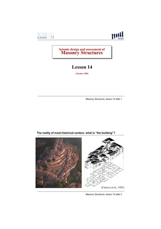
  • 1. Seismic design and assessment of Seismic design and assessment of Masonry Structures Masonry Structures Lesson 14 October 2004 Masonry Structures, lesson 14 slide 1 The reality of most historical centers: what is “the building”? (Carocci et al., 1993) Masonry Structures, lesson 14 slide 2
  • 2. PROGRESSIVE GROWTH STOREYS ADDED TO IN PLAN EXISTING BUILDINGS A: Existing cell B and C: Added cells (Giuffré, 1993) Cells A and B built after C Masonry Structures, lesson 14 slide 3 Damage in most vulnerable buildings: Tyipically, partial overturning mechanisms of façade walls or corner walls Masonry Structures, lesson 14 slide 4
  • 3. Typical distribution of damage in historical centers. Masonry Structures, lesson 14 slide 5 A strong (arguable) statement: Historical buildings can be thought of as quot;…made by an assemblage of partial structures, and each of them can be easily singled out. Walls, floors, roofs, are isostatic structures resting the one on the other and, at the same time, joining the one to the other. It can be asserted that always the damage affects the weakest part of the building, and the analysis has the task of pointing out which partquot;. A. Giuffré, 1989 Masonry Structures, lesson 14 slide 6
  • 4. A weaker (wiser) statement: Although the building as a whole is a redundant (hyperstatic) structure, simpler subsystems can be identified, which make up the structure and which can be treated in many cases as statically determined. Focus is on equilibrium and on the compatibility of external and internal forces with the strength of each subsystem. First step in modelling: understand the response mechanisms of vulnerable subsystems. Masonry Structures, lesson 14 slide 7 Catalog of damage mechanisms due to earthquakes: DAMAGE DUE TO INSUFFICIENT QUALITY OF MASONRY (AS TYPICAL IN DOUBLE-LEAF WALLS DOUBLE- Masonry Structures, lesson 14 slide 8
  • 5. Catalog of damage mechanisms due to earthquakes: OUT-OF-PLANE INSTABILITY OF OUT- OF- DOUBLE-LEAF WALLS DOUBLE- Masonry Structures, lesson 14 slide 9 Catalog of damage mechanisms due to earthquakes: GLOBAL OVERTURNING OF FAÇADES FAÇ Masonry Structures, lesson 14 slide 10
  • 6. Catalog of damage mechanisms due to earthquakes: GLOBAL OVERTURNING OF FAÇADES FAÇ Masonry Structures, lesson 14 slide 11 Catalog of damage mechanisms due to earthquakes: OVERTURNING OF FAÇADES FAÇ CARRYING OVER CORNER “WEDGES” Masonry Structures, lesson 14 slide 12
  • 7. Catalog of damage mechanisms due to earthquakes: PARTIAL OVERTURNING OF FAÇADES FAÇ Masonry Structures, lesson 14 slide 13 Catalog of damage mechanisms due to earthquakes: OVERTURNING OF FAÇADES FAÇ Masonry Structures, lesson 14 slide 14
  • 8. Catalog of damage mechanisms due to earthquakes: PARTIAL OVERTURNING OF FAÇADES: EFFECT OF OPENINGS FAÇ Masonry Structures, lesson 14 slide 15 Catalog of damage mechanisms due to earthquakes: PARTIAL OVERTURNING OF FAÇADES: EFFECT OF OPENINGS FAÇ Masonry Structures, lesson 14 slide 16
  • 9. Catalog of damage mechanisms due to earthquakes: PARTIAL OVERTURNING OF FAÇADES: EFFECT OF OPENINGS FAÇ Masonry Structures, lesson 14 slide 17 Catalog of damage mechanisms due to earthquakes: DAMAGE DUE TO THRUST FROM ROOF STRUCTURE Masonry Structures, lesson 14 slide 18
  • 10. Catalog of damage mechanisms due to earthquakes: DAMAGE DUE TO THRUST FROM ROOF STRUCTURE Masonry Structures, lesson 14 slide 19 Catalog of damage mechanisms due to earthquakes: DAMAGE DUE TO THRUST FROM ROOF STRUCTURE Masonry Structures, lesson 14 slide 20
  • 11. Catalog of damage mechanisms due to earthquakes: RIGID DIAPHRAGMS AND R.C. BEAMS SOMETIMES NOT EFFECTIVE IN PREVENTING DAMAGE OF WALLS Masonry Structures, lesson 14 slide 21 Catalog of damage mechanisms due to earthquakes: LOCAL DAMAGE IN WALL –JOISTS CONNECTIONS Masonry Structures, lesson 14 slide 22
  • 12. Catalog of damage mechanisms due to earthquakes: LOCAL DAMAGE DUE TO POUNDING OF ADJACENT BUILDINGS Masonry Structures, lesson 14 slide 23 Mechanical approach to damage mechanisms: limit analysis •Many of the collapse mechanisms are partial, in the sense that they involve specific sub-structures or components. •Collapse is due, most of the times, to loss of equilibrium rather than to the exceedance of some level of stress. •When horizontal acceleration are high enough to trigger a mechanism, it may be assumed that the different parts can be idealized as rigid bodies. •The lateral force capacity of the subsystem can be related to a corresponding acceleration. •Static threshold resistance can be evaluated through limit analysis and the application of the principle of virtual work. Masonry Structures, lesson 14 slide 24
  • 13. Principle of virtual work If a system which is in equilibrium under the action of a set of externally applied forces is subjected to a virtual displacement (velocity), i.e. an infinitesimal displacement (velocity) pattern compatible with the system’s constraints, the total work (power) done by the set of forces will be zero, i.e. the vanishing of the work done during a virtual displacement is equivalent to a statement of equilibrium The principle of virtual work (PVW) is particularly useful when the structural systmem is complex, involving a number of interconnected bodies, in which the direct equilibration of forces may be difficult Masonry Structures, lesson 14 slide 25 Example of limit analysis using the PVW: out-of-plane analysis of a simple wall PVW: Ψ infinitesimal rotation of the lower body λP2 Φ = Ψ× h1/h2 rotation of upper body P2 λ (P1δ1x +P2δ2x )- (P1δ1y +P2δ2y +S δNy)=0 λ (P1δ1x +P2δ2x )= P1δ1y +P2δ2y +S δNy Wactive= Wresisting λP1 P1 λ= (P1δ1y +P2δ 2y +Sδ Ny )/ (P1δ 1x + P2δ2x ) find minimum λ δλ /dx = 0 x λ min Masonry Structures, lesson 14 slide 26
  • 14. By putting: h2 = 1 H ( x − 1) and h1 = H x x B 2 x + ( S / P )( x + 1) x then : λ= H x −1 By requiring that dλ/dx = 0 we obtain: P+S x = 1+ 2 S Masonry Structures, lesson 14 slide 27 In some simple cases it is possible to write directly equilibrium equations and evaluate λ without recurring to PWV: Mres = Mactive(λ) = λMactive(λ=1) λ = Mres /Mactive(λ=1) in this case, for the two mechanisms below, equilibrium about A and about B are easily written, and two different values of λ will be found, λ1 and λ2. The lowest of the two will be the “true” mechanism. Masonry Structures, lesson 14 slide 28
  • 15. Factors influencing static threshold •geometry and restraints of mechanism •amount, spatial distribution and nature of vertical loads •friction forces •forces coming from devices such as tie-rods •compression strength of masonry Masonry Structures, lesson 14 slide 29 Geometry, restraints of mechanism, spatial distribution and nature of vertical loads •Geometry can be assumed on the basis of the knowledge of the seismic behaviour of similar structures or can be identified considering the presence of previous cracks; •moreover, the quality of the connections between walls, the masonry texture (brickwork), the presence of tie-rods, the possible interactions with other parts of the building and with adjacent buildings have to be considered. •The definition of the geometry and restraints is also strictly related to how vertical weigths and associated horizontal inertia forces are transferred to the walls. Masonry Structures, lesson 14 slide 30
  • 16. Friction forces Masonry Structures, lesson 14 slide 31 Friction forces friction along toothed crack (De Felice and Giannini, 2001) Masonry Structures, lesson 14 slide 32
  • 17. Forces coming from tie rods α0P1 P1 θ1 Masonry Structures, lesson 14 slide 33 Forces coming from tie rods F1 α0P1 P1 θ1 The effect of tie rods can be introduced as an external force whose value depends on displacement Masonry Structures, lesson 14 slide 34
  • 18. Forces coming from tie rods F1 a* strength of anchorage attained a0* (a) α0P1 with tie rod a'0 P1 (b) θ1 without tie rod d *=0.4 d' * u 0 d* d'0* d0* displacement The effect of tie rods can be introduced as an external force whose value depends on displacement Masonry Structures, lesson 14 slide 35 Effect of compressive strength of masonry (a) (b) SHIFTING OF HINGE Wall subject to overturning:: (a) assuming infinite (high) compression strength; (b) with limited (low) compression strength: centre of vertical reaction moves inwards Masonry Structures, lesson 14 slide 36
  • 19. More complex mechanisms Q rs Qr Q rs Qf Ts Q Q fs r T 1 hs 2 φ b Ti h l i α L n (D’Ayala and Speranza, 2002, Restrepo-Velez, 2004) Masonry Structures, lesson 14 slide 37 Qr Qr Qf T 1 φ hs 2 b h l i α L L1 n L2 L1 L2 (Restrepo-Velez, 2004) Masonry Structures, lesson 14 slide 38
  • 20. (D’Ayala and Speranza, 2002) Masonry Structures, lesson 14 slide 39 Use of rigid-body analysis for seismic assessment •Earlier uses of limit rigid-body limit analysis was made essentially on a comparative basis, to evaluate which part of the structure are most vulnerable, and to check the effect of strengthening techniques (e.g. insertion of tie-rods, of rigid diaphragms…) on out-of-plane mechanisms. •The general concept is to have horizontal load multipliers for out-of-plane mechanisms which are higher than the global base shear coefficient of the building, corresponding to the strength associate to in-plane response of walls. •A more recent approach (new Italian seismic code) proposes the use of rigid- body analysis within equivalent static assessment procedures which take into account, in an approximate way, the dynamic nature of the response. Masonry Structures, lesson 14 slide 40
  • 21. Use of rigid-body analysis for seismic assessment 1. definition of a s.d.o.f. mechanism and its kinematics, by idealizing the substructure as a set of rigid bodies which can slide/rotate, separated from each other by fracture lines. 2. evaluation of the static horizontal multiplier of vertical weights α0 that corresponds to the static threshold resistance. To this end, the following forces are applied to the system: -the vertical self weights of the rigid blocks, applied at their centres of mass; -the vertical loads carried by the walls transmitted by floors, roof, etc. ; - a system of horizontal forces, proportional to the vertical weights, and to the loads carried by the walls, if the corresponding inertia forces are expected to be transferred to the walls which are part of the mechanism - if present, external forces (e.g. from tie rods or from friction at boundaries); - if present, internal forces (e.g. due to friction/interlocking among units). Masonry Structures, lesson 14 slide 41 Given a virtual rotation θk to the generic block k, it is possible to establish the corresponding virtual displacements of the points of application of all the forces along the respective directions. The value of α0 can be obtained using the Virtual Work Principle, in terms of displacements: ⎛ n n+m ⎞ n o α 0 ⎜ ∑ Pi δ x,i + ∑ P j δ x, j ⎟ − ∑ Pi δ y,i − ∑ Fh δ h = L fi ⎜ i =1 ⎟ i =1 ⎝ j= n +1 ⎠ h =1 where n is the number of all the dead loads (weights, vertical forces) applied to the different rigid blocks of the mechanism, m is the number of weight forces not directly applied to the blocks, whose inertia forces will be transmitted to the blocks of the mechanism; o is the number of the external forces applied to the blocks but not related to considered masses; Masonry Structures, lesson 14 slide 42
  • 22. ⎛ n n+m ⎞ n o α 0 ⎜ ∑ Pi δ x,i + ∑ P j δ x, j ⎟ − ∑ Pi δ y,i − ∑ Fh δ h = L fi ⎜ i =1 ⎟ i =1 ⎝ j= n +1 ⎠ h =1 Pi is the generic weight force (block dead load, applied at its centroid, or other weight); Pj is the generic weight force, not directly applied to the blocks, whose mass generates seismic horizontal forces on the elements of the kinematical chain, because not effectively transferred to other parts of the building; δx,i is the horizontal virtual displacement of the point of application of Pi, assuming as positive the positive direction of the considered seismic action; δx,j is the horizontal virtual displacement of the point of application of Pj, assuming as positive the positive direction of the considered seismic action; δy,i is the vertical virtual displacement of the point of application of Pi, assuming as positive if upwards; Fh is the generic external force (absolute value), applied to the block; δh is the virtual displacement of the point of application of Fh , positive if opposite; Lfi is the work of internal forces. Masonry Structures, lesson 14 slide 43 3. Definition of an equivalent s.d.o.f. system with the following characteristics: 2 ⎛ n +m ⎞ n+m ⎜ ∑ Pi δ x,i ⎟ ⎜ ⎟ α0 ∑ Pi α 0g n +m M* = ⎝ n+m ⎠ ∑ Pi i =1 i =1 a* = 0 * = e* = gM* / M e* g ∑ Pi δ 2 x,i i =1 i =1 effective threshold effective mass effective mass acceleration ratio 4’. Simplified “linear” static safety check (ultimate limit state): a gS ⎛ Z⎞ a* ≥ 0 ⎜1 + 1.5 ⎟ with q = 2.0 q ⎝ H⎠ Masonry Structures, lesson 14 slide 44
  • 23. Non linear static methodology 4’’. Non linear static safety check (alternative to linear) 4’’a. Evaluate the evolution of the horizontal multiplier α by progressively increasing the displacement dk of a control point, chosen as suitable by the designer, until the horizontal multiplier reaches the value of zero; Note: when vertical forces are constant and horizontal forces are only proportional to vertical weights, the relationship between α and dk is approximately linear and can be expressed as α = α 0 (1 − d k / d k ,0 ) where dk,o is the displacement corresponding to zero horizontal force. Masonry Structures, lesson 14 slide 45 4’’b. Evaluate the displacement of the equivalent s.d.o.f. system as: a* (a) with variable external forces n+m ∑ Pi δ x,i a 0* (b) linear * d = dk i =1 (a) n +m a'0 δ x,k ∑ Pi i =1 (b) du*=0.4 d'0* d* d'0* d0* an plot the a* – d* curve. Masonry Structures, lesson 14 slide 46
  • 24. 4’’b. The ultimate displacement du* is evaluated conventionally as the lesser of: - 40% of the displacement at zero force - the displacement limit corresponding to locally incompatible conditions (e.g. unseating of floor joists…) a* (a) with variable external forces a0* (a) (b) linear a'0 (b) du*=0.4 d'0* d* d'0* d0* Masonry Structures, lesson 14 slide 47 4’’c. Define effective secant period at 0.4 du* on capacity curve as: d s* Ts* = 2π * as Masonry Structures, lesson 14 slide 48
  • 25. Use of rigid-body analysis for seismic assessment 4’’c. Calculate displacement demand ∆d with the following elastic response spectrum, and compare with displacement capacity: Ts2 ⎛ 3 (1 + Z H ) ⎞ Ts < 1.5T1 ∆ d (Ts ) = a g S ⎜ − 0.5 ⎟ 4π ⎜ 1 + (1 − Ts T1 ) 2 2 ⎟ ⎝ ⎠ 1.5T1Ts ⎛ Z⎞ 1.5T1 ≤ Ts < TD ∆ d (Ts ) =a g S ⎜ 1.9 + 2.4 ⎟ 4π 2 ⎝ H⎠ 1.5T1TD ⎛ Z⎞ TD ≤ Ts ∆ d (Ts ) =a g S ⎜ 1.9 + 2.4 ⎟ 4π ⎝ 2 H⎠ where Z is the height, with respect to ground, of the centroid of all inertial masses involved in the mechanism H is the total height of the building all other parameters (ag, S, TD) are as specified in design acceleration spectra. Masonry Structures, lesson 14 slide 49