Thomas de Jesus' Final Project Presentation
•
0 likes•882 views

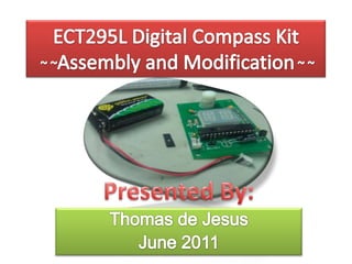
This is the slideshow I displayed when I gave my final presentation at DeVry University. It was for a digital handheld compass circuit that was modified mid-semester to display arrows.
![Introdutcion What is it? ,[object Object]](data:image/gif;base64,R0lGODlhAQABAIAAAAAAAP///yH5BAEAAAAALAAAAAABAAEAAAIBRAA7)
Recommended
More Related Content
What's hot
What's hot (20)
Viewers also liked
Viewers also liked (15)
Similar to Thomas de Jesus' Final Project Presentation
Similar to Thomas de Jesus' Final Project Presentation (20)
Recently uploaded
Recently uploaded (20)
Thomas de Jesus' Final Project Presentation
- 1. ECT295L Digital Compass Kit ~ ~Assembly and Modification~ ~ Presented By: Thomas de Jesus June 2011
- 4. 9 volt dc device
- 6. Dinsmore 1490 EMF Sensor
- 8. PIC16F72 CMOS FLASH With Analog to Digital Converter
- 10. Uses internal program with sensor to determine geographical orientation
- 11. Microcontroller outputs binary form to light LED segments
- 14. Inspected Parts for damage… OK!
- 16. Grouped in Sets of three
- 17. Spaced at 90° intervals
- 18. Tightly Spaced Together!No Room for Error!
- 19. Week 2 Installing the 1490 Compass Sensor Module: Post Installation: One Visible Bridge Easily Repaired Using De-Soldering Braid Testing for Un-Seen Bridges: Expected = Infinite Ω (Open) Red Lead Test Source Black Lead Test Source Measured = OL (Open)
- 20. Week 2 Installing the 1490 Compass Sensor Module: Post Installation: One Visible Bridge Easily Repaired Using De-Soldering Braid Reversing the leads: Expected = 290kΩ - 300kΩ Measured = 295kΩ (Approx.) Red Lead Test Source Black Lead Test Source Good Installation!
- 21. Week 3 Completing Assembly and Giving Life!
- 22. Week 3 Programming The Way! Removed any existing Microcontrollers Aligned Compass Data Header with Programming Board J5 header
- 23. Week 3 Programming The Way! First Stage Assembly = Success!
- 24. Week 4 Understanding the FlowCode
- 25. Week 4 = E PORT B = 10101101 = 173 PORT C = 10000000 = 128 (FIRST_D_x = Left Digit) (SECOND_D_x = Right Digit) Variables Affecting Display EAST (E)
- 26. Week 5 Hardware and Software Modifications:
- 27. Week 5 Hardware Modifications: Added male/female power-connector to V+/V- Added wire jumpers to close connections from the IC pins to the display LED-Segment pins: WHITE = IC Pin 13 (C2) to Display Pin 15 (Segment J) RED = IC Pin 11 (C0) to Display Pin 14 (Segment K) YELLOW = IC Pin 14 (C3) to Display Pin 4 (Segment M)
- 28. Week 6 Software Modifications: FIRST_D_1 = Port B0-7 FIRST_D_2 = Port C0-7
- 29. Week 6 Software Modifications:
- 31. AWESOME!
- 32. Week 6 Modifications Complete!
- 33. ~fin~