SlideShare a Scribd company logo
1 of 222
Download to read offline
www.Vidyarthiplus.com

Unit-1
AIRCRAFT GAS TURBINES
Impulse and reaction blading of gas turbines – Velocity triangles and power output – Elementary
theory – Vortex theory – Choice of blade profile, pitch and chord – Estimation of stage
performance – Limiting factors in gas turbine design- Overall turbine performance – Methods of
blade cooling – Matching of turbine and compressor – Numerical problems.

Axial and radial flow turbines
As with the compressor, there are two basic types of turbine—radial flow and axial flow. The
vast majority of gas turbines employ the axial flow turbine.
The radial turbine can handle low mass flows more efficiently than the axial flow machine and
has been widely used in the cryogenic industry as a turbo-expander, and in turbochargers for
reciprocating engines. Although for all but the lowest powers the axial flow turbine is normally
the more efficient, when mounted back-to-back with a centrifugal compressor the radial turbine
offers the benefit of a very short and rigid rotor. This configuration is eminently suitable for gas
turbines where compactness is more important than low fuel consumption. Auxiliary power units
for aircraft (APUs), generating sets of up to 3 MW, and mobile power plants are typical
applications.

Impulse and Reaction Turbine

www.Vidyarthiplus.com

Work can be extracted from a gas at a higher inlet pressure to the lower back pressure by
allowing it to flow through a turbine. In a turbine as the gas passes through, it expands. The work
done by the gas is equivalent to the change of its enthalpy.
It is a well known fact that the turbines operate on the momentum principle. Part of the energy of
the gas during expansion is converted into kinetic energy in the flow nozzles. The gas leaves
these stationary nozzles at a relatively higher velocity. Then it is made to impinge on the blades
over the turbine rotor or wheel. Momentum imparted to the blades turns the wheel. Thus, the two
primary parts of the turbine are,
(i) The stator nozzles, and
(ii) the turbine rotor blades.
Normally a turbine stage is classified as
(i) an impulsion stage, and
(ii) a reaction stage
An impulse stage is characterized by the expansion of the gas which occurs only in the stator
nozzles. The rotor blades act as directional vanes to deflect the direction of the flow. Further,
they convert the kinetic energy of the gas into work by changing the momentum of the gas more
or less at constant pressure.
A reaction stage is one in which expansion of the gas takes place both in the stator and in the
rotor.
The function of the stator is the same as that in the impulse stage, but the function in the
rotor is two fold.
(i) the rotor converts the kinetic energy of the gas into work, and
(ii) contributes a reaction force on the rotor blades.
The reaction force is due to the increase in the velocity of the gas relative to the blades. This
results from the expansion of the gas during its passage through the rotor.

A Single Impulse Stage
Impulse machines are those in which there is no change of static or pressure head of the fluid in
the rotor. The rotor blades cause only energy transfer and there is no energy transformation. The
energy transformation from pressure or static head to kinetic energy or vice versa takes place in
fixed blades only. As can be seen from the below figure that in the rotor blade passage of an
impulse turbine there is no acceleration of the fluid, i.e., there is no energy transformation.

www.Vidyarthiplus.com

Hence, the chances are greater for separation due to boundary layer growth on the blade surface.
Due to this, the rotor blade passages of the impulse machine suffer greater losses giving lower
stage efficiencies.
The paddle wheel, Pelton wheel and Curtis stem turbine are some examples of impulse
machines.

www.Vidyarthiplus.com

A Single Reaction Stage
The reaction stages are those, in which, changes in static or pressure head occur both in the rotor
and stator blade passages. Here, the energy transformation occurs both in fixed as well as
moving blades. The rotor experiences both energy transfer as well as energy transformation.
Therefore, reaction turbines are considered to be more efficient. This is mainly due to continuous
acceleration of flow with lower losses.

The degree of reaction of a turbomachine stage may be defined as the ratio of the static or
pressure head change occurring in the rotor to the total change across the stage.
Note: Axial-flow turbine with 50% reaction have symmetrical blades in their rotor and stators. It
may be noted that the velocity triangles at the entry and exit of a 50% reaction stage are also
symmetrical.

www.Vidyarthiplus.com

Velocity Triangles of a Single Stage Machine
The flow geometry at the entry and exit of a turbomachine stage is described by the velocity
triangles at these stations. The velocity triangles for a turbomachine contain the following three
components.
1. The peripheral / whirl / tangential velocity (u) of a rotor blades
2. The absolute velocity (c ) of the fluid and
3. The relative velocity (w or v) of the fluid
These velocities are related by the following well-known vector equation.

This simple relation is frequently used and is very useful in drawing the velocity triangles
for turbomachines.

www.Vidyarthiplus.com

The notation used here to draw velocity triangles correspond to the x-y coordinates; the
suffix (a or α) identifies components in the axial direction and suffix (t) refers to
tangential direction. Air angles in the absolute system are denoted by alpha (α), where as
those in the relative system are represented by beta (β).

Since the stage is axial, the change in the mean diameter between its entry and exit can be
neglected. Therefore, the peripheral or tangential velocity (u) remains constant in the velocity
triangles.
It can be proved from the geometry that
ct2 + ct3 = wt2 + wt3
It is often assumed that the axial velocity component remains constant through the stage. For
such condition,
ca = ca1 = ca2 = ca3

www.Vidyarthiplus.com

For constant axial velocity yields a useful relation,
tan α2 + tan α3 = tan β2 + tan β3

Expression for Work Output
Though force and torque are exerted on both stationary and moving blades alike, work can only
be done on the moving rotor blades. Thus the rotor blades transfer energy from the fluid to the
shaft. The stage work in an axial turbine (u3 = u2 = u) can be written as,
W = u2 ct2 – u3ct3
= u{ct2- (-ct3)}
= u(ct2-ct3)
{Note: Usually this equation will be written with a minus sign between ct2 and ct3. Whenever this
is written with a plus sign it is implied that ct3 is negative}
This equation can also be expressed in another form,

 ct 2 ct 3 
W = u 
+

u 
 u
2

c 
The first term  t 2  in the bracket depends on the nozzle or fixed angle (α2) and the ratio
 u 
u
c 
. The contribution of the second term  t 3  to the work is generally small. It is also
c2
 u 
observed that the kinetic energy of the fluid leaving the stage is greater for larger values of ct3.
The leaving loss from the stage is minimum when ct3 = 0, i.e., when the discharge from the stage
is axial (c3 = ca3). However, this condition gives lesser stage work as can be seen from the above
two equations.

σ =

www.Vidyarthiplus.com

Blade loading and Flow coefficients
Performance of turbomachines are characterized by various dimensionless parameters. For
example, loading coefficient (ψ) and the flow coefficient (Ф) have been defined as,

W
Ψ= 2
u
c
φ = a
u
Since the work, W in the above equation is frequently referred to as the blade or stage work, the
coefficient, ψ would also be known as the blade or stage loading coefficient.
For constant axial velocity (ca), it can be shown that
Ψ = Ф(tan α2 + tan α3) = Ф(tan β2 + tan β3)
The Ф – ψ plots are useful in comparing the performances of various stages of different sizes and
geometries.

Blade and Stage efficiencies
Even though the blade and stage work (outputs) are the same, the blade and the stage efficiencies
need not be equal. This is because the energy inputs to the rotor blades and the stage (fixed blade
ring plus the rotor) are different. The blade efficiency is also known as the utilization factor (ε)
which is an index of the energy utilizing capability of the rotor blades. Thus,
ε = ηb
= Rotor blade work / Energy supplied to the rotor blades
= W / Erb
W = u2 ct2 + u3 ct3

=

1 2 2 1 2
1 3
2
2
c 2 − c3 + u 2 − u 3 + w3 − w2
2
2
2

(

)

(

)

(

)

The energy supplied to the rotor blades is the absolute kinetic energy in the jet at the entry plus
the kinetic energy change within the rotor blades.

www.Vidyarthiplus.com

Erb =

1 2 1 2
1 3
2
2
c2 + w3 − w2 + u2 − u3
2
2
2

(

)

(

)

For axial machines, u = u2 = u3

ε = ηb =

(c

2
2

) (
(

2
2
2
− c3 + w3 − w2
2
2
2
c 2 + w3 − w2

)

)

Maximum utilization factor for a single impulse stage.

u (ct 2 + ct 3 )
ε=
1 2
c2
2
After rearranging the terms, we have

η b = ε = 4 (σ sin α 2 − σ 2 )
This shows that the utilization factor is a function of the blade-to-gas speed ratio and the nozzle
angle.

www.Vidyarthiplus.com

Elementary theory of axial flow turbine

Fig.7.2 Typical representations of velocity triangles

www.Vidyarthiplus.com

The above Figures show the velocity triangles for one axial flow turbine stage and the
nomenclature employed. The gas enters the row of nozzle blades (These are also known as 'stator
blades' and 'nozzle guide vanes') with a static pressure and temperature, P1, T1 and a velocity C1
is expanded to P2,T2 and leaves with an increased velocity C2 at an angle α2. The rotor blade inlet
angle will be chosen to suit the direction β2 of the gas velocity V2 relative to the blade at inlet.
β2and V2 are found by vectorial subtraction of the blade speed U from the absolute velocity C2.
After being deflected, and usually further expanded, in the rotor blade passages, the gas leaves at
P3, T3 with relative velocity V3 at angle β3. Vectorial addition of U yields the magnitude and
direction of the gas velocity at exit from the stage, C3 and α3. α3 is known as the swirl angle.

dimensional effects.

www.Vidyarthiplus.com

Vortex theory
It was pointed out earlier that the shape of the velocity triangles must vary from root to tip of the blade
because the blade speed U increases with radius. Another reason is that the whirl component in the flow
at outlet from the nozzles causes the static pressure and temperature to vary across the annulus. With a
uniform pressure at inlet, or at least with a much smaller variation because the whirl component is
smaller, it is clear that the pressure drop across the nozzle will vary giving rise to a corresponding
variation in efflux velocity C2. Twisted blading designed to take account of the changing gas angles is
called vortex blading.
It has been common steam turbine practice, except in low-pressure blading where the blades are
very long, to design on conditions at the mean diameter, keep the blade angles constant from root to tip,
and assume that no additional loss is incurred by the variation in incidence along the blade caused by the
changing gas angles. Comparative tests have been conducted by the earlier researchers on a single-stage
gas turbine of radius ratio 1-37, using in turn blades of constant angle and vortex blading. The results
showed that any improvement in efficiency obtained with vortex blading was within the margin of
experimental error. This contrasts with similar tests on a 6-stage axial compressor, by another researcher,
which showed a distinct improvement from the use of vortex blading. This was, however, not so

much an improvement in efficiency (of about 1-5 per cent) as in the delay of the onset of surging
which of course does not arise in accelerating flow. It appears, therefore, that steam turbine
designers have been correct in not applying vortex theory except when absolutely necessary at
the LP end. They have to consider the additional cost of twisted blades for the very large number
of rows of blading required, and they know that the Rankine cycle is relatively insensitive to
component losses. Conversely, it is not surprising that the gas turbine designer, struggling to
achieve the highest possible component efficiency, has consistently used some form of
vortex blading which it is felt intuitively must give a better performance however small.
Vortex theory has been outlined earlier by Cohen and others where it was shown that if
the elements of fluid are to be in radial equilibrium, an increase in static pressure from
root to tip is necessary whenever there is a whirl component of velocity. Figure 7.8 shows
(see below) why the gas turbine designer cannot talk of impulse or 50 per cent reaction stages.
The proportion of the stage pressure or temperature drop which occurs in the rotor must increase
from root to tip. Although Fig. 7.8 refers to a single-stage turbine with axial inlet velocity and no
swirl at outlet, the whirl component at inlet and outlet of a repeating stage will be small
compared with CW2- the reaction will therefore still increase from root to tip, if somewhat less
markedly.

www.Vidyarthiplus.com

Choice of blade profile, pitch and chord
The next step is to choose stator and rotor blade shapes which will accept the gas incident upon
the leading edge, and deflect the gas through the required angle with the minimum loss. An
overall blade loss coefficient Y (or A) must account for the following sources of friction loss.
(a)

Profile loss—associated with boundary layer growth over the blade profile (including
separation loss under adverse conditions of extreme angles of incidence or high inlet
Mach number).

(b)

Annulus loss—associated with boundary layer growth on the inner and outer walls of the
annulus.

(c)

Secondary flow loss—arising from secondary flows which are always present when a
wall boundary layer is turned through an angle by an adjacent curved surface.

(d)

Tip clearance loss—near the rotor blade tip the gas does not follow the intended path,
fails to contribute its quota of work output, and interacts with the outer wall boundary
layer.

The profile loss coefficient Yp is measured directly in cascade tests similar to those described for
compressor blading. Losses (b) and (c) cannot easily be separated, and they are accounted for by
a secondary loss coefficient Ys.

www.Vidyarthiplus.com

The tip clearance loss coefficient, which normally arises only for rotor blades, will be denoted by
Yk. Thus the total loss coefficient Y comprises the accurately measured two-dimensional loss Yp,
plus the three-dimensional loss (Ys+Yk) which must be deduced from turbine stage test results.
All that is necessary for our present purpose for finding the choice of blade profile is limited to
the knowledge of the sources of loss.

Figure 7.11 shows a conventional steam turbine blade profile constructed from circular arcs and
straight lines. Gas turbines have until recently used profiles closely resembling this, although
specified by aerofoil terminology.

www.Vidyarthiplus.com

Note that the blade profile will be completely determined when (a) the pitch/width ratio (s/w) is
established, and (b) both the camber line angle α' and blade thickness/pitch ratio have been
calculated for various values of x between 0 and 1.

www.Vidyarthiplus.com

Turbine Performance
The performance of turbine is limited principally by two factors: compressibility and
stress. Compressibility limits the mass flow that can pass through a given turbine and, stress
limits the wheel speed U. The work per stage depends on the square of the wheel speed.
However, the performance of the engine depends very strongly on the maximum temperature. Of
course, as the maximum temperature increases, the allowable stress level diminishes; hence in
the design of the engine there must be a compromise between maximum temperature and
maximum rotor tip speed U.
For given pressure ratio and adiabatic efficiency, the turbine work per unit mass is proportional
to the inlet stagnation temperature. Since, in addition, the turbine work in a jet or turboshaft
engine is commonly two or three times the useful energy output of the engine, a 1% increase in
turbine inlet temperature can produce a 2% or 3% increase in engine output. This considerable
advantage has supplied the incentive for the adoption of fairly elaborate methods for cooling the
turbine nozzle and rotor blades.

Estimation of stage performance
The last step in the process of arriving at the preliminary design of a turbine stage is to check
that the design is likely to result in values of nozzle loss coefficient and stage efficiency which
were assumed at the outset. If not, the design calculations may be repeated with more probable
values of loss coefficient and efficiency. When satisfactory agreement has been reached, the
final design may be laid out on the drawing board and accurate stressing calculations can be
performed. Before proceeding to describe a method of estimating the design point performance
of a stage, however, the main factors limiting the choice of design, which we have noted during
the course of the worked example, will be summarized. The reason we considered a turbine for a
turbojet engine was simply that we would thereby be working near those limits to keep size and
weight to a minimum. The designer of an industrial gas turbine has a somewhat easier task: he
will be using lower temperatures and stresses to obtain a longer working life, and this means
lower mean blade speeds, more stages, and much less stringentaerodynamic limitations. A power
turbine, not mechanically coupled to the gas generator, is another case where much less difficulty
will be encountered in arriving at a satisfactory solution. The choice of gear ratio between the
power turbine and driven component is normally at the disposal of the turbine designer, and thus
the rotational speed can be varied to suit the turbine, instead of the compressor as we have
assumed here.

www.Vidyarthiplus.com

www.Vidyarthiplus.com

The cooled turbine

Figure 7.29 illustrates the methods of blade cooling that have received serious attention and
research effort. Apart from the use of spray cooling for thrust boosting in turbojet engines, the
liquid systems have not proved to be practicable. There are difficulties associated with

www.Vidyarthiplus.com

channelling the liquid to and from the blades—whether as primary coolant for forced convection
or free convection open thermosyphon systems, or as secondary coolant for closed thermosyphon
systems. It is impossible to eliminate corrosion or the formation of deposits in open systems, and
very difficult to provide adequate secondary surface cooling area at the base of the blades for
closed systems. The only method used successfully in production engines has been internal,
forced convection, air cooling. With 1-5-2 per cent of the air mass flow used for cooling per
blade row, the blade temperature can be reduced by between 200 and 300 °C. Using current
alloys, this permits turbine inlet temperatures of more than 1650 К to be used. The blades are
either cast, using cores to form the cooling passages, or forged with holes of any desired shape
produced by electrochemical or laser drilling.

Figure 7.30 shows the type of turbine rotor blade introduced in the 1980s. The next step forward
is likely to be achieved by transpiration cooling, where the cooling air is forced through a porous
blade wall. This method is by far the most economical in cooling air, because not only does it
remove heat from the wall more uniformly, but the effusing layer of air insulates the outer
surface from the hot gas stream and so reduces the rate of heat transfer to the blade. Successful
application awaits further development of suitable porous materials and techniques of blade
manufacture. We are here speaking mainly of rotor blade cooling because this presents the most
difficult problem. Nevertheless it should not be forgotten that, with high gas temperatures,
oxidation becomes as significant a limiting factor as creep, and it is therefore equally important
to cool even relatively unstressed components such as nozzle blades and annulus walls.

www.Vidyarthiplus.com

Figure 7.31 (a) illustrates the principal features of nozzle blade cooling. The air is introduced
in such a way as to provide jet impingement cooling of the inside surface of the very hot leading
edge. The spent air leaves through slots or holes in the blade surface (to provide some film
cooling) or in the trailing edge.

FIG. 7.31 (a) Turbine nozzle cooling [(b) courtesy Rolls-Royce]

www.Vidyarthiplus.com

www.Vidyarthiplus.com

Figure 7.35: Shows a typical temperature distribution at the mid-span of
a blade designed to operate with Tg= 1500 К and Tсг = 320 К.

It may be noted that the final design calculation for a cooled blade will involve an estimation of
the two-dimensional temperature distribution over the blade cross-section at several values of
l/L. Finite difference methods are used to solve the differential equations, and conduction within
the blade is taken into account. Figure 7.35 shows a typical temperature distribution at the midspan of a blade designed to operate with Tg= 1500 К and Гсг = 320 К. It emphasizes one of the
main problems of blade cooling, i.e. that of obtaining adequate cooling at the trailing edge.
Finally, an estimation will be made of the thermal stresses incurred with due allowance for
redistribution of stress by creep: with cooled blades the thermal stresses can dominate the gas
bending stresses and be comparable with the centrifugal tensile stresses.
Finally, mention must be made of an alternative approach to the high- temperature turbine—the
use of ceramic materials which obviates the need for elaborate cooling passages. Much effort has
been expended on the development of silicon nitride and silicon carbide materials for small
turbine rotors (both axial and radial) in which it would be difficult to incorporate cooling
passages. Adequate reliability and life are difficult to achieve, but demonstrator engines have
been ran for short periods. Ceramic rotor blades are being investigated for use in stationary gas
turbines for powers up to about 5 MW, and experimental trials are expected in the late 1990s.
The use of ceramic turbines in production engines, however, remains an elusive goal three
decades after optimistic forecasts about their introduction.

Blade Cooling
Blade cooling is the most effective way of maintaining high operating temperatures making use
of the available material. Blade cooling may be classified based on the cooling site as external
cooling and internal cooling. Another classification based on the cooling medium is liquid
cooling and air cooling.

www.Vidyarthiplus.com

External Cooling
The external surface of the gas turbine blade is cooled by making use of compressed air from the
compressor.
Other methods of external cooling are film cooling and transpiration cooling.
Internal Cooling
Internal cooling of blades is achieved by passing air or liquid through internal cooling passages
from hub towards the blade tip. The cooling of the blades is achieved by conduction and
convection.
Hollow blades can also be manufactured with a core and internal cooling passage. Based on the
cooling medium employed, blade cooling may be classified into liquid cooling and air cooling.

Requirements for Efficient Blade Cooling
In a conventional cooled blade, cooling is obtained due to convection by passing cooling air
through internal passages within the blade. The success in obtaining the large reduction in metal
temperature at the expense of a small quantity of cooling flow is governed by the skill in
devising and machining the cooling passages. Because the internal cooling relies on the cooling
air scrubbing against the cooling surface, the internal surface area must be large and the velocity
of the cooling air must be high. This implies that the cross-sectional flow area of the passage
must be small.
The design of the blade internal geometry for cooling is more complex because of the various
aerodynamic, heat transfer, stress and mechanical design criteria that must be satisfied. The most
successful designs have incorporated radial passages through which cooling air passes, escaping
at the tip.

The radial flow turbine
In a radial flow turbine, gas flow with a high tangential velocity is directed inwards and leaves
the rotor with as small a whirl velocity as practicable near the axis of rotation. The result is that
the turbine looks very similar to the centrifugal compressor, but with a ring of nozzle vanes
replacing the diffuser vanes as in Fig. 7.37. Also, as shown there would normally be a diffuser at
the outlet to reduce the exhaust velocity to a negligible value.

www.Vidyarthiplus.com

www.Vidyarthiplus.com

www.Vidyarthiplus.com

www.Vidyarthiplus.com

Turbine and Compressor Matching
The problem of matching turbine and compressor performance has great importance for jet
engines, which must operate under conditions involving large variations in thrust, inlet pressure,
and temperature, and flight Mach number. Matching the components of turbofan and turboprop
engines involves similar considerations and procedures.
Essentially the matching problem is simple, though the computation can be length. The
steady-state engine performance at each speed is determined by two conditions: continuity of
flow and a power balance. The turbine mass flow must be the sum of the compressor mass flow
and the fuel flow, minus compressor bleed flow. Also the power output of the turbine must be
equal to that demanded by the compressor.
In principle, the matching computations could proceed as follows:
1. Select operating speed
2. Assume turbine inlet temperature
3. Assume compressor pressure ratio
4. Calculate compressor work per unit mass
5. Calculate turbine pressure ratio required to produce this work
6. Check to see if compressor mass flow plus fuel flow equals turbine mass flow; if not,
assume a new value of compressor pressure ratio and repeat steps 4, 5, and 6 until
continuity is satisfied.
7. Now calculate the pressure ratio across the jet nozzle from the pressure ratios across the
diffuser, compressor, combustor, and turbine.
8. Calculate the area of jet nozzle outlet necessary to pass the turbine mass flow calculated
in step 6 with pressure ratio calculated in step 7 and the stagnation temperature
calculated. If the calculated area does not equal the actual exit area, assume a new value
of turbine inlet temperature (step-2) and repeat the entire procedure.

www.Vidyarthiplus.com

The designer will try to match turbine and compressor so that the compressor is operating
near its peak efficiency through the entire range of operation, as shown in the below
figure, where the operating line (i.e., the locus of stead-state matching condition) runs
through the centers of the islands defined by the constant-efficiency lines.

www.Vidyarthiplus.com

The essence of compressor-turbine matching is to find a speed at which the turbine will run
delivering power to the compressor and permit excess power in the form of adequate jet pressure
for expansion through the nozzle or additional turbine stages from which power can be derived
to run a propeller or helicopter rotor as the case may be.

www.Vidyarthiplus.com

Problems
In a single-stage impulse turbine the nozzle discharges the fluid on to the blades at an angle of
650 to the axial direction and the fluid leaves the blades with an absolute velocity of 300 m/s at
an angle of 300 to the axial direction. If the blades have equal inlet and outlet angles and there is
no axial thrust, estimate the blade angle, power produced per kg/s of the fluid and blade
efficiency.

Solution:

Since the axial thrust is zero,
Ca3 = Ca2 = Ca
w3 = w2

www.Vidyarthiplus.com

ca3 = ca2 = ca = ca3 x cos α3
= 300 x cos 30 = 259.8 m/s
c2 = ca2/cos α2 = 259.8/cos 65 = 614.7 m/s
u = ct2 – wt2 = wt3 - ct3
c2 sin α2 - ca2 tan β2 = ca3 tan β3 – c3 sin α3
Since ca2 = ca3 = ca and β2 = β3 = β
2ca tan β = c2 sin α2 + c3 sin α3
tan β = (614.7 x sin 65 + 300 x sin 30) / 2 x 259.8
= 1.3609
β = 53.7 0
β2 = β3 = 53.7 0
u = c2 sin α2 - ca2 tan β2
= 614.7 x sin 65 – 259.8 x tan 53.7
= 203.43 m/s
ct2 = c2 sin α2
= 614.7 x sin 65
= 557.1 m/s
ct3 = c3 sin α3

www.Vidyarthiplus.com

= 300 x sin 30
= 150 m/s
WT = 203.43 x (557.1 + 150) x 10-3
= 144 kJ/kg
σ = u/c2 = 203.43 / 614.7 = 0.33
Blade efficiency = 4 (σ sin α2 - σ2)
= 4 x (0.33 x sin 65 – 0.332) = 0.761
= 76.1 %

www.Vidyarthiplus.com

Aircraft Engine Performance Parameters

Uninstalled thrust of a jet engine (single inlet and single exhaust) is given by

Uninstalled thrust of a jet engine (single inlet and single exhaust) is given by

It is most desirable to expand the exhaust gas to the ambient pressure, which gives

www.Vidyarthiplus.com

In this case, the uninstalled thrust equation becomes,

The installed thrust T is equal to the uninstalled thrust F minus the inlet drag Dinlet and minus
nozzle drag Dnozzle , or
T = F – Dinlet - Dnozzle

Problem:
An advanced fighter engine operating at Mach 0.8 and 10 km altitude has the following
unistalled performance data and uses a fuel with low heating value 42,800 kJ/kg:
Uninstalled thrust = 50 kN
Mass flow rate of air = 45 kg/sec
Mass flow rate of fuel = 2.65 kg/sec
Determine the specific thrust, thrust specific fuel consumption, exit velocity, thermal efficiency,
propulsive efficiency, and overall efficiency (assume exit pressure equal to ambient pressure).
Find the installed thrust when the total drag is equal to 10% of the uninstalled thrust.

Solution:

www.Vidyarthiplus.com

Fs = 50/45 = 1.1111kN/(kg/sec)
= 1111.1 m/s
TSFC

= 2.65 / 50
= 0.053 (kg/sec)/kN
= 53 mg/N-sec

V0

= Mo ao
= 239. 6 m/sec

Using the above equation exit velocity,
Ve is obtained as 1275.6 m/s

www.Vidyarthiplus.com

Power output of the engine = 37.475 x 10⁶ W
Power input to the engine through fuel = 113.42 x 10⁶ W
Propulsive power or Thrust Power = 50,000 x 239.6
Thermal efficiency = 37.475 x 10⁶ / 113.42 x 106
= 33.04 %
Propulsive Efficiency = 50,000 x 239.6 / 37,475 x 106
= 31.97 %
Overall efficiency = 50,000 x 239.6 / 113.42 x 106
= 10.56 %
For additional numerical problems please refer the following books
1. Mathur, M., and Sharma, R.P., “Gas Turbines and Jet and Rocket Propulsion”,
Standard Publishers, New Delhi, 1988.
2. Ganesan, V., Gas Turbines, Tata McGraw-Hill Publishing Company Limited,
New Delhi. Second Edn. 2003.
Additional reading
1. Hill, P.G. & Peterson, C.R. “Mechanics & Thermodynamics of Propulsion” Addison –
Wesley Longman INC, 1999.
2. Cohen, H., Rogers, G.F.C. and Saravanamuttoo, H.I.H., “Gas Turbine Theory”, Longman
Co., ELBS Ed., 1989.

www.Vidyarthiplus.com

Unit-2
RAMJET PROPULSION
Operating principle – Sub critical, critical and supercritical operation – Combustion in ramjet
engine – Ramjet performance – Sample ramjet design calculations – Introduction to scramjet –
Preliminary concepts in supersonic combustion – Integral ram- rocket- Numerical problems.

Ramjets
Introduction

•
•
•
•
•

Ramjets can be thought of as propulsive devices evolved out of turbojets.
Ramjets operates well only at high speeds, typically between M = 2.0 and 4.0.
The combustion mode being not very different from that of an afterburner, the specific
fuel consumption is comparable to that of afterburner.
The ramjet, unlike turbojet and turbofan does not produce any thrust at zero speed.
Ramjets are mostly contemplated for use in military applications.

www.Vidyarthiplus.com

SCRAM JET ENGINES

•
•
•
•
•
•
•

A scram jet engine is an engine that is much lighter than a conventional jet engine, can
propel an object at speeds of over 5000 miles per hour and has no moving parts.
If you could get it to work, the trip from London to Sydney would only take two hours!
This technology would also be very useful to launch small satellites.
The engine runs on oxygen, which it gets from the atmosphere, and a small amount of
hydrogen.
The engine would save a fantastic amount on the cost of fuel.
This technology has been around since the 1950s but the problem is the motor will only
become efficient at five times the speed of sound or Mach 5.
Because of this the plane would need two engines, an engine capable of getting it to
Mach 5 and a Scram Jet.

A ramjet engine

A scramjet engine

www.Vidyarthiplus.com

•
•
•
•
•
•
•
•
•
•

•

•

•
•

•
•
•
•
•

A ramjet has no moving parts and achieves compression of intake air by the forward
speed of the air vehicle.
Air entering the intake of a supersonic aircraft is slowed by aerodynamic diffusion
created by the inlet and diffuser to velocities comparable to those in a turbojet augmenter.
The expansion of hot gases after fuel injection and combustion accelerates the exhaust air
to a velocity higher than that at the inlet and creates positive push.
Scramjet is an acronym for Supersonic Combustion Ramjet.
The scramjet differs from the ramjet is that combustion takes place at supersonic air
velocities through the engine.
It is mechanically simple, but vastly more complex aerodynamically than a jet engine.
Hydrogen is normally the fuel used.
A scramjet (supersonic combustion ramjet) is a variation of a ramjet with the key
difference being that the flow in the combustor is supersonic.
At higher speeds it is necessary to combust supersonically to maximize the efficiency of
the combustion process.
Projections for the top speed of a scramjet engine (without additional oxidizer input) vary
between Mach 12 and Mach 24 (orbital velocity), but the X-30 research gave Mach 17
due to combustion rate issues.
By way of contrast, the fastest conventional air-breathing, manned vehicles, such as the
U.S. Air Force SR-71, achieve slightly more than Mach 3.2 and rockets achieved Mach
30+ during Apollo.
Like a ramjet, a scramjet essentially consists of a constricted tube through which
inlet air is compressed by the high speed of the vehicle, fuel is combusted, and then
the exhaust jet leaves at higher speed than the inlet air.
Also like a ramjet, there are few or no moving parts. In particular there is no high speed
turbine as in a turbofan or turbojet engine that can be a major point of failure.
A scramjet requires supersonic airflow through the engine, thus, similar to a ramjet,
scramjets have a minimum functional speed. This speed is uncertain due to the low
number of working scramjets, relative youth of the field, and the largely classified nature
of research using complete scramjet engines.
However it is likely to be at least Mach 5 for a pure scramjet, with higher Mach numbers
7-9 more likely. Thus scramjets require acceleration to hypersonic speed via other means.
A hybrid ramjet/scramjet would have a lower minimum functional Mach number, and
some sources indicate the NASA X-43A research vehicle is a hybrid design.
Recent tests of prototypes have used a booster rocket to obtain the necessary velocity.
Air breathing engines should have significantly better specific impulse while within
the atmosphere than rocket engines.
However scramjets have weight and complexity issues that must be considered. While
very short suborbital scramjets test flights have been successfully performed, perhaps

www.Vidyarthiplus.com

•

•

•
•

•

•

•

•
•
•
•

significantly no flown scramjet has ever been successfully designed to survive a flight
test.
The viability of scramjet vehicles is hotly contested in aerospace and space vehicle
circles, in part because many of the parameters which would eventually define the
efficiency of such a vehicle remain uncertain.
This has led to grandiose claims from both sides, which have been intensified by the large
amount of funding involved in any hypersonic testing. Some notable aerospace gurus
such as Henry Spencer and Jim Oberg have gone so far as calling orbital scramjets 'the
hardest way to reach orbit', or even 'scramjets' due to the extreme technical challenges
involved.
Major, well funded projects, like the X-30 were cancelled before producing any working
hardware.
The scramjet is a proposed solution to both of these problems, by modifications of the
ramjet design. The main change is that the blockage inside the engine is reduced, so that
the air isn't slowed down as much. This means that the air is cooler, so that the fuel can
burn properly. Unfortunately the higher speed of the air means that the fuel has to mix
and burn in a very short time, which is difficult to achieve.
To keep the combustion of the fuel going at the same rate, the pressure and temperature
in the engine need to be kept constant. Unfortunately, the blockages which were removed
from the ramjet were useful to control the air in the engine, and so the scramjet is forced
to fly at a particular speed for each altitude. This is called a "constant dynamic pressure
path" because the wind that the scramjet feels in its face is constant, making the scramjet
fly faster at higher altitude and slower at lower altitude.
The inside of a very simple scramjet would look like two kitchen funnels attached by
their small ends. The first funnel is the intake, and the air is pushed through, becoming
compressed and hot. In the small section, where the two funnels join, fuel is added, and
the combustion makes the gas become even hotter and more compressed. Finally, the
second funnel is a nozzle, like the nozzle of a rocket, and thrust is produced.
Note that most artists' impressions of scramjet-powered vehicle designs depict waveriders
where the underside of the vehicle forms the intake and nozzle of the engine. This means
that the intake and nozzle of the engine are asymmetric and contribute directly to the lift
of the aircraft. A waverider is the required form for a hypersonic lifting body
A scramjet is a type of engine which is designed to operate at the high speeds normally
associated with rocket propulsion.
It differs from a classic rocket by using air collected from the atmosphere to burn its fuel,
as opposed to an oxidizer carried with the vehicle.
Normal jet engines and ramjet engines also use air collected from the atmosphere in this
way.
The problem is that collecting air from the atmosphere causes drag, which increases
quickly as the speed increases.

www.Vidyarthiplus.com

•

•
•

•
•

•
•

•

•
•
•
•

•
•

•
•

Also, at high speed, the air collected becomes so hot that the fuel no longer burns
properly.
Theory
All scramjet engines have fuel injectors, a combustion chamber, a thrust nozzle and an
inlet, which compresses the incoming air.
Sometimes engines also include a region which acts as a flame holder, although the high
stagnation temperatures mean that an area of focused waves may be used, rather than a
discrete engine part as seen in turbine engines.
Other engines use pyrophoric fuel additives, such as silane, to avoid such issues.
An isolator between the inlet and combustion chamber is often included to improve the
homogeneity of the flow in the combustor and to extend the operating range of the
engine.
A scramjet is reminiscent of a ramjet.
In a typical ramjet, the supersonic inflow of the engine is decelerated at the inlet to
subsonic speeds and then reaccelerated through a nozzle to supersonic speeds to produce
thrust. This deceleration, which is produced by a normal shock, creates a total pressure
loss which limits the upper operating point of a ramjet engine.
For a scramjet, the kinetic energy of the freestream air entering the scramjet engine is
large compared to the energy released by the reaction of the oxygen content of the air
with a fuel (say hydrogen).
Thus the heat released from combustion at Mach 25 is around 10% of the total enthalpy
of the working fluid.
Depending on the fuel, the kinetic energy of the air and the potential combustion heat
release will be equal at around Mach 8.
Thus the design of a scramjet engine is as much about minimizing drag as maximizing
thrust.
This high speed makes the control of the flow within the combustion chamber more
difficult. Since the flow is supersonic, no upstream influence propagates within the
freestream of the combustion chamber.
Thus throttling of the entrance to the thrust nozzle is not a usable control technique.
In effect, a block of gas entering the combustion chamber must mix with fuel and have
sufficient time for initiation and reaction, all the while travelling supersonically through
the combustion chamber, before the burned gas is expanded through the thrust nozzle.
This places stringent requirements on the pressure and temperature of the flow, and
requires that the fuel injection and mixing be extremely efficient.
Usable dynamic pressures lie in the range 20 to 200 kPa (0.2-2 bar), where

•

where
q is the dynamic pressure of the gas

www.Vidyarthiplus.com

•
•

•
•
•

•
•
•

•
•
•
•

•
•

•
•

ρ (rho) is the density of the gas
v is the velocity of the gas
Fuel injection and management is also potentially complex.
One possibility would be that the fuel is pressurized to 100 bar by a turbo pump, heated
by the fuselage, sent through the turbine and accelerated to higher speeds than the air by a
nozzle.
The air and fuel stream are crossed in a comb like structure, which generates a large
interface.
Turbulence due to the higher speed of the fuel lead to additional mixing. Complex fuels
like kerosine need a long engine to complete combustion.
The minimum Mach number at which a scramjet can operate is limited by the fact that
the compressed flow must be hot enough to burn the fuel, and of high enough pressure
that the reaction is finished before the air moves out the back of the engine.
Additionally, in order to be called a scramjet, the compressed flow must still be
supersonic after combustion.
Here two limits must be observed:
Firstly, since when a supersonic flow is compressed it slows down, the level of
compression must be low enough (or the initial speed high enough) not to slow down the
gas below Mach 1.
If the gas within a scramjet goes below Mach 1 the engine will "choke", transitioning to
subsonic flow in the combustion chamber.
This effect is well known amongst experimenters on scramjets since the waves caused by
choking are easily observable.
Additionally, the sudden increase in pressure and temperature in the engine can lead to an
acceleration of the combustion, leading to the combustion chamber exploding.
Secondly, the heating of the gas by combustion causes the speed of sound in the gas
to increase (and the Mach number to decrease) even though the gas is still traveling
at the same speed. Forcing the speed of air flow in the combustion chamber under
Mach 1 in this way is called "thermal choking".
It is clear that a pure scramjet can operate at Mach numbers of 6-8, but in the lower
limit, it depends on the definition of a scramjet.
Certainly there are designs where a ramjet transforms into a scramjet over the Mach 3-6
range (Dual-mode scramjets). In this range however, the engine is still receiving
significant thrust from subsonic combustion of "ramjet" type.
The high cost of flight testing and the unavailability of ground facilities have hindered
scramjet development.
A large amount of the experimental work on scramjets has been undertaken in cryogenic
facilities, direct-connect tests, or burners, each of which simulates one aspect of the
engine operation.

www.Vidyarthiplus.com

•

•
•

•
•
•
•
•

•
•

•

Further, vitiated facilities, storage heated facilities, arc facilities and the various types of
shock tunnels each have limitations which have prevented perfect simulation of scramjet
operation.
The HyShot flight test showed the relevance of the 1:1 simulation of conditions in the T4
and HEG shock tunnels, despite having cold models and a short test time.
The NASA-CIAM tests provided similar verification for CIAM's C-16 V/K facility and
the Hyper-X project is expected to provide similar verification for the Langley AHSTF ,
CHSTF and 8 ft HTT.
Computational fluid dynamics has only recently reached a position to make reasonable
computations in solving scramjet operation problems.
Boundary layer modeling, turbulent mixing, two-phase flow, flow separation, and realgas aerothermodynamics continue to be problems on the cutting edge of CFD.
Additionally, the modeling of kinetic-limited combustion with very fast-reacting species
such as hydrogen makes severe demands on computing resources.
Reaction schemes are numerically stiff, having typical times as low as 10-19 seconds,
requiring reduced reaction schemes.
Much of scramjet experimentation remains classified. Several groups including the US
Navy with the SCRAM engine between 1968-1974, and the Hyper-X program with the
X-43A have claimed successful demonstrations of scramjet technology. Since these
results have not been published openly, they remain unverified and a final design method
of scramjet engines still does not exist.
The final application of a scramjet engine is likely to be in conjunction with engines
which can operate outside the scramjet's operating range.
Dual-mode scramjets combine subsonic combustion with supersonic combustion for
operation at lower speeds, and rocket-based combined cycle (RBCC) engines supplement
a traditional rocket's propulsion with a scramjet, allowing for additional oxidizer to be
added to the scramjet flow.
RBCCs offer a possibility to extend a scramjet's operating range to higher speeds or
lower intake dynamic pressures than would otherwise be possible.

•

Advantages and disadvantages of scramjets
Special cooling and materials
•

•

Unlike a rocket that quickly passes mostly vertically through the atmosphere or a turbojet
or ramjet that flies at much lower speeds, a hypersonic airbreathing vehicle optimally
flies a "depressed trajectory", staying within the atmosphere at hypersonic speeds.
Because scramjets have only mediocre thrust-to-weight ratios, acceleration would be
limited. Therefore time in the atmosphere at hypersonic speed would be considerable,
possibly 15-30 minutes.

www.Vidyarthiplus.com

•

•
•
•
•

Similar to a reentering space vehicle, heat insulation from atmospheric friction would be
a formidable task. The time in the atmosphere would be greater than that for a typical
space capsule, but less than that of the space shuttle.
Therefore studies often plan on "active cooling", where coolant circulating throughout the
vehicle skin prevents it from disintegrating from the fiery atmospheric friction.
Active cooling could require more weight and complexity. There is also safety concern
since it's an active system.
Often, however, the coolant is the fuel itself, much in the same way that modern rockets
use their own fuel and oxidizer as coolant for their engines.
Both scramjets and conventional rockets are at risk in the event of a cooling failure.

Half an engine
•

The typical waverider scramjet concept involves, effectively, only half an engine. The
shockwave of the vehicle itself compresses the inlet gasses, forming the first half of the
engine. Likewise, only fuel (the light component) needs tankage, pumps, etc. This greatly
reduces craft mass and construction effort, but the resultant engine is still very much
heavier than an equivalent rocket or conventional turbojet engine of similar thrust.

Simplicity of design
•

Scramjets have few to no moving parts. Most of their body consists of continuous
surfaces. With simple fuel pumps, reduced total components, and the reentry system
being the craft itself, scramjet development tends to be more of a materials and modelling
problem than anything else.

Additional propulsion requirements
•

A scramjet cannot produce efficient thrust unless boosted to high speed, around Mach 5,
depending on design, although, as mentioned earlier, it could act as a ramjet at low
speeds. A horizontal take-off aircraft would need conventional turbofan or rocket engines
to take off, sufficiently large to move a heavy craft. Also needed would be fuel for those
engines, plus all engine associated mounting structure and control systems. Turbofan
engines are heavy and cannot easily exceed about Mach 2-3, so another propulsion
method would be needed to reach scramjet operating speed. That could be ramjets or
rockets. Those would also need their own separate fuel supply, structure, and systems.
Many proposals instead call for a first stage of droppable solid rocket boosters, which
greatly simplifies the design.

www.Vidyarthiplus.com

Pulsejet

Pulsejet is a constant volume combustion device which is quite efficient only at low speeds and
uses unsteady combustion for its operation. Once the system is started, it works by taking in air
and fuel and combustion them during a part of the cycle and exhausting it during the next part of
the cycle. In order to promote and sustain the operation, a flapper device of metal or plastic, in
recent times, is used in front end.

Supersonic Diffuser
Super sonic diffuser may be divided into two separate parts: the supersonic inlet and the
subsonic diffuser. Although this division is a convenient one, it must be remembered that the
phenomena in the supersonic and subsonic parts of the diffuser can, and often do, interact.
It should be remembered that the higher the Mach number, the greater will be our percentage
loss in pressure across a normal shock. Thus, at very high mach numbers, there is an appreciable
difference between (1) isentropic compression through out and (2) compression with a normal
shock.
The limitations imposed by the losses associated with a normal shock at higher Mach numbers
stimulated the development of a modified simple inlet design which incorporates a spike or
wedge in the nose section of the diffuser.
The modified design utilizes the spike or wedge to produce an oblique shock at the nose
section, and, the mach number after an oblique shock are greater than one. Consequently, in
addition to the oblique shock, we have a normal shock near the minimum area section. The

www.Vidyarthiplus.com

compression after the normal shock is of the standard subsonic diffuser type; that is, an increase
in area decreases the velocity.
It might be asked why a diffuser which has two shock waves, namely, an oblique and a normal
shock, would give better results than a simple inlet which has only one normal shock. The reason
for this is that the losses across a series of weak shock are less than the losses across one or
several strong shocks. This means that the losses across the normal shock which follows the
oblique shock are considerably less than the losses across a normal shock in the free stream.
Increasing the number of oblique shocks before the normal shock reduces the losses through
the shock system. It must be noted that the complexity of the inlet also increases as the number
shocks increases. In addition to the number of shocks, the pressure losses are also function of the
shock arrangement. It may be noted that the maximum total pressure recovery occurs when the
total pressure recovery is the same across each of oblique shocks, and very nearly equal to that
across the final normal shock.

Mode of Supersonic Diffuser Operation
The three basic modes operation frequently referred to are subcritical operation, critical
operation, and supercritical operation. All these three inlets are operated at the design Mach
number, MD, which by definition, means that the conical shock or conical shock extended will
intersect the cowl lip.
•
•

•
•
•

At the subcritical operation, the normal shock is external and subsonic velocities exit at
the cowl.
For this condition mass-flow ratio based on capture area is less than one; spillage
exists; the inlet is not swallowing air at maximum capacity; pressure recovery is low
since some of the air goes through a single, near normal shock; inlet drag is high
because of the intense shock; operation is generally unstable and conducive to a
condition called “buzz” (normal shock moves in and out of the inlet at relatively high
frequencies). An important instability that occurs during the subcritical operation of
most supersonic inlets. This phenomenon, known as “buzz”, consists of a rapid
oscillation of the inlet shock and flow pattern; the resultant internal disturbance is very
detrimental to engine performance. In a ramjet, for instance, the onset of buzz usually
extinguishes combustion. Although the pulses of the shock system are similar, the
interval between pulses is not constant; hence buzz cannot be considered a periodic
phenomenon. Although it is not thoroughly understood, buzz has been shown to be a
function of conditions only at , and immediately downstream of, the inlet.
In general subcritical operation is unsatisfactory and should be avoided.
As the flow resistance downstream of the diffuser is increased, the mass-flow ratio can
be reduced to its limit value of 0 at which point no flow exits.
For critical operation, both maximum mass flow and ram recovery are attained for the
design Mach number; thus condition represents the optimum performance condition. It
has the disadvantage, however, of being, marginally unstable in actual applications

www.Vidyarthiplus.com

because small changes in angles of attack or yaw or boundary layer separation can
induce the critical mode of operation across the threshold into the subcritical regime.
Consequently, for actual operation it is usually better to operate the inlet in a more
stable condition, the supercritical regime.

Typical modes of inlet operation

The three basic modes operation frequently referred to aircraft inlets are subcritical operation,
critical operation, and supercritical operation, which are shown schematically for a typical case
in the above figure. With entirely diverging internal flow such as this, the normal shock position
is determined by a downstream flow restriction rather than by the inlet geometry. Hence
operating mode is sensitive to variations in exhaust-nozzle area and fuel flow rate. Subcritical
operation entails “spilling” of flow and a normal shock upstream of the inlet. “Low” and “high”
subcritical operations differ only in the extent of spilling. Supercritical operation occurs at the
same mass flow as critical operation, but with increased losses, since the normal shock occurs at
a higher Mach number. All these three inlets are operated at the design Mach number, MD, which
by definition, means that the conical shock or conical shock extended will intersect the cowl lip.

www.Vidyarthiplus.com

www.Vidyarthiplus.com

Ramjet Performance

www.Vidyarthiplus.com

The ramjet has the virtue of maximum simplicity, with no need for turbomachinery, and
maximum tolerance to high-temperature operation and minimum mass-per-unit thrust at suitable
flight Mach numbers. The ramjet also has its limitations. As well as being generally incapable of
steady operation at subsonic Mach numbers, it has an upper Mach number limit. For the
conventional ramjet (in which the supersonic inlet air is slowed to subsonic speeds to provide
stable combustion prior to the nozzle expansion), there is a limiting Mach number of about 6,
above which the temperature of the air entering the combustor is so high that combustion cannot
be completed. Most of the chemical energy of combustion is nonusefully transformed into
dissociation reactions that on expansion do not provide the exhaust velocity needed for
satisfactory ramjet performance. To avoid this problem, substantial research has been, and is still
being, focused on the supersonic combustion ramjet (SCRAMJET). The difference between this
and the conventional ramjet is that combustion is to take place in a supersonic stream. Fuel must
be injected into the supersonic stream (without causing disruptive shock waves) and must mix
and burn in a millisecond or so. Conventional fuels do not ignite quickly enough, and gaseous
hydrogen seems the most likely candidate. Design of the fuel injector is a formidable challenge;
so is the problem of cooling a vehicle designed to operate at Mach numbers of 4 or higher.
Hydrogen could conceivably serve for structural cooling as well as for engine fuel.
It will be clear from this discussion that future designs for supersonic (or even hypersonic)
aircraft must cope with the design challenges of a whole range of flight Mach numbers.

www.Vidyarthiplus.com

Supersonic Combustion
The losses associated with subsonic ramjet combustion can be substantial. If ramjets are to be
applied to hypersonic flight, additional problems arise because of extremely high temperature at
the entrance to the combustion chamber. This not only makes vehicle cooling very difficult, but
it leads to severe combustion loss due to dissociation.
Figure shows the air temperature reached after adiabatic deceleration from a high-altitude
ambient temperature of 220 K and from flight Mach number M to a chamber pressure of either 1
or 10 atm. For hypersonic flight (e.g. for M > 8) the temperature of the air in the chamber is quite
dependent on the pressure: The higher the pressure, the less dissociation and the higher the
temperature of the mixture. The temperature of the combustion products is likewise pressure
dependent.
Figure shows, for a combustion pressure of 10 atm and a flight Mach number of 10, there
is no temperature rise due to combustion; all of the combustion energy is absorbed by
dissociation. One sees from the above Figure, the strange result that, at sufficiently high Mach
number, the temperature of the combustion products can be lower than that of the incoming air.
Consideration of the speed with which the fuel and air can be converted into dissociation
products may show that there is sufficient residence time in the combustion chamber to approach
equilibrium composition. But during the subsequent expansion in the nozzle, one cannot take
equilibrium composition for granted. It is quite possible that the expansion will be too rapid for
the composition to readjust, after each step of temperature and pressure reduction, to a new
equilibrium composition. If the expansion extremely rapid, the mixture may be effectively
“frozen” with the initial (high-temperature) composition. This would mean that little of the
combustion energy of the fuel (for the M = 10 case) would be available for acceleration of the
combustion products to produce thrust. The chemical kinetics of the recombination processes in
the nozzle would, in general, have a strong effect on the thrust and the propulsion efficiency of
the engine.
Some researchers have proposed the concept of the supersonic combustion as a way to avoid
this dissociation loss as well as the stagnation pressure losses associated with deceleration in
supersonic-to-subsonic inlets. With supersonic combustion, fluid temperatures are relatively low,
and this decreases the dissociation loss because dissociation depends on static rather than
stagnation temperature. Wall heat transfer, in contrast, depends essentially on stagnation
temperature, so the wall-cooling problem is not removed by employing supersonic combustion.
The stagnation pressure loss due to supersonic heating depends on the extent to which the fluid is
being accelerated while combustion is taking place.
The use of supersonic combustion requires fuel to be injected into, and mixed with, a
supersonic stream without excessive shock losses.

www.Vidyarthiplus.com

www.Vidyarthiplus.com

The main advantages of the ramjet engine are;
1.
2.
3.
4.
5.

High temperature can be employed
In the absence of rotating machinery its construction is very simple and cheap
It can operate effectively at high supersonic Mach numbers
It is not very sensitive to the quality of fuel
It provides high thrust per unit weight and frontal area

www.Vidyarthiplus.com

Ramjet engine’s Main disadvantages are;
1.
2.
3.
4.

It requires a launching device at supersonic speed
It is unsuitable for subsonic flight
It has low thermal efficiency and high TSFC
Its maximum operating altitude is limited

Ideal Efficiency
Various process occurring in the ramjet engine can be represented by an open circuit Brayton
cycle. This cycle is considered here with the following assumptions:
1. Steady one-dimensional flow
2. Isentropic compression and expansion, ∆s = 0, ∆P0 = 0
3. Perfect gas
4. Constant pressure heat addition in the combustion chamber, P2 = P3
5. Very low Mach number in the combustion chamber.
P2 ≈ P02 ≈ P03
T2 ≈ T02 ≈ T03
Compression and expansion process here are thermodynamically different from turbo jet
engine. These process here experience only energy transformation; there is no energy
transfer such as compressor and turbine work within the engine. Thrust work is obtained
from the energy supplied in the fuel during process 2-3. Heat is rejected during process 41 outside the engine. However, the ideal efficiency of the ramjet engine is still given by
Equation,

1
1
η i = 1 − = 1 − (γ −1) / γ
t
r
Here, the temperature ratio, with the above assumption is given by

t =

T2
T
T
γ −1 2
= 02 = 01 = 1 +
Mi
T1
T1
T1
2

www.Vidyarthiplus.com

Substituting the value of t from the above Equation to the previous equation we get,

γ −1
ηi = 1 −

ηi =

M 12

1
2
=
γ −1 2
γ −1 2
1+
M1
1+
M1
2
2

1
= f (M 1 )
2 1
1+
γ − 1 M 12

Though the actual thermal efficiency of the ramjet engine will be much lower than the
value given by the above equation it demonstrates an important characteristic i.e., the
efficiency increases with the flight Mach number and has a high value (76.19 % at M1 =
4) at higher operating Mach numbers.
Other performance parameters and efficiencies defined for air-breathing engines are also
applicable for the ram jet engine.

www.Vidyarthiplus.com

The thermal efficiency or the Air standard Efficiency of the ideal cycle 1-2s-3-4s is given by,
= work / heat supplied
= 1 – Qr/Qs
= 1 – (T4s – T1)/(T3-T2s)
The pressure ratio in the compressor and turbine is same,
i.e., r = P2/P1 = P3/P4
Therefore the corresponding temperature ratios are given by,

( γ −1) / γ

t=

P 
T2 s
T
= 3 = r (γ −1) / γ =  2 
P 
T1
T4 s
 1

η AS

P 
= 3 
P 
 4

( γ −1) / γ

1
1
= 1 − = 1 − (γ −1) / γ
t
r

Numerical Problem
Q. A ramjet

engine operates at M = 1.5 at an altitude of 6500 m. The diameter of the

inlet diffuser at entry is 50 cm and the stagnation temperature at the nozzle entry is 1600
K. The calorific value of the fuel used is 40 MJ/kg. The properties of the combustion
gases are same as those of air (γ = 1.4, R = 287 J/kg K). The velocity of air at the diffuser
exit is negligible.
Calculate (a) the efficiency of the ideal cycle (b) flight speed (c) air flow rate (d) diffuser
pressure ratio (e) fuel-air ratio (f) nozzle pressure ratio (g) nozzle jet Mach number (h)
propulsive efficiency (i) and thrust. Assue the following values; ηD = 0.90, ηB = 0.98, ηj
= 0.96, stagnation pressure loss in the combustion chamber = 0.02P02.

www.Vidyarthiplus.com

At Z = 6500 m the properties of air are
T1 = 245.90 K, p1 = 0.440 bar, a1 = 414.5 m/s
Ρ = 0.624 kg/m3
(a) Ideal cycle efficiency

ηi =

1
2 1
1+
γ − 1 M 12

= 0.310 Ans.
(b) M1 = u/a1
U = M1 a1 = 1.5 x 314.5 = 471.75 m/s
Flight speed = 1698.3 kmph Ans.
( C) Area of cross section of the diffuser inlet
A1 = π d2/4 = π 0.52/4 = 0.1963 m2

www.Vidyarthiplus.com

m a = ρ1uA1
= 0.624 X 471.48 X 0.1963
Air flow rate = 57.752 kg/s Ans.
(d) For negligible velocity at the diffuser exit,
P02 = P2

( γ −1) / γ

 P2 
 
−1
P 
ηD =  1 
γ −1 2
M1
2
ηD = 0.9, M1 = 1.5
P2/P1 = 3.2875

Ans.

P2 = 3.2875 x 0.44 = 1.446

(e)

T01
γ −1 2
= 1+
M 1 = 1.45
T1
2
= 1.45 x 245.9 = 356.55 K

•

•

m a C p (T03 − T02 ) = η B m f Q f
•

f =

mf
•

= C p (T03 − T02 ) / η B Q f

ma
f = 1.005 (1600-356.55)/0.98 x 40000

www.Vidyarthiplus.com

Fuel air ratio = 0.03188 Ans

(f) P03 = P02 – 0.02 P02 = 0.98 P02
= 0.98 x 1.446 = 1.417 bar
Nozzle pressure ratio,

P03 1.417
=
= 3.22 Ans
P4
0.440
(g) The Mach number at the nozzle exit for a pressure ratio of 3.22 in an isentropic expansion
would be
M4s = 1.41; however, on account of irreversible expansion (ηj = 0.96) the exit
velocity and Mach number will be slightly lower.

T04
γ −1 2
=1+
M 4 s = 1 + 0.2 x 1.412 = 1.3976
T4 s
2
T4s = 1600/1.3976 = 1144.82 K
T04 – T4 = ηj (T04-T4s)
= 0.96 (1600-1144.82)
= 1600 – 436.973 = 1163.027 K
T04 = T4 + C24/2Cp
C4 = 937.185 m/s
a4 = (1.4 x 287 x 1163.027)0.5
= 683.596 m/s
Nozzle jet Mach number,
M4 = C4/a4 = 937.185/683.596 = 1.371 Ans
(h) σ = u/c4 = 471.48/937.185 = 0.503
ηp = 2σ/(1+ σ) = 2 x 0.503 /(1+0.503)

www.Vidyarthiplus.com

Propulsive efficiency = 0.6693 Ans
(i)

•

m f = 57.752 x 0.03188 = 1.841 kg / s
•

•

•

m = ma + m f = 57.752 + 1.841 = 59.593 kg / s
•

•

F = m C4 − m a u
= (59.593 x 937.185 – 57.752 x 471.75) 10-3
Thrust = 28.614 kN Ans

Ram rocket
Air-augmented rockets

(also known as rocket-ejector, ramrocket, ducted
rocket, integral rocket/ramjets, or ejector ramjets) use the supersonic exhaust of some kind of
rocket engine to further compress air collected by ram effect during flight to use as additional
working mass, leading to greater effective thrust for any given amount of fuel than either the
rocket or a ramjet alone.
They represent a hybrid class of rocket/ramjet engines, similar to a ramjet, but able to give useful
thrust from zero speed, and are also able in some cases to operate outside the atmosphere, with
fuel efficiency not worse than both a comparable ramjet or rocket at every point.

Operation
A normal chemical rocket engine carries oxidizer and a fuel, sometimes pre-mixed, as in a solid
rocket, which are then burned. The heat generated greatly increases the temperature of the
mixture, which is then exhausted through a nozzle where it expands and cools. The exhaust is
directed rearward through the nozzle, thereby producing a thrust forward. In this conventional
design, the fuel/oxidizer mixture is both the working mass and energy source that accelerates it.
One method of increasing the overall performance of the system is to collect either the fuel or the
oxidizer during flight. Fuel is hard to come by in the atmosphere, but oxidizer in the form of
gaseous oxygen makes up 20% of the air and there are a number of designs that take advantage
of this fact. These sorts of systems have been explored in the LACE (liquid air cycle engine)
concept.

www.Vidyarthiplus.com

Another idea is to collect the working mass instead. With an air-augmented rocket, an otherwise
conventional rocket engine is mounted in the center of a long tube, open at the front. As the
rocket moves through the atmosphere the air enters the front of the tube, where it is compressed
via the ram effect. As it travels down the tube it is further compressed and mixed with the fuelrich exhaust from the rocket engine, which heats the air much as a combustor would in a ramjet.
In this way a fairly small rocket can be used to accelerate a much larger working mass than
normally, leading to significantly higher thrust within the atmosphere.
A liquid air cycle engine (LACE) is a spacecraft propulsion engine that attempts to gain
efficiency by gathering part of its oxidizer from the atmosphere. In a LOX/LH2 bipropellant
rocket the liquid oxygen needed for combustion is the majority of the weight of the spacecraft on
lift-off, so if some of this can be collected from the air on the way, it might dramatically lower
the take-off weight of the spacecraft.

Principle of operation
LACE works by compressing and then quickly liquefying the air. Compression is achieved
through the ram-air effect in an intake similar to that found on a high-speed aircraft like
Concorde, where intake ramps create shock waves that compress the air. The LACE design then
blows the compressed air over a heat exchanger, in which the liquid hydrogen fuel is flowing.
This rapidly cools the air, and the various constituents quickly liquefy. By careful mechanical
arrangement the liquid oxygen can be removed from the other parts of the air, notably water,
nitrogen and carbon dioxide, at which point it can be fed into the engine as normal. The
hydrogen is so much lighter than oxygen that the now-warm hydrogen is often dumped
overboard instead of being re-used as fuel, at a net gain.
One issue with the LACE system is that in order to appreciably reduce the mass of the oxygen
carried at launch, a LACE vehicle needs to spend more time in the lower atmosphere where it
can collect enough oxygen to supply the engines. This leads to greatly increased vehicle heating
and drag, which offset somewhat the savings in oxidizer weight, but this in turn is offset by
higher Isp (Specific impulse) permitting a lifting trajectory which greatly reduces gravity losses.
More significantly the LACE system is far heavier than a rocket engine, and the performance of
launch vehicles of all types is particularly affected by dry mass, rather than any oxidizer mass
which would be burnt off over the course of the flight.

Additional Reading:
1.
2.
3.

4.

Hill, P.G. & Peterson, C.R. “Mechanics & Thermodynamics of Propulsion” Addison – Wesley
Longman INC, 1999.
Cohen, H., Rogers, G.F.C. and Saravanamuttoo, H.I.H., “Gas Turbine Theory”, Longman Co.,
ELBS Ed., 1989.
Gorden, C.V., “Aero thermodynamics of Gas Turbine and Rocket Propulsion”, AIAA Education
Series, New York, 1989.
Mathur, M., and Sharma, R.P., “Gas Turbines and Jet and Rocket Propulsion”, Standard
Publishers, New Delhi, 1988.

www.Vidyarthiplus.com

Unit-3
FUNDAMENTALS OF ROCKET PROPULSION
Operating principle – Specific impulse of a rocket – internal ballistics- Rocket nozzle
classification – Rocket performance considerations – Numerical Problems.

Rockets – Special Features and Applications
Historical Reference
•

•
•
•
•

•
•
•

The basic principles of all propulsive devices lie with the laws of motion due to Newton
(17th Century AD). These laws are phenomenological and therefore one can expect that
even before Newton there may have existed many devices working on the principles of
reaction.
Rockets working directly on the principle of reaction are perhaps the simplest of the
propulsive engines.
The reciprocating engines and gas turbine engines are relatively more complex.
The Chinese are credited with the invention of rockets probably in 12-14th century AD.
Indians used the rockets as effective weapons in late 18th century against British and in
19th century, the rockets became a part of the warfare in Europe. But it was only in the
early part of the present century that man has recognized the full potential of rocket
owing to the interests in space travel/satellite technology and like.
Tsiolkovsky (USSR 1903) Goddard (USA, 1912) and Oberth (1921) are the pioneers of
modern rocketry.
The liquid propellant rocket owe their genesis to these people.
The German V-2 rockets (25 tons, 65 sec, LOX-Alchol) and the post-second World war
progress in rocketry are too familiar to all.

Principle
All the conventional propulsion systems work by causing a change of momentum in a working
fluid in a direction opposite to the intended motion. Rockets fall under the category of direct
acting engines – since the energy liberated by the chemical process is directly used to obtain
thrust. Being non-air breathing devices the basic component of a rocket are
(i) Combustion chamber where exothermic processes produces gases at high temperature
and pressure, and
(ii) Nozzle, which accelerate the fluid to high velocities and discharge them into surrounding
atmosphere thereby deriving the desired force or thrust.

www.Vidyarthiplus.com

Some Special Features
The non-air breathing nature of rockets makes them very distinct among the propulsive devices.
(a) The reaction system does not depend on the surrounding atmosphere. There are no
velocity limitations and altitude ceiling.
(b) Since it has to carry its own oxidizer required for combustion reaction, the specific
propellant consumption is very high. Rockets consume approximately 15kg/kg-hr of
propellant compared to about 1 kg/kg-hr of fuel by turbojet engine.
(c) High pressure operation is possible and hence the ratio of energy liberation per unit
volume (and also unit weight of hardware) is very high.
(d) Main part of the rockets contains no moving element. Hence there is no constraint on
internal aerodynamics and the reliability is high. This also implies quick response times,
which makes them ideal control components.
With the above features, it is clear that the rockets are the most suitable power plants for
(i) High altitude and space applications where atmospheric oxygen is not available,
eg. Launch vehicles and satellite control rockets.
(ii) All applications where high thrust are required for short duration: missiles, boosters,
JATO etc.

Rockets in Space Applications
There are a variety of rockets when it comes to launching and satellite control. Many of these are
non-chemical in nature but are restricted to extremely low thrust levels.
Sl
No

Type

Order of
Magnitude of
Thrust (N)

F/W

Operational
Time

Isp
(sec)

Applications

10-5

10-4

Years

∞

Satellite Altitude
control

Solar sail
(not a rocket in
fact)
Electric Prop.
(Electro thermal,
Electro Static,
Electro
Magnetic)
Stored cold gas
(N2, NH3 etc.)

10-6 - 10-2

10-5-10-3

Years

150 - 6000

Satellite control,
stabilization, orbit
maneuver

10-2 - 10-1

~ 10-3

Years

50 - 100

-do-

4

Nuclear Rocket

upto 105

20-30

Minute to
hours

800

5

Chemical Rocket
(Solid, Liquid
and Hybrid)

upto 107

upto 80

Seconds to
minutes@

150-450

1

2

3

Interplanetary and
space travel
Launch vehicles,
Missiles, Control
rockets, Sounding
rockets, JATO etc

@ shuttle main engine operate for about 8 min at a time but over 7 hrs cumulatively.

www.Vidyarthiplus.com

Classification of Chemical Rockets
Depending on the context, the chemical rockets are classified in many ways as follows:
(a)
(b)
(c)
(d)

Type of propellant: Solid, Liquid (mono propellant / bipropellant and hybrid rockets)
Application: Launch vehicle, ABM’s, JATO’s, ICBM, IRBM, SAM etc.
Size of Unit (and thrust level sometimes): 10 ton, 100 kg etc.
Type of subsystem: Turbopump fed, clustering, grain type etc.

Specific Impulse
•

•

The specific impulse of a rocket, Isp, is the ratio of the thrust to the flow rate of the weight ejected,
that is

where F is thrust,
is the rate of mass flow, and g is the acceleration of gravity at ground
level.
Specific impulse is expressed in seconds. When the thrust and the flow rate remain constant
throughout the burning of the propellant, the specific impulse is the time for which the rocket
engine provides a thrust equal to the weight of the propellant consumed.

•

For a given engine, the specific impulse has different values on the ground and in the vacuum of
space because the ambient pressure is involved in the expression for the thrust. It is therefore
important to state whether specific impulse is the value at sea level or in a vacuum.

•

There are a number of losses within a rocket engine, the main ones being related to the
inefficiency of the chemical reaction (combustion) process, losses due to the nozzle, and losses
due to the pumps.

•

Overall, the losses affect the efficiency of the specific impulse. This is the ratio of the real
specific impulse (at sea level, or in a vacuum) and the theoretical specific impulse obtained with
an ideal nozzle from gases coming from a complete chemical reaction. Calculated values of
specific impulse are several percent higher than those attained in practice.

•

From Equation (2.8) we can substitute

•

Equation (2.24) is very useful when solving Equations (2.18) through (2.21). It is rare we are
given the value of C directly, however rocket engine specific impulse is a commonly given
parameter.

C for F in Equation (2.23), thus obtaining

www.Vidyarthiplus.com

Internal Ballistics
The parameters that govern the burning rate and mass discharge rate of rocket motors are called
internal ballistic properties; they include
r–

propellant burning rate (velocity of consumption), m/sec or mm/sec or in/sec.

K–

ratio of burning surface to throat area, Ab/At

σp – temperature sensitivity of burning rate, expressed as percent change of burning
rate per degree change in propellant temperature at a particular value of chamber
pressure.

πK - temperature sensitivity of pressure expressed as percent change of chamber
pressure per degree change in propellant temperature at a particular value of K,
and the influences caused by pressure, propellant ingredients, gas velocity, or acceleration.
The subsequent solid propellant rocket parameters are performance parameters; they include
thrust, ideal exhaust velocity, specific impulse, propellant mass fraction, flame temperature,
temperature limits and duration.

Propellant Burning Rate
The rocket motor’s operation and design depend on the combustion characteristics of the
propellant, its burning rate, burning surface, and grain geometry. The branch of applied science
describing these is known as internal ballistics.
Solid propellant burns normal to its surface. The (average) burning rate, r, is defined as the
regression of the burning surface per unit time. For a given propellant, the burning rate is mainly
dependent on the pressure, p, and the initial temperature, Ti, of the propellant. Burning rate is
also a function of propellant composition. For composite propellants it can be increased by
changing the propellant characteristics:
1. Add a burning rate catalyst, often called burning rate modifier (0.1 to 3.0% of propellant)
or increase percentage of existing catalyst.
2. Decrease the oxidizer particle size.
3. Increase oxidizer percentage
4. Increase the heat of combustion of the binder and/or the plasticizer
5. Imbed wires or metal staples in the propellant

www.Vidyarthiplus.com

Apart from the propellant formulation and propellant manufacturing process, burning ratein a
full-scale motor can be increased by the following
1.
2.
3.
4.
5.

Combustion chamber pressure
Initial temperature of the solid propellant prior to start
Combustion gas temperature
Velocity of the gas flow parallel to the burning surface
Motor motion ( acceleration and spin-induced grain stress)

Burning rate data are usually obtained in three ways – namely, from testing by:
1. Standard strand burners, often called Crawford burners
2. Small-scale ballistic evaluation motors
3. Full-scale motors with good instrumentation
A strand burner is a small pressure vessal (usually with windows) in which a thin strand
or bar of propellant is ignited at one end and burned to the other end. The strand can be
inhibited with an external coating so that it will burn only on the exposed cross-sectional
surface; chamber pressure is simulated by pressurizing the container with inert gas. The
burning rate can be measured by electric signals from embedded wires, by ultrasonic
waves, or by optical means. The burning rate measured on strand burners is usually lower
than that obtained from actual rocket motor firing (by 4 to 12%) because it does not truly
simulate the hot chamber environment of an actual rocket motor. Also small ballistic
evaluation motors usually have a slightly lower burning rate than full-scale large motors,
because of scaling factors.
During development of a new or modified solid propellant, it is tested extensively or
characterized. This includes the testing of the burn rate (in several different ways) under
different temperatures, pressures, impurities, and conditions. It also requires
measurements of physical, chemical, and manufacturing properties, ignitability, aging,
sensitivity to various energy inputs or stimuli (e.g., shock, friction, fires), moister
absorption, compatibility with other materials (liners, insulators, cases), and other
characteristics. It is a lengthy, expensive, often hazardous program with many tests,
samples, and analyses.
The burning rate of propellant in a motor is a function of many parameters, and at any
•

instant governs the mass flow rate

m

of hot gas generated and flowing from the motor

(stable combustion);
•

m

= Ab r ρb

Here Ab is the burning area of the propellant grain, r the burning rate, and ρb the solid
propellant density prior to motor start. The total mass m of effective propellant burned can be
determined by integrating the above equation,

www.Vidyarthiplus.com

•

∫ m dt

m=

= ρ b ∫ Ab r dt

Where Ab and r vary with time and pressure.
Burning Rate Relation with Pressure
Classical equations relating to burning rate are helpful in preliminary design, data extrapolation,
and understanding the phenomena. Unless otherwise stated, burning rate is expressed for 70oF or
294 K propellant (prior to ignition) burning at a reference chamber pressure of 1000 psia or
6.895 MPa. For most production-type propellant the burning rate is approximated as a function
of chamber pressure, at least for a limited range of chamber pressures, which is given as
r = a Pn
where r, the burn rate, is usually in centimeter per second and chamber pressure P is in MPa; a is
an empirical constant influenced by ambient temperature. Also a is known as the temperature
coefficient and it is NOT dimensionless. The burning rate exponent n, sometimes called the
combustion index, is independent of the initial grain temperature and describes the influence of
chamber pressure on the burning rate.
Burning Rate Relation with Temperature
Temperature affects chemical reaction rates and the initial ambient temperature of a propellant
grain prior to combustion influences burning rate.
The sensitivity of burning rate to propellant temperature can be expressed in the form of
temperature coefficient, the two most common being

1  ∂r 
 ∂ ln r 
 = 

r  ∂T  p
 ∂T  p

σp = 

1  ∂P 
 ∂ ln p 
 = 

P  ∂T  K
 ∂T  K

πK = 

with σp , temperature sensitivity of burning rate and πK, temperature sensitivity of pressure.
The coefficient σp (typically 0.001 – 0.009 / K) for a new propellant is usually calculated from
strand burner test data, and πK (typically 0.067 – 0.278 % / oC) from small-scale or full-scale
motors. Mathematically, these coefficients are the partial derivatives of the natural logarithm of
the burning rate r or the chamber pressure p, respectively, with respect to propellant temperature
T.
The values of πK and σp depend primarily on the nature of the propellant burning rate, the
composition, and the combustion mechanism of the propellant. It is possible to derive a
relationship between the two temperature sensitivities, namely

www.Vidyarthiplus.com

πK =

1
σp
1− n

This formula is usually valid when the three variables are constant over the chamber pressure
and temperature range.
The temperature sensitivity σp can be also expressed as

 ∂ ln (aP n ) 
1 da
σp = 
 =
a dT
 ∂T
p

www.Vidyarthiplus.com

Equilibrium chamber pressure

In the above figure the straight line through the origin and point ‘S’ depicts the mass flow
through the nozzle as a function of Pc. At point S there is a balance between mass production and
__

outflux of the mass. At higher pressures (> Pc ) the mass flow through the nozzle is larger than
the production at the burning surface in case n < 1 and the reverse happens for n > 1. Thus if
__

n < 1 the pressure will drop to its steady-state value Pc . Note that when n < 1 even at higher
chamber pressure rocket motor will back to its designed equilibrium chamber pressure and
ensure a stable operation. On the other hand when n>1 these types of situations will possibly lead
to over-pressurization and rupture of the rocket motor or depressurization and flame out.

Erosive Burning
Erosive burning refers to the increase in the propellant burning caused by the high-velocity flow
of combustion gases over the burning propellant surface. It can seriously affect the performance
of solid propellant rocket motors. It occurs primarily in the port passages or perforations of the
grain as the combustion gases flow toward the nozzle; it is more likely to occur ehen the port
passage cross-sectional area A is small relative to the throat area At with a port-to-throat area

www.Vidyarthiplus.com

ratio of 4 or less. The high velocity near the burning surface and the turbulent mixing in the
boundary layers increase the heat transfer to the solid propellant and thus increase the burning
rate.

Erosive burning increases the mass flow and thus also the chamber pressure and thrust during
the early portion of the burning for a particular motor (see above Fig.). Erosive burning causes
early burnout of the web, usually at the nozzle end, and exposes the insulation and aft closure to
hot combustion gas for a longer period of time; this usually requires more insulation layer
thickness (and more inert mass) to prevent local thermal failure. In designing motors, erosive
burning is either avoided or controlled to be reproducible from one motor to the next.
Total burning rate = steady state burning rate ( aPcn ) + erosive burning

Basic Performance Relations
One basic performance relation derived from the principle of conservation of matter. The
propellant mass burned per unit time has to equal the sum of the change in gas mass per unit time
in the combustion chamber grain cavity and the mass flowing out through the exhaust nozzle per
unit time.

d
k  2 
Ab r ρb = ( ρ1V1 ) + At P


1
dt
RT1  k + 1 

www.Vidyarthiplus.com

( k +1) /( k −1)
www.Vidyarthiplus.com

The term on the left side of the equation gives the mass rate of gas generation. The first term on
the right gives the change in propellant mass in the gas volume of the combustion chamber, and
the last term gives the nozzle flow. The burning rate of propellant is r; Ab is the propellant
burning area; ρb is the solid propellant density; ρ1 is the combustion gas density; V1 is the
chamber gas cavity volume, which becomes larger as the propellant is expended; At is the throat
area; P1 is the chamber pressure; T1 is the absolute chamber temperature, which is usually
assumed to be constant; and k is the specific heat ratio of the combustion gases. During startup
the changing mass of propellant in the grain cavity becomes important.

Isentropic Flow through Nozzles
In a converging diverging nozzle a large fraction of the thermal energy of the gases in the
chamber is converted into kinetic energy. As will be explained, the gas pressure and temperature
drop dramatically and gas velocity can reach values in excess of around 3.2 km/sec. This is a
reversible, essentially isentropic flow process.
If a nozzle inner wall has a flow obstruction or a wall protrusion (a piece of weld splatter or
slag), then the kinetic gas energy is locally converted back into thermal energy essentially equal
to the stagnation temperature and stagnation pressure in the chamber. Since this would lead
quickly to a local overheating and failure of the wall, nozzle inner walls have to be smooth
without any protrusion.
Nozzle exit velocity can be derived as,

v2 =

 P
2k
RT1 1 −  2

k −1
  P1







( k −1) / k

www.Vidyarthiplus.com


 + v12


www.Vidyarthiplus.com

This relation also holds for any two points within the nozzle. Note that when the chamber section
is large compared to the nozzle throat section, the chamber velocity or nozzle approach velocity
is comparatively small and the v12 can be neglected. The chamber temperature T1 is at the nozzle
inlet and, under isentropic condition, differ little from the stagnation temperature or (for a
chemical rocket) from combustion temperature. This leads to an important simplified expression
of the exhaust velocity v2, which is often used in the analysis.

 P
2k
RT1 1 −  2

k −1
  P1


v2 =






( k −1) / k

( k −1) / k

2k R 'To   P2 
1 −  

k − 1 M   P1 

  


=

Thrust and Thrust Coefficient

•

F = m v 2 + ( p 2 − p3 ) A2

F = C F At P1

www.Vidyarthiplus.com





www.Vidyarthiplus.com

Where CF is the thrust coefficient, which can be derived as a function of gas property k, the
nozzle area ratio (A2/At), and the pressure ratio across the nozzle p1/p2 , but independent of
chamber temperature. For any fixed pressure ratio (p1/p3) the thrust coefficient CF and the thrust
F have a peak when p2 = p3. This peak value is known as optimum thrust coefficient.

CF =

2k 2  2 


k −1 k +1

( k +1) /( k −1)

  p  ( k −1) / k 
p − p 3 A2
1 −  2 
 + 2
 
p1
At
  p1 




Effective Exhaust Velocity
In a rocket nozzle the actual exhaust velocity is not uniform over the entire exit cross-section and
does not represent the entire thrust magnitude. The velocity profile is difficult to measure
accurately. For convenience a uniform axial velocity ‘c’ is assumed which allows a onedimensional description of the problem. This effective exhaust velocity ‘c’ is the average
equivalent velocity at which propellant is ejected from the vehicle. It is defined as
c = I sp g o =

F
•

m

It is usually given in meters per second.
The concept of weight relates to the gravitational attraction at or near sea level, but in space or
outer satellite orbits, “weight” signifies the mass multiplied by an arbitrary constant, namely go.
In system international (SI) or metric system of units Isp can be expressed simply in “seconds”,
because of the use of the constant go.

Specific Propellant Consumption
Specific propellant consumption is the reciprocal of the specific impulse.

Mass Ratio
The mass ratio of a vehicle or a particular vehicle stage is defined to be the final mass mf (after
rocket operation has consumed all usable propellant) divided by initial mass mo (before rocket
operation).

www.Vidyarthiplus.com

This applies to a single or multi-stage vehicle. The final mass mf is the mass of the vehicle after
the rocket has ceased to operate when all the useful propellant mass mp has been consumed and
ejected. The final vehicle mass mf includes all those components that are not useful propellant
and may include guidance devices, navigation gear, payload (e.g., scientific instruments or a
military warhead), flight control systems, communication devices, power supplies, tank
structure, residual or unusable propellant, and all the propulsion hardware. In some vehicles it
can also include wings, fins, a crew, life support systems, reentry shields, landing gears etc.
Typical value of Mass ratio can range from 60% for tactical missiles to less than 10 % for
unmanned launch vehicle stages. This mass ratio is an important parameter in analyzing flight
performance. Note that when mass-ratio is applied to a single stage of a multi-stage rocket, then
its upper stages become the “payload”

Propellant Mass Fraction, ζ
Propellant mass fraction ‘ζ’ is defined as the ratio of propellant mass ‘mp’ to the initial mass ‘mo’

ζ =

mp
mo

mo = mf + mp

Characteristic Velocity
The characteristic velocity has been used frequently in the rocket propulsion literature. It is
represented by a symbol C*. It is defined as,

C∗ =

p1 At
•

m
The characteristic velocity is used in comparing the relative performance of different chemical
rocket propulsion system designs and propellants. It is basically a function of the propellant
•

characteristics. It is easily determined from data of m , p1, and At. It relates to the efficiency of
the combustion and is essentially independent of nozzle characteristics. However, the specific
impulse and the effective exhaust velocities are functions of the nozzle geometry, such as the
nozzle area ratio.

www.Vidyarthiplus.com

Problems:
Q1.
A rocket projectile has the following characteristics:
Initial mass = 200kg
Mass after rocket operation = 130 kg
Payload, nonpropulsive structure, etc., = 110 kg
Rocket operation duration = 3.0 sec
Average specific impulse of propellant = 240 sec
Determine the vehicle’s (i) mass ratio, (ii) propellant mass fraction, (iii) propellant flow rate, (iv)
thrust, (v) thrust-to-weight ratio, (vi) acceleration of the vehicle, (vii) effective exhaust velocity,
(viii) total impulse, and (ix) the impulse to weight ratio.

Solution:
(i) Mass ratio of vehicle, mf/mp = 130/200 = 0.65
Mass ratio of rocket system = mf/mo = (130-110)/(200-110) = 20/90 = 0.222
(ii) Propellant mass fraction = (mo – mf)/mo = (90-20)/90 = 0.778
(iii)Propellant mass flow rate = 70/3 = 23.3 kg/sec
•

(iv) Thrust = I sp m g o = 240 x 23.3 x 9.81 = 54.857 N
(v) Thrust-to-weight ratio of the vehicle is
Initial value
Final value

= 54,857 / (200 x 9.81) = 28
= 54,857 / (130 x 9.81) = 43

(vi)

Maximum acceleration of the vehicle is 43 x 9.81 = 421 m/sec2

(vii)

The effective exhaust velocity is
c = Isp go = 240 x 9.81 = 2354 m/sec

(viii) Total impulse = Isp w = 240 x 70 x 9.81 = 164, 808 N-sec
This result can also be obtained by multiplying the thrust by the duration.
(ix) The impulse to weight ratio of the propulsion system is
= 164,808 / [(200-110) x 9.81] = 187

www.Vidyarthiplus.com

Q2.

The following measurements were made in a sea level test of a solid propellant rocket
motor:
Burn duration = 40 sec
Initial mass before test = 1210 kg
Mass of rocket motor after test = 215 kg
Average thrust = 62,250 N
Chamber pressure = 7.00 MPa
Nozzle exit pressure = 0.070 MPa
Nozzle throat diameter = 0.855 m
Nozzle exit diameter = 0.2703 m
•

Determine m, v 2 , c ∗ , c and I sp at sea level, and c and Isp at 1000 and 25,000 m altitude.
Assume an invariant thrust and mass flow rate and negligible short start and stop
transients.

Solution:
Mass flow rate = (initial motor mass – final motor mass)/burn time
= (1210 – 215) / 40 = 24.9 kg/sec
The nozzle areas at the throat and exit are
At = π D2/4 = π x 0.08552 /4 = 0.00574 m2
A2 = π D2/4 = π x 0.27032 /4 = 0.0574 m2
The actual exhaust velocity

v2 =

( F − ( p 2 − p3 ) A2 )
•

m
= (62,250 – (0.070-0.1013) 106 x 0.0574) / 24.9
= 2572 m/sec

C∗ =

p1 At
•

m
= 7.00 x 106 x 0.00574/24.9 = 1613 m/sec
Isp = 62,250 / (24.9 x 9.81) = 255 sec
c = 255 x 9.81 = 2500 m/sec
For altitudes of 1000 and 25, 000 m the ambient pressure (see atmospheric table) is 0.898 and
0.00255 MPa.

www.Vidyarthiplus.com

c = v2 +

( p2 − p3 ) A2
•

m
At 1000 m altitude,
c = 2572 + (0.070-0.898) x 106 x 0.0574/24.9 = 2527 m/sec
Isp = 2527/9.81 = 258 sec
At 25,000 m altitude,
c = 2572 + (0.070-0.00255) x 106 x 0.0574/24.9 = 2727 m/sec
Isp = 2727/9.81 = 278 sec

www.Vidyarthiplus.com

Rocket Nozzles
Purpose:
The nozzle is the component of a rocket or air-breathing engine that produces thrust. This is
accomplished by converting the thermal energy of the hot chamber gases into kinetic energy and
directing that energy along the nozzle's axis, as illustrated below.

Simple representation of a rocket nozzle
Although simplified, this figure illustrates how a rocket nozzle works. The propellant is
composed of a fuel, typically liquid hydrogen (H 2), and an oxidizer, typically liquid oxygen (O
(mdot) where the fuel
2). The propellant is pumped into a combustion chamber at some rate
and oxidizer are mixed and burned. The exhaust gases from this process are pushed into the
throat region of the nozzle. Since the throat is of less cross-sectional area than the rest of the
engine, the gases are compressed to a high pressure. The nozzle itself gradually increases in
cross-sectional area allowing the gases to expand. As the gases do so, they push against the walls
of the nozzle creating thrust.
Mathematically, the ultimate purpose of the nozzle is to expand the gases as efficiently as
possible so as to maximize the exit velocity (v exit). This process will maximize the thrust (F)
produced by the system since the two are directly related by the equation

www.Vidyarthiplus.com
Gas Turbine Fundamentals

More Related Content

What's hot

Thrust augmentation
Thrust augmentationThrust augmentation
Thrust augmentationBuddhikaaero
 
Aircraft Fuel System
Aircraft Fuel System Aircraft Fuel System
Aircraft Fuel System PriyankaKg4
 
Ram jet propulsive engine
Ram jet propulsive engineRam jet propulsive engine
Ram jet propulsive enginejaimin kemkar
 
Introduction to turbojet engines
Introduction to turbojet enginesIntroduction to turbojet engines
Introduction to turbojet enginesVamsi Krishna
 
Fuel Systems of Aircrafts
Fuel Systems of AircraftsFuel Systems of Aircrafts
Fuel Systems of Aircraftsalpha_sherdil
 
LANDING GEAR FOR AIRCRAFT
LANDING GEAR FOR AIRCRAFTLANDING GEAR FOR AIRCRAFT
LANDING GEAR FOR AIRCRAFTBai Haqi
 
Gas Turbine PPT
Gas Turbine PPTGas Turbine PPT
Gas Turbine PPTA M
 
best ppt on jet engines
best ppt on jet enginesbest ppt on jet engines
best ppt on jet enginesDeepak Kumar
 
Velocity Triangle for Moving Blade of an impulse Turbine
Velocity Triangle for Moving Blade of an impulse TurbineVelocity Triangle for Moving Blade of an impulse Turbine
Velocity Triangle for Moving Blade of an impulse TurbineShowhanur Rahman
 
AIRCRAFT PROPULSION SYSTEM seminar
AIRCRAFT PROPULSION SYSTEM seminarAIRCRAFT PROPULSION SYSTEM seminar
AIRCRAFT PROPULSION SYSTEM seminarDeepak Singh
 
Supercharger ppt
Supercharger pptSupercharger ppt
Supercharger pptfiyghar.com
 
AIRCRAFT OIL SYSTEM.pdf
AIRCRAFT OIL SYSTEM.pdfAIRCRAFT OIL SYSTEM.pdf
AIRCRAFT OIL SYSTEM.pdfkarjya
 
UNIT - V ROCKET PROPULSION
UNIT - V ROCKET PROPULSIONUNIT - V ROCKET PROPULSION
UNIT - V ROCKET PROPULSIONsureshkcet
 

What's hot (20)

Shock polar
Shock polarShock polar
Shock polar
 
Thrust augmentation
Thrust augmentationThrust augmentation
Thrust augmentation
 
Aircraft Fuel System
Aircraft Fuel System Aircraft Fuel System
Aircraft Fuel System
 
DGCA CAR series 'H'
DGCA CAR series 'H'DGCA CAR series 'H'
DGCA CAR series 'H'
 
Ram jet propulsive engine
Ram jet propulsive engineRam jet propulsive engine
Ram jet propulsive engine
 
Introduction to turbojet engines
Introduction to turbojet enginesIntroduction to turbojet engines
Introduction to turbojet engines
 
Fuel Systems of Aircrafts
Fuel Systems of AircraftsFuel Systems of Aircrafts
Fuel Systems of Aircrafts
 
LANDING GEAR FOR AIRCRAFT
LANDING GEAR FOR AIRCRAFTLANDING GEAR FOR AIRCRAFT
LANDING GEAR FOR AIRCRAFT
 
Gas Turbine PPT
Gas Turbine PPTGas Turbine PPT
Gas Turbine PPT
 
best ppt on jet engines
best ppt on jet enginesbest ppt on jet engines
best ppt on jet engines
 
GAS TURBINE
GAS TURBINEGAS TURBINE
GAS TURBINE
 
Gas turbine
Gas turbineGas turbine
Gas turbine
 
Velocity Triangle for Moving Blade of an impulse Turbine
Velocity Triangle for Moving Blade of an impulse TurbineVelocity Triangle for Moving Blade of an impulse Turbine
Velocity Triangle for Moving Blade of an impulse Turbine
 
Jet propulsion
Jet propulsionJet propulsion
Jet propulsion
 
AIRCRAFT PROPULSION SYSTEM seminar
AIRCRAFT PROPULSION SYSTEM seminarAIRCRAFT PROPULSION SYSTEM seminar
AIRCRAFT PROPULSION SYSTEM seminar
 
Supercharger ppt
Supercharger pptSupercharger ppt
Supercharger ppt
 
propulsion 1
propulsion 1propulsion 1
propulsion 1
 
AIRCRAFT OIL SYSTEM.pdf
AIRCRAFT OIL SYSTEM.pdfAIRCRAFT OIL SYSTEM.pdf
AIRCRAFT OIL SYSTEM.pdf
 
UNIT - V ROCKET PROPULSION
UNIT - V ROCKET PROPULSIONUNIT - V ROCKET PROPULSION
UNIT - V ROCKET PROPULSION
 
aircraft drag reduction methods
aircraft drag reduction methodsaircraft drag reduction methods
aircraft drag reduction methods
 

Similar to Gas Turbine Fundamentals

5_ISMTII2015_1281_VAWT_ShiehHsiao_et.al_manuscript_15Juli2015_vorlage
5_ISMTII2015_1281_VAWT_ShiehHsiao_et.al_manuscript_15Juli2015_vorlage5_ISMTII2015_1281_VAWT_ShiehHsiao_et.al_manuscript_15Juli2015_vorlage
5_ISMTII2015_1281_VAWT_ShiehHsiao_et.al_manuscript_15Juli2015_vorlageDoug Yang-Hsu Liao
 
Design of flywheel theory and numericals prof. sagar a dhotare
Design of flywheel theory and numericals   prof. sagar a dhotareDesign of flywheel theory and numericals   prof. sagar a dhotare
Design of flywheel theory and numericals prof. sagar a dhotareSagar Dhotare
 
Axial Flow and Radial Flow.pdf
Axial Flow and Radial Flow.pdfAxial Flow and Radial Flow.pdf
Axial Flow and Radial Flow.pdfethiopianart2020
 
18 me54 turbo machines module 02 question no 4a & 4b
18 me54 turbo machines module 02 question no 4a & 4b18 me54 turbo machines module 02 question no 4a & 4b
18 me54 turbo machines module 02 question no 4a & 4bTHANMAY JS
 
9 Control Strategies for Variable-speed Fixed-pitch Win.docx
9 Control Strategies for Variable-speed  Fixed-pitch Win.docx9 Control Strategies for Variable-speed  Fixed-pitch Win.docx
9 Control Strategies for Variable-speed Fixed-pitch Win.docxevonnehoggarth79783
 
E046403544
E046403544E046403544
E046403544IOSR-JEN
 
Transient flow analysis for horizontal axial upper-wind turbine
Transient flow analysis for horizontal axial upper-wind turbineTransient flow analysis for horizontal axial upper-wind turbine
Transient flow analysis for horizontal axial upper-wind turbineinventy
 
Steam Turbines & Gearing (GJ ROY).pdf
Steam Turbines & Gearing (GJ ROY).pdfSteam Turbines & Gearing (GJ ROY).pdf
Steam Turbines & Gearing (GJ ROY).pdfNitinChaurasia15
 
Turning moment diagram
Turning moment diagramTurning moment diagram
Turning moment diagramMohan Kumar S
 
Turning moment diagram
Turning moment diagramTurning moment diagram
Turning moment diagramMohan Kumar S
 
Turbomachine Module02.pptx
Turbomachine Module02.pptxTurbomachine Module02.pptx
Turbomachine Module02.pptxVinothKumarG25
 
Steam turbine
Steam turbineSteam turbine
Steam turbineRavi97246
 
Hydraulic Turbines
Hydraulic TurbinesHydraulic Turbines
Hydraulic Turbinesfilmonzgreat
 
Aerodynamic,rotor design and rotor performance of horizontal axis wind turbin...
Aerodynamic,rotor design and rotor performance of horizontal axis wind turbin...Aerodynamic,rotor design and rotor performance of horizontal axis wind turbin...
Aerodynamic,rotor design and rotor performance of horizontal axis wind turbin...Sarmad Adnan
 
Compressor design
Compressor designCompressor design
Compressor designgauree313
 

Similar to Gas Turbine Fundamentals (20)

Turbines
TurbinesTurbines
Turbines
 
5_ISMTII2015_1281_VAWT_ShiehHsiao_et.al_manuscript_15Juli2015_vorlage
5_ISMTII2015_1281_VAWT_ShiehHsiao_et.al_manuscript_15Juli2015_vorlage5_ISMTII2015_1281_VAWT_ShiehHsiao_et.al_manuscript_15Juli2015_vorlage
5_ISMTII2015_1281_VAWT_ShiehHsiao_et.al_manuscript_15Juli2015_vorlage
 
Steam turbines, Shankarappa K
Steam turbines, Shankarappa KSteam turbines, Shankarappa K
Steam turbines, Shankarappa K
 
Design of flywheel theory and numericals prof. sagar a dhotare
Design of flywheel theory and numericals   prof. sagar a dhotareDesign of flywheel theory and numericals   prof. sagar a dhotare
Design of flywheel theory and numericals prof. sagar a dhotare
 
Axial Flow and Radial Flow.pdf
Axial Flow and Radial Flow.pdfAxial Flow and Radial Flow.pdf
Axial Flow and Radial Flow.pdf
 
18 me54 turbo machines module 02 question no 4a & 4b
18 me54 turbo machines module 02 question no 4a & 4b18 me54 turbo machines module 02 question no 4a & 4b
18 me54 turbo machines module 02 question no 4a & 4b
 
9 Control Strategies for Variable-speed Fixed-pitch Win.docx
9 Control Strategies for Variable-speed  Fixed-pitch Win.docx9 Control Strategies for Variable-speed  Fixed-pitch Win.docx
9 Control Strategies for Variable-speed Fixed-pitch Win.docx
 
E046403544
E046403544E046403544
E046403544
 
Transient flow analysis for horizontal axial upper-wind turbine
Transient flow analysis for horizontal axial upper-wind turbineTransient flow analysis for horizontal axial upper-wind turbine
Transient flow analysis for horizontal axial upper-wind turbine
 
Steam Turbines & Gearing (GJ ROY).pdf
Steam Turbines & Gearing (GJ ROY).pdfSteam Turbines & Gearing (GJ ROY).pdf
Steam Turbines & Gearing (GJ ROY).pdf
 
pelton wheel
pelton wheel pelton wheel
pelton wheel
 
Axial Flow Turbine.ppt
Axial Flow Turbine.pptAxial Flow Turbine.ppt
Axial Flow Turbine.ppt
 
Turning moment diagram
Turning moment diagramTurning moment diagram
Turning moment diagram
 
Turning moment diagram
Turning moment diagramTurning moment diagram
Turning moment diagram
 
Turbomachine Module02.pptx
Turbomachine Module02.pptxTurbomachine Module02.pptx
Turbomachine Module02.pptx
 
Steam turbine
Steam turbineSteam turbine
Steam turbine
 
Hr3513381342
Hr3513381342Hr3513381342
Hr3513381342
 
Hydraulic Turbines
Hydraulic TurbinesHydraulic Turbines
Hydraulic Turbines
 
Aerodynamic,rotor design and rotor performance of horizontal axis wind turbin...
Aerodynamic,rotor design and rotor performance of horizontal axis wind turbin...Aerodynamic,rotor design and rotor performance of horizontal axis wind turbin...
Aerodynamic,rotor design and rotor performance of horizontal axis wind turbin...
 
Compressor design
Compressor designCompressor design
Compressor design
 

More from Aghilesh V

Analysis and design of flight vehicle structures by E.f Bruhn
Analysis and design of flight vehicle structures by E.f BruhnAnalysis and design of flight vehicle structures by E.f Bruhn
Analysis and design of flight vehicle structures by E.f BruhnAghilesh V
 
An introduction to the theory of aeroelasticity by y. c. fung
An introduction to the theory of aeroelasticity by y. c. fungAn introduction to the theory of aeroelasticity by y. c. fung
An introduction to the theory of aeroelasticity by y. c. fungAghilesh V
 
Theroy of plates and shells by timoshenko
Theroy of plates and shells by timoshenkoTheroy of plates and shells by timoshenko
Theroy of plates and shells by timoshenkoAghilesh V
 
Vibration of plates by Leissa
Vibration of plates  by LeissaVibration of plates  by Leissa
Vibration of plates by LeissaAghilesh V
 
Aircraft propulsion by c.fayette taylor
Aircraft propulsion by c.fayette taylorAircraft propulsion by c.fayette taylor
Aircraft propulsion by c.fayette taylorAghilesh V
 
Mechanical vibraions by V.P. Singh
Mechanical vibraions by V.P. SinghMechanical vibraions by V.P. Singh
Mechanical vibraions by V.P. SinghAghilesh V
 
Fundamentals of computational fluid dynamics
Fundamentals of computational fluid dynamicsFundamentals of computational fluid dynamics
Fundamentals of computational fluid dynamicsAghilesh V
 
Computational techniques for fluid dynamics by Fletcher
Computational techniques for fluid dynamics by  FletcherComputational techniques for fluid dynamics by  Fletcher
Computational techniques for fluid dynamics by FletcherAghilesh V
 
Computational fluid dynamics by Anderson
Computational fluid dynamics by  AndersonComputational fluid dynamics by  Anderson
Computational fluid dynamics by AndersonAghilesh V
 
Analysis and design of flight vehicles structures
Analysis and design of flight vehicles structuresAnalysis and design of flight vehicles structures
Analysis and design of flight vehicles structuresAghilesh V
 
Fundamentals of aerodynamics by J.D.Anderson
 Fundamentals of aerodynamics by J.D.Anderson Fundamentals of aerodynamics by J.D.Anderson
Fundamentals of aerodynamics by J.D.AndersonAghilesh V
 
Aerodynamics by n. f. krasnov
Aerodynamics by n. f. krasnovAerodynamics by n. f. krasnov
Aerodynamics by n. f. krasnovAghilesh V
 
Aerodynamics aeronautics and flight mechanics
Aerodynamics aeronautics and flight mechanicsAerodynamics aeronautics and flight mechanics
Aerodynamics aeronautics and flight mechanicsAghilesh V
 
Modern compressible flow by J.D.Anderson
Modern compressible flow by J.D.AndersonModern compressible flow by J.D.Anderson
Modern compressible flow by J.D.AndersonAghilesh V
 

More from Aghilesh V (15)

Analysis and design of flight vehicle structures by E.f Bruhn
Analysis and design of flight vehicle structures by E.f BruhnAnalysis and design of flight vehicle structures by E.f Bruhn
Analysis and design of flight vehicle structures by E.f Bruhn
 
An introduction to the theory of aeroelasticity by y. c. fung
An introduction to the theory of aeroelasticity by y. c. fungAn introduction to the theory of aeroelasticity by y. c. fung
An introduction to the theory of aeroelasticity by y. c. fung
 
Theroy of plates and shells by timoshenko
Theroy of plates and shells by timoshenkoTheroy of plates and shells by timoshenko
Theroy of plates and shells by timoshenko
 
Vibration of plates by Leissa
Vibration of plates  by LeissaVibration of plates  by Leissa
Vibration of plates by Leissa
 
Aircraft propulsion by c.fayette taylor
Aircraft propulsion by c.fayette taylorAircraft propulsion by c.fayette taylor
Aircraft propulsion by c.fayette taylor
 
AE2028 AEMR
AE2028 AEMRAE2028 AEMR
AE2028 AEMR
 
Mechanical vibraions by V.P. Singh
Mechanical vibraions by V.P. SinghMechanical vibraions by V.P. Singh
Mechanical vibraions by V.P. Singh
 
Fundamentals of computational fluid dynamics
Fundamentals of computational fluid dynamicsFundamentals of computational fluid dynamics
Fundamentals of computational fluid dynamics
 
Computational techniques for fluid dynamics by Fletcher
Computational techniques for fluid dynamics by  FletcherComputational techniques for fluid dynamics by  Fletcher
Computational techniques for fluid dynamics by Fletcher
 
Computational fluid dynamics by Anderson
Computational fluid dynamics by  AndersonComputational fluid dynamics by  Anderson
Computational fluid dynamics by Anderson
 
Analysis and design of flight vehicles structures
Analysis and design of flight vehicles structuresAnalysis and design of flight vehicles structures
Analysis and design of flight vehicles structures
 
Fundamentals of aerodynamics by J.D.Anderson
 Fundamentals of aerodynamics by J.D.Anderson Fundamentals of aerodynamics by J.D.Anderson
Fundamentals of aerodynamics by J.D.Anderson
 
Aerodynamics by n. f. krasnov
Aerodynamics by n. f. krasnovAerodynamics by n. f. krasnov
Aerodynamics by n. f. krasnov
 
Aerodynamics aeronautics and flight mechanics
Aerodynamics aeronautics and flight mechanicsAerodynamics aeronautics and flight mechanics
Aerodynamics aeronautics and flight mechanics
 
Modern compressible flow by J.D.Anderson
Modern compressible flow by J.D.AndersonModern compressible flow by J.D.Anderson
Modern compressible flow by J.D.Anderson
 

Recently uploaded

The Contemporary World: The Globalization of World Politics
The Contemporary World: The Globalization of World PoliticsThe Contemporary World: The Globalization of World Politics
The Contemporary World: The Globalization of World PoliticsRommel Regala
 
HỌC TỐT TIẾNG ANH 11 THEO CHƯƠNG TRÌNH GLOBAL SUCCESS ĐÁP ÁN CHI TIẾT - CẢ NĂ...
HỌC TỐT TIẾNG ANH 11 THEO CHƯƠNG TRÌNH GLOBAL SUCCESS ĐÁP ÁN CHI TIẾT - CẢ NĂ...HỌC TỐT TIẾNG ANH 11 THEO CHƯƠNG TRÌNH GLOBAL SUCCESS ĐÁP ÁN CHI TIẾT - CẢ NĂ...
HỌC TỐT TIẾNG ANH 11 THEO CHƯƠNG TRÌNH GLOBAL SUCCESS ĐÁP ÁN CHI TIẾT - CẢ NĂ...Nguyen Thanh Tu Collection
 
Incoming and Outgoing Shipments in 3 STEPS Using Odoo 17
Incoming and Outgoing Shipments in 3 STEPS Using Odoo 17Incoming and Outgoing Shipments in 3 STEPS Using Odoo 17
Incoming and Outgoing Shipments in 3 STEPS Using Odoo 17Celine George
 
How to Add Barcode on PDF Report in Odoo 17
How to Add Barcode on PDF Report in Odoo 17How to Add Barcode on PDF Report in Odoo 17
How to Add Barcode on PDF Report in Odoo 17Celine George
 
Integumentary System SMP B. Pharm Sem I.ppt
Integumentary System SMP B. Pharm Sem I.pptIntegumentary System SMP B. Pharm Sem I.ppt
Integumentary System SMP B. Pharm Sem I.pptshraddhaparab530
 
Dust Of Snow By Robert Frost Class-X English CBSE
Dust Of Snow By Robert Frost Class-X English CBSEDust Of Snow By Robert Frost Class-X English CBSE
Dust Of Snow By Robert Frost Class-X English CBSEaurabinda banchhor
 
ENG 5 Q4 WEEk 1 DAY 1 Restate sentences heard in one’s own words. Use appropr...
ENG 5 Q4 WEEk 1 DAY 1 Restate sentences heard in one’s own words. Use appropr...ENG 5 Q4 WEEk 1 DAY 1 Restate sentences heard in one’s own words. Use appropr...
ENG 5 Q4 WEEk 1 DAY 1 Restate sentences heard in one’s own words. Use appropr...JojoEDelaCruz
 
Visit to a blind student's school🧑‍🦯🧑‍🦯(community medicine)
Visit to a blind student's school🧑‍🦯🧑‍🦯(community medicine)Visit to a blind student's school🧑‍🦯🧑‍🦯(community medicine)
Visit to a blind student's school🧑‍🦯🧑‍🦯(community medicine)lakshayb543
 
INTRODUCTION TO CATHOLIC CHRISTOLOGY.pptx
INTRODUCTION TO CATHOLIC CHRISTOLOGY.pptxINTRODUCTION TO CATHOLIC CHRISTOLOGY.pptx
INTRODUCTION TO CATHOLIC CHRISTOLOGY.pptxHumphrey A Beña
 
Activity 2-unit 2-update 2024. English translation
Activity 2-unit 2-update 2024. English translationActivity 2-unit 2-update 2024. English translation
Activity 2-unit 2-update 2024. English translationRosabel UA
 
Inclusivity Essentials_ Creating Accessible Websites for Nonprofits .pdf
Inclusivity Essentials_ Creating Accessible Websites for Nonprofits .pdfInclusivity Essentials_ Creating Accessible Websites for Nonprofits .pdf
Inclusivity Essentials_ Creating Accessible Websites for Nonprofits .pdfTechSoup
 
Keynote by Prof. Wurzer at Nordex about IP-design
Keynote by Prof. Wurzer at Nordex about IP-designKeynote by Prof. Wurzer at Nordex about IP-design
Keynote by Prof. Wurzer at Nordex about IP-designMIPLM
 
ANG SEKTOR NG agrikultura.pptx QUARTER 4
ANG SEKTOR NG agrikultura.pptx QUARTER 4ANG SEKTOR NG agrikultura.pptx QUARTER 4
ANG SEKTOR NG agrikultura.pptx QUARTER 4MiaBumagat1
 
Concurrency Control in Database Management system
Concurrency Control in Database Management systemConcurrency Control in Database Management system
Concurrency Control in Database Management systemChristalin Nelson
 
Influencing policy (training slides from Fast Track Impact)
Influencing policy (training slides from Fast Track Impact)Influencing policy (training slides from Fast Track Impact)
Influencing policy (training slides from Fast Track Impact)Mark Reed
 
4.16.24 Poverty and Precarity--Desmond.pptx
4.16.24 Poverty and Precarity--Desmond.pptx4.16.24 Poverty and Precarity--Desmond.pptx
4.16.24 Poverty and Precarity--Desmond.pptxmary850239
 
Active Learning Strategies (in short ALS).pdf
Active Learning Strategies (in short ALS).pdfActive Learning Strategies (in short ALS).pdf
Active Learning Strategies (in short ALS).pdfPatidar M
 
ClimART Action | eTwinning Project
ClimART Action    |    eTwinning ProjectClimART Action    |    eTwinning Project
ClimART Action | eTwinning Projectjordimapav
 
Presentation Activity 2. Unit 3 transv.pptx
Presentation Activity 2. Unit 3 transv.pptxPresentation Activity 2. Unit 3 transv.pptx
Presentation Activity 2. Unit 3 transv.pptxRosabel UA
 

Recently uploaded (20)

The Contemporary World: The Globalization of World Politics
The Contemporary World: The Globalization of World PoliticsThe Contemporary World: The Globalization of World Politics
The Contemporary World: The Globalization of World Politics
 
HỌC TỐT TIẾNG ANH 11 THEO CHƯƠNG TRÌNH GLOBAL SUCCESS ĐÁP ÁN CHI TIẾT - CẢ NĂ...
HỌC TỐT TIẾNG ANH 11 THEO CHƯƠNG TRÌNH GLOBAL SUCCESS ĐÁP ÁN CHI TIẾT - CẢ NĂ...HỌC TỐT TIẾNG ANH 11 THEO CHƯƠNG TRÌNH GLOBAL SUCCESS ĐÁP ÁN CHI TIẾT - CẢ NĂ...
HỌC TỐT TIẾNG ANH 11 THEO CHƯƠNG TRÌNH GLOBAL SUCCESS ĐÁP ÁN CHI TIẾT - CẢ NĂ...
 
Incoming and Outgoing Shipments in 3 STEPS Using Odoo 17
Incoming and Outgoing Shipments in 3 STEPS Using Odoo 17Incoming and Outgoing Shipments in 3 STEPS Using Odoo 17
Incoming and Outgoing Shipments in 3 STEPS Using Odoo 17
 
How to Add Barcode on PDF Report in Odoo 17
How to Add Barcode on PDF Report in Odoo 17How to Add Barcode on PDF Report in Odoo 17
How to Add Barcode on PDF Report in Odoo 17
 
LEFT_ON_C'N_ PRELIMS_EL_DORADO_2024.pptx
LEFT_ON_C'N_ PRELIMS_EL_DORADO_2024.pptxLEFT_ON_C'N_ PRELIMS_EL_DORADO_2024.pptx
LEFT_ON_C'N_ PRELIMS_EL_DORADO_2024.pptx
 
Integumentary System SMP B. Pharm Sem I.ppt
Integumentary System SMP B. Pharm Sem I.pptIntegumentary System SMP B. Pharm Sem I.ppt
Integumentary System SMP B. Pharm Sem I.ppt
 
Dust Of Snow By Robert Frost Class-X English CBSE
Dust Of Snow By Robert Frost Class-X English CBSEDust Of Snow By Robert Frost Class-X English CBSE
Dust Of Snow By Robert Frost Class-X English CBSE
 
ENG 5 Q4 WEEk 1 DAY 1 Restate sentences heard in one’s own words. Use appropr...
ENG 5 Q4 WEEk 1 DAY 1 Restate sentences heard in one’s own words. Use appropr...ENG 5 Q4 WEEk 1 DAY 1 Restate sentences heard in one’s own words. Use appropr...
ENG 5 Q4 WEEk 1 DAY 1 Restate sentences heard in one’s own words. Use appropr...
 
Visit to a blind student's school🧑‍🦯🧑‍🦯(community medicine)
Visit to a blind student's school🧑‍🦯🧑‍🦯(community medicine)Visit to a blind student's school🧑‍🦯🧑‍🦯(community medicine)
Visit to a blind student's school🧑‍🦯🧑‍🦯(community medicine)
 
INTRODUCTION TO CATHOLIC CHRISTOLOGY.pptx
INTRODUCTION TO CATHOLIC CHRISTOLOGY.pptxINTRODUCTION TO CATHOLIC CHRISTOLOGY.pptx
INTRODUCTION TO CATHOLIC CHRISTOLOGY.pptx
 
Activity 2-unit 2-update 2024. English translation
Activity 2-unit 2-update 2024. English translationActivity 2-unit 2-update 2024. English translation
Activity 2-unit 2-update 2024. English translation
 
Inclusivity Essentials_ Creating Accessible Websites for Nonprofits .pdf
Inclusivity Essentials_ Creating Accessible Websites for Nonprofits .pdfInclusivity Essentials_ Creating Accessible Websites for Nonprofits .pdf
Inclusivity Essentials_ Creating Accessible Websites for Nonprofits .pdf
 
Keynote by Prof. Wurzer at Nordex about IP-design
Keynote by Prof. Wurzer at Nordex about IP-designKeynote by Prof. Wurzer at Nordex about IP-design
Keynote by Prof. Wurzer at Nordex about IP-design
 
ANG SEKTOR NG agrikultura.pptx QUARTER 4
ANG SEKTOR NG agrikultura.pptx QUARTER 4ANG SEKTOR NG agrikultura.pptx QUARTER 4
ANG SEKTOR NG agrikultura.pptx QUARTER 4
 
Concurrency Control in Database Management system
Concurrency Control in Database Management systemConcurrency Control in Database Management system
Concurrency Control in Database Management system
 
Influencing policy (training slides from Fast Track Impact)
Influencing policy (training slides from Fast Track Impact)Influencing policy (training slides from Fast Track Impact)
Influencing policy (training slides from Fast Track Impact)
 
4.16.24 Poverty and Precarity--Desmond.pptx
4.16.24 Poverty and Precarity--Desmond.pptx4.16.24 Poverty and Precarity--Desmond.pptx
4.16.24 Poverty and Precarity--Desmond.pptx
 
Active Learning Strategies (in short ALS).pdf
Active Learning Strategies (in short ALS).pdfActive Learning Strategies (in short ALS).pdf
Active Learning Strategies (in short ALS).pdf
 
ClimART Action | eTwinning Project
ClimART Action    |    eTwinning ProjectClimART Action    |    eTwinning Project
ClimART Action | eTwinning Project
 
Presentation Activity 2. Unit 3 transv.pptx
Presentation Activity 2. Unit 3 transv.pptxPresentation Activity 2. Unit 3 transv.pptx
Presentation Activity 2. Unit 3 transv.pptx
 

Gas Turbine Fundamentals

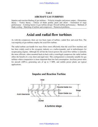
  • 1. www.Vidyarthiplus.com Unit-1 AIRCRAFT GAS TURBINES Impulse and reaction blading of gas turbines – Velocity triangles and power output – Elementary theory – Vortex theory – Choice of blade profile, pitch and chord – Estimation of stage performance – Limiting factors in gas turbine design- Overall turbine performance – Methods of blade cooling – Matching of turbine and compressor – Numerical problems. Axial and radial flow turbines As with the compressor, there are two basic types of turbine—radial flow and axial flow. The vast majority of gas turbines employ the axial flow turbine. The radial turbine can handle low mass flows more efficiently than the axial flow machine and has been widely used in the cryogenic industry as a turbo-expander, and in turbochargers for reciprocating engines. Although for all but the lowest powers the axial flow turbine is normally the more efficient, when mounted back-to-back with a centrifugal compressor the radial turbine offers the benefit of a very short and rigid rotor. This configuration is eminently suitable for gas turbines where compactness is more important than low fuel consumption. Auxiliary power units for aircraft (APUs), generating sets of up to 3 MW, and mobile power plants are typical applications. Impulse and Reaction Turbine www.Vidyarthiplus.com
  • 2. www.Vidyarthiplus.com Work can be extracted from a gas at a higher inlet pressure to the lower back pressure by allowing it to flow through a turbine. In a turbine as the gas passes through, it expands. The work done by the gas is equivalent to the change of its enthalpy. It is a well known fact that the turbines operate on the momentum principle. Part of the energy of the gas during expansion is converted into kinetic energy in the flow nozzles. The gas leaves these stationary nozzles at a relatively higher velocity. Then it is made to impinge on the blades over the turbine rotor or wheel. Momentum imparted to the blades turns the wheel. Thus, the two primary parts of the turbine are, (i) The stator nozzles, and (ii) the turbine rotor blades. Normally a turbine stage is classified as (i) an impulsion stage, and (ii) a reaction stage An impulse stage is characterized by the expansion of the gas which occurs only in the stator nozzles. The rotor blades act as directional vanes to deflect the direction of the flow. Further, they convert the kinetic energy of the gas into work by changing the momentum of the gas more or less at constant pressure. A reaction stage is one in which expansion of the gas takes place both in the stator and in the rotor. The function of the stator is the same as that in the impulse stage, but the function in the rotor is two fold. (i) the rotor converts the kinetic energy of the gas into work, and (ii) contributes a reaction force on the rotor blades. The reaction force is due to the increase in the velocity of the gas relative to the blades. This results from the expansion of the gas during its passage through the rotor. A Single Impulse Stage Impulse machines are those in which there is no change of static or pressure head of the fluid in the rotor. The rotor blades cause only energy transfer and there is no energy transformation. The energy transformation from pressure or static head to kinetic energy or vice versa takes place in fixed blades only. As can be seen from the below figure that in the rotor blade passage of an impulse turbine there is no acceleration of the fluid, i.e., there is no energy transformation. www.Vidyarthiplus.com
  • 3. www.Vidyarthiplus.com Hence, the chances are greater for separation due to boundary layer growth on the blade surface. Due to this, the rotor blade passages of the impulse machine suffer greater losses giving lower stage efficiencies. The paddle wheel, Pelton wheel and Curtis stem turbine are some examples of impulse machines. www.Vidyarthiplus.com
  • 4. www.Vidyarthiplus.com A Single Reaction Stage The reaction stages are those, in which, changes in static or pressure head occur both in the rotor and stator blade passages. Here, the energy transformation occurs both in fixed as well as moving blades. The rotor experiences both energy transfer as well as energy transformation. Therefore, reaction turbines are considered to be more efficient. This is mainly due to continuous acceleration of flow with lower losses. The degree of reaction of a turbomachine stage may be defined as the ratio of the static or pressure head change occurring in the rotor to the total change across the stage. Note: Axial-flow turbine with 50% reaction have symmetrical blades in their rotor and stators. It may be noted that the velocity triangles at the entry and exit of a 50% reaction stage are also symmetrical. www.Vidyarthiplus.com
  • 5. www.Vidyarthiplus.com Velocity Triangles of a Single Stage Machine The flow geometry at the entry and exit of a turbomachine stage is described by the velocity triangles at these stations. The velocity triangles for a turbomachine contain the following three components. 1. The peripheral / whirl / tangential velocity (u) of a rotor blades 2. The absolute velocity (c ) of the fluid and 3. The relative velocity (w or v) of the fluid These velocities are related by the following well-known vector equation. This simple relation is frequently used and is very useful in drawing the velocity triangles for turbomachines. www.Vidyarthiplus.com
  • 6. www.Vidyarthiplus.com The notation used here to draw velocity triangles correspond to the x-y coordinates; the suffix (a or α) identifies components in the axial direction and suffix (t) refers to tangential direction. Air angles in the absolute system are denoted by alpha (α), where as those in the relative system are represented by beta (β). Since the stage is axial, the change in the mean diameter between its entry and exit can be neglected. Therefore, the peripheral or tangential velocity (u) remains constant in the velocity triangles. It can be proved from the geometry that ct2 + ct3 = wt2 + wt3 It is often assumed that the axial velocity component remains constant through the stage. For such condition, ca = ca1 = ca2 = ca3 www.Vidyarthiplus.com
  • 7. www.Vidyarthiplus.com For constant axial velocity yields a useful relation, tan α2 + tan α3 = tan β2 + tan β3 Expression for Work Output Though force and torque are exerted on both stationary and moving blades alike, work can only be done on the moving rotor blades. Thus the rotor blades transfer energy from the fluid to the shaft. The stage work in an axial turbine (u3 = u2 = u) can be written as, W = u2 ct2 – u3ct3 = u{ct2- (-ct3)} = u(ct2-ct3) {Note: Usually this equation will be written with a minus sign between ct2 and ct3. Whenever this is written with a plus sign it is implied that ct3 is negative} This equation can also be expressed in another form,  ct 2 ct 3  W = u  +  u   u 2 c  The first term  t 2  in the bracket depends on the nozzle or fixed angle (α2) and the ratio  u  u c  . The contribution of the second term  t 3  to the work is generally small. It is also c2  u  observed that the kinetic energy of the fluid leaving the stage is greater for larger values of ct3. The leaving loss from the stage is minimum when ct3 = 0, i.e., when the discharge from the stage is axial (c3 = ca3). However, this condition gives lesser stage work as can be seen from the above two equations. σ = www.Vidyarthiplus.com
  • 8. www.Vidyarthiplus.com Blade loading and Flow coefficients Performance of turbomachines are characterized by various dimensionless parameters. For example, loading coefficient (ψ) and the flow coefficient (Ф) have been defined as, W Ψ= 2 u c φ = a u Since the work, W in the above equation is frequently referred to as the blade or stage work, the coefficient, ψ would also be known as the blade or stage loading coefficient. For constant axial velocity (ca), it can be shown that Ψ = Ф(tan α2 + tan α3) = Ф(tan β2 + tan β3) The Ф – ψ plots are useful in comparing the performances of various stages of different sizes and geometries. Blade and Stage efficiencies Even though the blade and stage work (outputs) are the same, the blade and the stage efficiencies need not be equal. This is because the energy inputs to the rotor blades and the stage (fixed blade ring plus the rotor) are different. The blade efficiency is also known as the utilization factor (ε) which is an index of the energy utilizing capability of the rotor blades. Thus, ε = ηb = Rotor blade work / Energy supplied to the rotor blades = W / Erb W = u2 ct2 + u3 ct3 = 1 2 2 1 2 1 3 2 2 c 2 − c3 + u 2 − u 3 + w3 − w2 2 2 2 ( ) ( ) ( ) The energy supplied to the rotor blades is the absolute kinetic energy in the jet at the entry plus the kinetic energy change within the rotor blades. www.Vidyarthiplus.com
  • 9. www.Vidyarthiplus.com Erb = 1 2 1 2 1 3 2 2 c2 + w3 − w2 + u2 − u3 2 2 2 ( ) ( ) For axial machines, u = u2 = u3 ε = ηb = (c 2 2 ) ( ( 2 2 2 − c3 + w3 − w2 2 2 2 c 2 + w3 − w2 ) ) Maximum utilization factor for a single impulse stage. u (ct 2 + ct 3 ) ε= 1 2 c2 2 After rearranging the terms, we have η b = ε = 4 (σ sin α 2 − σ 2 ) This shows that the utilization factor is a function of the blade-to-gas speed ratio and the nozzle angle. www.Vidyarthiplus.com
  • 10. www.Vidyarthiplus.com Elementary theory of axial flow turbine Fig.7.2 Typical representations of velocity triangles www.Vidyarthiplus.com
  • 11. www.Vidyarthiplus.com The above Figures show the velocity triangles for one axial flow turbine stage and the nomenclature employed. The gas enters the row of nozzle blades (These are also known as 'stator blades' and 'nozzle guide vanes') with a static pressure and temperature, P1, T1 and a velocity C1 is expanded to P2,T2 and leaves with an increased velocity C2 at an angle α2. The rotor blade inlet angle will be chosen to suit the direction β2 of the gas velocity V2 relative to the blade at inlet. β2and V2 are found by vectorial subtraction of the blade speed U from the absolute velocity C2. After being deflected, and usually further expanded, in the rotor blade passages, the gas leaves at P3, T3 with relative velocity V3 at angle β3. Vectorial addition of U yields the magnitude and direction of the gas velocity at exit from the stage, C3 and α3. α3 is known as the swirl angle. dimensional effects. www.Vidyarthiplus.com
  • 12. www.Vidyarthiplus.com Vortex theory It was pointed out earlier that the shape of the velocity triangles must vary from root to tip of the blade because the blade speed U increases with radius. Another reason is that the whirl component in the flow at outlet from the nozzles causes the static pressure and temperature to vary across the annulus. With a uniform pressure at inlet, or at least with a much smaller variation because the whirl component is smaller, it is clear that the pressure drop across the nozzle will vary giving rise to a corresponding variation in efflux velocity C2. Twisted blading designed to take account of the changing gas angles is called vortex blading. It has been common steam turbine practice, except in low-pressure blading where the blades are very long, to design on conditions at the mean diameter, keep the blade angles constant from root to tip, and assume that no additional loss is incurred by the variation in incidence along the blade caused by the changing gas angles. Comparative tests have been conducted by the earlier researchers on a single-stage gas turbine of radius ratio 1-37, using in turn blades of constant angle and vortex blading. The results showed that any improvement in efficiency obtained with vortex blading was within the margin of experimental error. This contrasts with similar tests on a 6-stage axial compressor, by another researcher, which showed a distinct improvement from the use of vortex blading. This was, however, not so much an improvement in efficiency (of about 1-5 per cent) as in the delay of the onset of surging which of course does not arise in accelerating flow. It appears, therefore, that steam turbine designers have been correct in not applying vortex theory except when absolutely necessary at the LP end. They have to consider the additional cost of twisted blades for the very large number of rows of blading required, and they know that the Rankine cycle is relatively insensitive to component losses. Conversely, it is not surprising that the gas turbine designer, struggling to achieve the highest possible component efficiency, has consistently used some form of vortex blading which it is felt intuitively must give a better performance however small. Vortex theory has been outlined earlier by Cohen and others where it was shown that if the elements of fluid are to be in radial equilibrium, an increase in static pressure from root to tip is necessary whenever there is a whirl component of velocity. Figure 7.8 shows (see below) why the gas turbine designer cannot talk of impulse or 50 per cent reaction stages. The proportion of the stage pressure or temperature drop which occurs in the rotor must increase from root to tip. Although Fig. 7.8 refers to a single-stage turbine with axial inlet velocity and no swirl at outlet, the whirl component at inlet and outlet of a repeating stage will be small compared with CW2- the reaction will therefore still increase from root to tip, if somewhat less markedly. www.Vidyarthiplus.com
  • 13. www.Vidyarthiplus.com Choice of blade profile, pitch and chord The next step is to choose stator and rotor blade shapes which will accept the gas incident upon the leading edge, and deflect the gas through the required angle with the minimum loss. An overall blade loss coefficient Y (or A) must account for the following sources of friction loss. (a) Profile loss—associated with boundary layer growth over the blade profile (including separation loss under adverse conditions of extreme angles of incidence or high inlet Mach number). (b) Annulus loss—associated with boundary layer growth on the inner and outer walls of the annulus. (c) Secondary flow loss—arising from secondary flows which are always present when a wall boundary layer is turned through an angle by an adjacent curved surface. (d) Tip clearance loss—near the rotor blade tip the gas does not follow the intended path, fails to contribute its quota of work output, and interacts with the outer wall boundary layer. The profile loss coefficient Yp is measured directly in cascade tests similar to those described for compressor blading. Losses (b) and (c) cannot easily be separated, and they are accounted for by a secondary loss coefficient Ys. www.Vidyarthiplus.com
  • 14. www.Vidyarthiplus.com The tip clearance loss coefficient, which normally arises only for rotor blades, will be denoted by Yk. Thus the total loss coefficient Y comprises the accurately measured two-dimensional loss Yp, plus the three-dimensional loss (Ys+Yk) which must be deduced from turbine stage test results. All that is necessary for our present purpose for finding the choice of blade profile is limited to the knowledge of the sources of loss. Figure 7.11 shows a conventional steam turbine blade profile constructed from circular arcs and straight lines. Gas turbines have until recently used profiles closely resembling this, although specified by aerofoil terminology. www.Vidyarthiplus.com
  • 15. www.Vidyarthiplus.com Note that the blade profile will be completely determined when (a) the pitch/width ratio (s/w) is established, and (b) both the camber line angle α' and blade thickness/pitch ratio have been calculated for various values of x between 0 and 1. www.Vidyarthiplus.com
  • 16. www.Vidyarthiplus.com Turbine Performance The performance of turbine is limited principally by two factors: compressibility and stress. Compressibility limits the mass flow that can pass through a given turbine and, stress limits the wheel speed U. The work per stage depends on the square of the wheel speed. However, the performance of the engine depends very strongly on the maximum temperature. Of course, as the maximum temperature increases, the allowable stress level diminishes; hence in the design of the engine there must be a compromise between maximum temperature and maximum rotor tip speed U. For given pressure ratio and adiabatic efficiency, the turbine work per unit mass is proportional to the inlet stagnation temperature. Since, in addition, the turbine work in a jet or turboshaft engine is commonly two or three times the useful energy output of the engine, a 1% increase in turbine inlet temperature can produce a 2% or 3% increase in engine output. This considerable advantage has supplied the incentive for the adoption of fairly elaborate methods for cooling the turbine nozzle and rotor blades. Estimation of stage performance The last step in the process of arriving at the preliminary design of a turbine stage is to check that the design is likely to result in values of nozzle loss coefficient and stage efficiency which were assumed at the outset. If not, the design calculations may be repeated with more probable values of loss coefficient and efficiency. When satisfactory agreement has been reached, the final design may be laid out on the drawing board and accurate stressing calculations can be performed. Before proceeding to describe a method of estimating the design point performance of a stage, however, the main factors limiting the choice of design, which we have noted during the course of the worked example, will be summarized. The reason we considered a turbine for a turbojet engine was simply that we would thereby be working near those limits to keep size and weight to a minimum. The designer of an industrial gas turbine has a somewhat easier task: he will be using lower temperatures and stresses to obtain a longer working life, and this means lower mean blade speeds, more stages, and much less stringentaerodynamic limitations. A power turbine, not mechanically coupled to the gas generator, is another case where much less difficulty will be encountered in arriving at a satisfactory solution. The choice of gear ratio between the power turbine and driven component is normally at the disposal of the turbine designer, and thus the rotational speed can be varied to suit the turbine, instead of the compressor as we have assumed here. www.Vidyarthiplus.com
  • 18. www.Vidyarthiplus.com The cooled turbine Figure 7.29 illustrates the methods of blade cooling that have received serious attention and research effort. Apart from the use of spray cooling for thrust boosting in turbojet engines, the liquid systems have not proved to be practicable. There are difficulties associated with www.Vidyarthiplus.com
  • 19. www.Vidyarthiplus.com channelling the liquid to and from the blades—whether as primary coolant for forced convection or free convection open thermosyphon systems, or as secondary coolant for closed thermosyphon systems. It is impossible to eliminate corrosion or the formation of deposits in open systems, and very difficult to provide adequate secondary surface cooling area at the base of the blades for closed systems. The only method used successfully in production engines has been internal, forced convection, air cooling. With 1-5-2 per cent of the air mass flow used for cooling per blade row, the blade temperature can be reduced by between 200 and 300 °C. Using current alloys, this permits turbine inlet temperatures of more than 1650 К to be used. The blades are either cast, using cores to form the cooling passages, or forged with holes of any desired shape produced by electrochemical or laser drilling. Figure 7.30 shows the type of turbine rotor blade introduced in the 1980s. The next step forward is likely to be achieved by transpiration cooling, where the cooling air is forced through a porous blade wall. This method is by far the most economical in cooling air, because not only does it remove heat from the wall more uniformly, but the effusing layer of air insulates the outer surface from the hot gas stream and so reduces the rate of heat transfer to the blade. Successful application awaits further development of suitable porous materials and techniques of blade manufacture. We are here speaking mainly of rotor blade cooling because this presents the most difficult problem. Nevertheless it should not be forgotten that, with high gas temperatures, oxidation becomes as significant a limiting factor as creep, and it is therefore equally important to cool even relatively unstressed components such as nozzle blades and annulus walls. www.Vidyarthiplus.com
  • 20. www.Vidyarthiplus.com Figure 7.31 (a) illustrates the principal features of nozzle blade cooling. The air is introduced in such a way as to provide jet impingement cooling of the inside surface of the very hot leading edge. The spent air leaves through slots or holes in the blade surface (to provide some film cooling) or in the trailing edge. FIG. 7.31 (a) Turbine nozzle cooling [(b) courtesy Rolls-Royce] www.Vidyarthiplus.com
  • 22. www.Vidyarthiplus.com Figure 7.35: Shows a typical temperature distribution at the mid-span of a blade designed to operate with Tg= 1500 К and Tсг = 320 К. It may be noted that the final design calculation for a cooled blade will involve an estimation of the two-dimensional temperature distribution over the blade cross-section at several values of l/L. Finite difference methods are used to solve the differential equations, and conduction within the blade is taken into account. Figure 7.35 shows a typical temperature distribution at the midspan of a blade designed to operate with Tg= 1500 К and Гсг = 320 К. It emphasizes one of the main problems of blade cooling, i.e. that of obtaining adequate cooling at the trailing edge. Finally, an estimation will be made of the thermal stresses incurred with due allowance for redistribution of stress by creep: with cooled blades the thermal stresses can dominate the gas bending stresses and be comparable with the centrifugal tensile stresses. Finally, mention must be made of an alternative approach to the high- temperature turbine—the use of ceramic materials which obviates the need for elaborate cooling passages. Much effort has been expended on the development of silicon nitride and silicon carbide materials for small turbine rotors (both axial and radial) in which it would be difficult to incorporate cooling passages. Adequate reliability and life are difficult to achieve, but demonstrator engines have been ran for short periods. Ceramic rotor blades are being investigated for use in stationary gas turbines for powers up to about 5 MW, and experimental trials are expected in the late 1990s. The use of ceramic turbines in production engines, however, remains an elusive goal three decades after optimistic forecasts about their introduction. Blade Cooling Blade cooling is the most effective way of maintaining high operating temperatures making use of the available material. Blade cooling may be classified based on the cooling site as external cooling and internal cooling. Another classification based on the cooling medium is liquid cooling and air cooling. www.Vidyarthiplus.com
  • 23. www.Vidyarthiplus.com External Cooling The external surface of the gas turbine blade is cooled by making use of compressed air from the compressor. Other methods of external cooling are film cooling and transpiration cooling. Internal Cooling Internal cooling of blades is achieved by passing air or liquid through internal cooling passages from hub towards the blade tip. The cooling of the blades is achieved by conduction and convection. Hollow blades can also be manufactured with a core and internal cooling passage. Based on the cooling medium employed, blade cooling may be classified into liquid cooling and air cooling. Requirements for Efficient Blade Cooling In a conventional cooled blade, cooling is obtained due to convection by passing cooling air through internal passages within the blade. The success in obtaining the large reduction in metal temperature at the expense of a small quantity of cooling flow is governed by the skill in devising and machining the cooling passages. Because the internal cooling relies on the cooling air scrubbing against the cooling surface, the internal surface area must be large and the velocity of the cooling air must be high. This implies that the cross-sectional flow area of the passage must be small. The design of the blade internal geometry for cooling is more complex because of the various aerodynamic, heat transfer, stress and mechanical design criteria that must be satisfied. The most successful designs have incorporated radial passages through which cooling air passes, escaping at the tip. The radial flow turbine In a radial flow turbine, gas flow with a high tangential velocity is directed inwards and leaves the rotor with as small a whirl velocity as practicable near the axis of rotation. The result is that the turbine looks very similar to the centrifugal compressor, but with a ring of nozzle vanes replacing the diffuser vanes as in Fig. 7.37. Also, as shown there would normally be a diffuser at the outlet to reduce the exhaust velocity to a negligible value. www.Vidyarthiplus.com
  • 27. www.Vidyarthiplus.com Turbine and Compressor Matching The problem of matching turbine and compressor performance has great importance for jet engines, which must operate under conditions involving large variations in thrust, inlet pressure, and temperature, and flight Mach number. Matching the components of turbofan and turboprop engines involves similar considerations and procedures. Essentially the matching problem is simple, though the computation can be length. The steady-state engine performance at each speed is determined by two conditions: continuity of flow and a power balance. The turbine mass flow must be the sum of the compressor mass flow and the fuel flow, minus compressor bleed flow. Also the power output of the turbine must be equal to that demanded by the compressor. In principle, the matching computations could proceed as follows: 1. Select operating speed 2. Assume turbine inlet temperature 3. Assume compressor pressure ratio 4. Calculate compressor work per unit mass 5. Calculate turbine pressure ratio required to produce this work 6. Check to see if compressor mass flow plus fuel flow equals turbine mass flow; if not, assume a new value of compressor pressure ratio and repeat steps 4, 5, and 6 until continuity is satisfied. 7. Now calculate the pressure ratio across the jet nozzle from the pressure ratios across the diffuser, compressor, combustor, and turbine. 8. Calculate the area of jet nozzle outlet necessary to pass the turbine mass flow calculated in step 6 with pressure ratio calculated in step 7 and the stagnation temperature calculated. If the calculated area does not equal the actual exit area, assume a new value of turbine inlet temperature (step-2) and repeat the entire procedure. www.Vidyarthiplus.com
  • 28. www.Vidyarthiplus.com The designer will try to match turbine and compressor so that the compressor is operating near its peak efficiency through the entire range of operation, as shown in the below figure, where the operating line (i.e., the locus of stead-state matching condition) runs through the centers of the islands defined by the constant-efficiency lines. www.Vidyarthiplus.com
  • 29. www.Vidyarthiplus.com The essence of compressor-turbine matching is to find a speed at which the turbine will run delivering power to the compressor and permit excess power in the form of adequate jet pressure for expansion through the nozzle or additional turbine stages from which power can be derived to run a propeller or helicopter rotor as the case may be. www.Vidyarthiplus.com
  • 30. www.Vidyarthiplus.com Problems In a single-stage impulse turbine the nozzle discharges the fluid on to the blades at an angle of 650 to the axial direction and the fluid leaves the blades with an absolute velocity of 300 m/s at an angle of 300 to the axial direction. If the blades have equal inlet and outlet angles and there is no axial thrust, estimate the blade angle, power produced per kg/s of the fluid and blade efficiency. Solution: Since the axial thrust is zero, Ca3 = Ca2 = Ca w3 = w2 www.Vidyarthiplus.com
  • 31. www.Vidyarthiplus.com ca3 = ca2 = ca = ca3 x cos α3 = 300 x cos 30 = 259.8 m/s c2 = ca2/cos α2 = 259.8/cos 65 = 614.7 m/s u = ct2 – wt2 = wt3 - ct3 c2 sin α2 - ca2 tan β2 = ca3 tan β3 – c3 sin α3 Since ca2 = ca3 = ca and β2 = β3 = β 2ca tan β = c2 sin α2 + c3 sin α3 tan β = (614.7 x sin 65 + 300 x sin 30) / 2 x 259.8 = 1.3609 β = 53.7 0 β2 = β3 = 53.7 0 u = c2 sin α2 - ca2 tan β2 = 614.7 x sin 65 – 259.8 x tan 53.7 = 203.43 m/s ct2 = c2 sin α2 = 614.7 x sin 65 = 557.1 m/s ct3 = c3 sin α3 www.Vidyarthiplus.com
  • 32. www.Vidyarthiplus.com = 300 x sin 30 = 150 m/s WT = 203.43 x (557.1 + 150) x 10-3 = 144 kJ/kg σ = u/c2 = 203.43 / 614.7 = 0.33 Blade efficiency = 4 (σ sin α2 - σ2) = 4 x (0.33 x sin 65 – 0.332) = 0.761 = 76.1 % www.Vidyarthiplus.com
  • 33. www.Vidyarthiplus.com Aircraft Engine Performance Parameters Uninstalled thrust of a jet engine (single inlet and single exhaust) is given by Uninstalled thrust of a jet engine (single inlet and single exhaust) is given by It is most desirable to expand the exhaust gas to the ambient pressure, which gives www.Vidyarthiplus.com
  • 34. www.Vidyarthiplus.com In this case, the uninstalled thrust equation becomes, The installed thrust T is equal to the uninstalled thrust F minus the inlet drag Dinlet and minus nozzle drag Dnozzle , or T = F – Dinlet - Dnozzle Problem: An advanced fighter engine operating at Mach 0.8 and 10 km altitude has the following unistalled performance data and uses a fuel with low heating value 42,800 kJ/kg: Uninstalled thrust = 50 kN Mass flow rate of air = 45 kg/sec Mass flow rate of fuel = 2.65 kg/sec Determine the specific thrust, thrust specific fuel consumption, exit velocity, thermal efficiency, propulsive efficiency, and overall efficiency (assume exit pressure equal to ambient pressure). Find the installed thrust when the total drag is equal to 10% of the uninstalled thrust. Solution: www.Vidyarthiplus.com
  • 35. www.Vidyarthiplus.com Fs = 50/45 = 1.1111kN/(kg/sec) = 1111.1 m/s TSFC = 2.65 / 50 = 0.053 (kg/sec)/kN = 53 mg/N-sec V0 = Mo ao = 239. 6 m/sec Using the above equation exit velocity, Ve is obtained as 1275.6 m/s www.Vidyarthiplus.com
  • 36. www.Vidyarthiplus.com Power output of the engine = 37.475 x 10⁶ W Power input to the engine through fuel = 113.42 x 10⁶ W Propulsive power or Thrust Power = 50,000 x 239.6 Thermal efficiency = 37.475 x 10⁶ / 113.42 x 106 = 33.04 % Propulsive Efficiency = 50,000 x 239.6 / 37,475 x 106 = 31.97 % Overall efficiency = 50,000 x 239.6 / 113.42 x 106 = 10.56 % For additional numerical problems please refer the following books 1. Mathur, M., and Sharma, R.P., “Gas Turbines and Jet and Rocket Propulsion”, Standard Publishers, New Delhi, 1988. 2. Ganesan, V., Gas Turbines, Tata McGraw-Hill Publishing Company Limited, New Delhi. Second Edn. 2003. Additional reading 1. Hill, P.G. & Peterson, C.R. “Mechanics & Thermodynamics of Propulsion” Addison – Wesley Longman INC, 1999. 2. Cohen, H., Rogers, G.F.C. and Saravanamuttoo, H.I.H., “Gas Turbine Theory”, Longman Co., ELBS Ed., 1989. www.Vidyarthiplus.com
  • 37. www.Vidyarthiplus.com Unit-2 RAMJET PROPULSION Operating principle – Sub critical, critical and supercritical operation – Combustion in ramjet engine – Ramjet performance – Sample ramjet design calculations – Introduction to scramjet – Preliminary concepts in supersonic combustion – Integral ram- rocket- Numerical problems. Ramjets Introduction • • • • • Ramjets can be thought of as propulsive devices evolved out of turbojets. Ramjets operates well only at high speeds, typically between M = 2.0 and 4.0. The combustion mode being not very different from that of an afterburner, the specific fuel consumption is comparable to that of afterburner. The ramjet, unlike turbojet and turbofan does not produce any thrust at zero speed. Ramjets are mostly contemplated for use in military applications. www.Vidyarthiplus.com
  • 38. www.Vidyarthiplus.com SCRAM JET ENGINES • • • • • • • A scram jet engine is an engine that is much lighter than a conventional jet engine, can propel an object at speeds of over 5000 miles per hour and has no moving parts. If you could get it to work, the trip from London to Sydney would only take two hours! This technology would also be very useful to launch small satellites. The engine runs on oxygen, which it gets from the atmosphere, and a small amount of hydrogen. The engine would save a fantastic amount on the cost of fuel. This technology has been around since the 1950s but the problem is the motor will only become efficient at five times the speed of sound or Mach 5. Because of this the plane would need two engines, an engine capable of getting it to Mach 5 and a Scram Jet. A ramjet engine A scramjet engine www.Vidyarthiplus.com
  • 39. www.Vidyarthiplus.com • • • • • • • • • • • • • • • • • • • A ramjet has no moving parts and achieves compression of intake air by the forward speed of the air vehicle. Air entering the intake of a supersonic aircraft is slowed by aerodynamic diffusion created by the inlet and diffuser to velocities comparable to those in a turbojet augmenter. The expansion of hot gases after fuel injection and combustion accelerates the exhaust air to a velocity higher than that at the inlet and creates positive push. Scramjet is an acronym for Supersonic Combustion Ramjet. The scramjet differs from the ramjet is that combustion takes place at supersonic air velocities through the engine. It is mechanically simple, but vastly more complex aerodynamically than a jet engine. Hydrogen is normally the fuel used. A scramjet (supersonic combustion ramjet) is a variation of a ramjet with the key difference being that the flow in the combustor is supersonic. At higher speeds it is necessary to combust supersonically to maximize the efficiency of the combustion process. Projections for the top speed of a scramjet engine (without additional oxidizer input) vary between Mach 12 and Mach 24 (orbital velocity), but the X-30 research gave Mach 17 due to combustion rate issues. By way of contrast, the fastest conventional air-breathing, manned vehicles, such as the U.S. Air Force SR-71, achieve slightly more than Mach 3.2 and rockets achieved Mach 30+ during Apollo. Like a ramjet, a scramjet essentially consists of a constricted tube through which inlet air is compressed by the high speed of the vehicle, fuel is combusted, and then the exhaust jet leaves at higher speed than the inlet air. Also like a ramjet, there are few or no moving parts. In particular there is no high speed turbine as in a turbofan or turbojet engine that can be a major point of failure. A scramjet requires supersonic airflow through the engine, thus, similar to a ramjet, scramjets have a minimum functional speed. This speed is uncertain due to the low number of working scramjets, relative youth of the field, and the largely classified nature of research using complete scramjet engines. However it is likely to be at least Mach 5 for a pure scramjet, with higher Mach numbers 7-9 more likely. Thus scramjets require acceleration to hypersonic speed via other means. A hybrid ramjet/scramjet would have a lower minimum functional Mach number, and some sources indicate the NASA X-43A research vehicle is a hybrid design. Recent tests of prototypes have used a booster rocket to obtain the necessary velocity. Air breathing engines should have significantly better specific impulse while within the atmosphere than rocket engines. However scramjets have weight and complexity issues that must be considered. While very short suborbital scramjets test flights have been successfully performed, perhaps www.Vidyarthiplus.com
  • 40. www.Vidyarthiplus.com • • • • • • • • • • • significantly no flown scramjet has ever been successfully designed to survive a flight test. The viability of scramjet vehicles is hotly contested in aerospace and space vehicle circles, in part because many of the parameters which would eventually define the efficiency of such a vehicle remain uncertain. This has led to grandiose claims from both sides, which have been intensified by the large amount of funding involved in any hypersonic testing. Some notable aerospace gurus such as Henry Spencer and Jim Oberg have gone so far as calling orbital scramjets 'the hardest way to reach orbit', or even 'scramjets' due to the extreme technical challenges involved. Major, well funded projects, like the X-30 were cancelled before producing any working hardware. The scramjet is a proposed solution to both of these problems, by modifications of the ramjet design. The main change is that the blockage inside the engine is reduced, so that the air isn't slowed down as much. This means that the air is cooler, so that the fuel can burn properly. Unfortunately the higher speed of the air means that the fuel has to mix and burn in a very short time, which is difficult to achieve. To keep the combustion of the fuel going at the same rate, the pressure and temperature in the engine need to be kept constant. Unfortunately, the blockages which were removed from the ramjet were useful to control the air in the engine, and so the scramjet is forced to fly at a particular speed for each altitude. This is called a "constant dynamic pressure path" because the wind that the scramjet feels in its face is constant, making the scramjet fly faster at higher altitude and slower at lower altitude. The inside of a very simple scramjet would look like two kitchen funnels attached by their small ends. The first funnel is the intake, and the air is pushed through, becoming compressed and hot. In the small section, where the two funnels join, fuel is added, and the combustion makes the gas become even hotter and more compressed. Finally, the second funnel is a nozzle, like the nozzle of a rocket, and thrust is produced. Note that most artists' impressions of scramjet-powered vehicle designs depict waveriders where the underside of the vehicle forms the intake and nozzle of the engine. This means that the intake and nozzle of the engine are asymmetric and contribute directly to the lift of the aircraft. A waverider is the required form for a hypersonic lifting body A scramjet is a type of engine which is designed to operate at the high speeds normally associated with rocket propulsion. It differs from a classic rocket by using air collected from the atmosphere to burn its fuel, as opposed to an oxidizer carried with the vehicle. Normal jet engines and ramjet engines also use air collected from the atmosphere in this way. The problem is that collecting air from the atmosphere causes drag, which increases quickly as the speed increases. www.Vidyarthiplus.com
  • 41. www.Vidyarthiplus.com • • • • • • • • • • • • • • • • Also, at high speed, the air collected becomes so hot that the fuel no longer burns properly. Theory All scramjet engines have fuel injectors, a combustion chamber, a thrust nozzle and an inlet, which compresses the incoming air. Sometimes engines also include a region which acts as a flame holder, although the high stagnation temperatures mean that an area of focused waves may be used, rather than a discrete engine part as seen in turbine engines. Other engines use pyrophoric fuel additives, such as silane, to avoid such issues. An isolator between the inlet and combustion chamber is often included to improve the homogeneity of the flow in the combustor and to extend the operating range of the engine. A scramjet is reminiscent of a ramjet. In a typical ramjet, the supersonic inflow of the engine is decelerated at the inlet to subsonic speeds and then reaccelerated through a nozzle to supersonic speeds to produce thrust. This deceleration, which is produced by a normal shock, creates a total pressure loss which limits the upper operating point of a ramjet engine. For a scramjet, the kinetic energy of the freestream air entering the scramjet engine is large compared to the energy released by the reaction of the oxygen content of the air with a fuel (say hydrogen). Thus the heat released from combustion at Mach 25 is around 10% of the total enthalpy of the working fluid. Depending on the fuel, the kinetic energy of the air and the potential combustion heat release will be equal at around Mach 8. Thus the design of a scramjet engine is as much about minimizing drag as maximizing thrust. This high speed makes the control of the flow within the combustion chamber more difficult. Since the flow is supersonic, no upstream influence propagates within the freestream of the combustion chamber. Thus throttling of the entrance to the thrust nozzle is not a usable control technique. In effect, a block of gas entering the combustion chamber must mix with fuel and have sufficient time for initiation and reaction, all the while travelling supersonically through the combustion chamber, before the burned gas is expanded through the thrust nozzle. This places stringent requirements on the pressure and temperature of the flow, and requires that the fuel injection and mixing be extremely efficient. Usable dynamic pressures lie in the range 20 to 200 kPa (0.2-2 bar), where • where q is the dynamic pressure of the gas www.Vidyarthiplus.com
  • 42. www.Vidyarthiplus.com • • • • • • • • • • • • • • • • ρ (rho) is the density of the gas v is the velocity of the gas Fuel injection and management is also potentially complex. One possibility would be that the fuel is pressurized to 100 bar by a turbo pump, heated by the fuselage, sent through the turbine and accelerated to higher speeds than the air by a nozzle. The air and fuel stream are crossed in a comb like structure, which generates a large interface. Turbulence due to the higher speed of the fuel lead to additional mixing. Complex fuels like kerosine need a long engine to complete combustion. The minimum Mach number at which a scramjet can operate is limited by the fact that the compressed flow must be hot enough to burn the fuel, and of high enough pressure that the reaction is finished before the air moves out the back of the engine. Additionally, in order to be called a scramjet, the compressed flow must still be supersonic after combustion. Here two limits must be observed: Firstly, since when a supersonic flow is compressed it slows down, the level of compression must be low enough (or the initial speed high enough) not to slow down the gas below Mach 1. If the gas within a scramjet goes below Mach 1 the engine will "choke", transitioning to subsonic flow in the combustion chamber. This effect is well known amongst experimenters on scramjets since the waves caused by choking are easily observable. Additionally, the sudden increase in pressure and temperature in the engine can lead to an acceleration of the combustion, leading to the combustion chamber exploding. Secondly, the heating of the gas by combustion causes the speed of sound in the gas to increase (and the Mach number to decrease) even though the gas is still traveling at the same speed. Forcing the speed of air flow in the combustion chamber under Mach 1 in this way is called "thermal choking". It is clear that a pure scramjet can operate at Mach numbers of 6-8, but in the lower limit, it depends on the definition of a scramjet. Certainly there are designs where a ramjet transforms into a scramjet over the Mach 3-6 range (Dual-mode scramjets). In this range however, the engine is still receiving significant thrust from subsonic combustion of "ramjet" type. The high cost of flight testing and the unavailability of ground facilities have hindered scramjet development. A large amount of the experimental work on scramjets has been undertaken in cryogenic facilities, direct-connect tests, or burners, each of which simulates one aspect of the engine operation. www.Vidyarthiplus.com
  • 43. www.Vidyarthiplus.com • • • • • • • • • • • Further, vitiated facilities, storage heated facilities, arc facilities and the various types of shock tunnels each have limitations which have prevented perfect simulation of scramjet operation. The HyShot flight test showed the relevance of the 1:1 simulation of conditions in the T4 and HEG shock tunnels, despite having cold models and a short test time. The NASA-CIAM tests provided similar verification for CIAM's C-16 V/K facility and the Hyper-X project is expected to provide similar verification for the Langley AHSTF , CHSTF and 8 ft HTT. Computational fluid dynamics has only recently reached a position to make reasonable computations in solving scramjet operation problems. Boundary layer modeling, turbulent mixing, two-phase flow, flow separation, and realgas aerothermodynamics continue to be problems on the cutting edge of CFD. Additionally, the modeling of kinetic-limited combustion with very fast-reacting species such as hydrogen makes severe demands on computing resources. Reaction schemes are numerically stiff, having typical times as low as 10-19 seconds, requiring reduced reaction schemes. Much of scramjet experimentation remains classified. Several groups including the US Navy with the SCRAM engine between 1968-1974, and the Hyper-X program with the X-43A have claimed successful demonstrations of scramjet technology. Since these results have not been published openly, they remain unverified and a final design method of scramjet engines still does not exist. The final application of a scramjet engine is likely to be in conjunction with engines which can operate outside the scramjet's operating range. Dual-mode scramjets combine subsonic combustion with supersonic combustion for operation at lower speeds, and rocket-based combined cycle (RBCC) engines supplement a traditional rocket's propulsion with a scramjet, allowing for additional oxidizer to be added to the scramjet flow. RBCCs offer a possibility to extend a scramjet's operating range to higher speeds or lower intake dynamic pressures than would otherwise be possible. • Advantages and disadvantages of scramjets Special cooling and materials • • Unlike a rocket that quickly passes mostly vertically through the atmosphere or a turbojet or ramjet that flies at much lower speeds, a hypersonic airbreathing vehicle optimally flies a "depressed trajectory", staying within the atmosphere at hypersonic speeds. Because scramjets have only mediocre thrust-to-weight ratios, acceleration would be limited. Therefore time in the atmosphere at hypersonic speed would be considerable, possibly 15-30 minutes. www.Vidyarthiplus.com
  • 44. www.Vidyarthiplus.com • • • • • Similar to a reentering space vehicle, heat insulation from atmospheric friction would be a formidable task. The time in the atmosphere would be greater than that for a typical space capsule, but less than that of the space shuttle. Therefore studies often plan on "active cooling", where coolant circulating throughout the vehicle skin prevents it from disintegrating from the fiery atmospheric friction. Active cooling could require more weight and complexity. There is also safety concern since it's an active system. Often, however, the coolant is the fuel itself, much in the same way that modern rockets use their own fuel and oxidizer as coolant for their engines. Both scramjets and conventional rockets are at risk in the event of a cooling failure. Half an engine • The typical waverider scramjet concept involves, effectively, only half an engine. The shockwave of the vehicle itself compresses the inlet gasses, forming the first half of the engine. Likewise, only fuel (the light component) needs tankage, pumps, etc. This greatly reduces craft mass and construction effort, but the resultant engine is still very much heavier than an equivalent rocket or conventional turbojet engine of similar thrust. Simplicity of design • Scramjets have few to no moving parts. Most of their body consists of continuous surfaces. With simple fuel pumps, reduced total components, and the reentry system being the craft itself, scramjet development tends to be more of a materials and modelling problem than anything else. Additional propulsion requirements • A scramjet cannot produce efficient thrust unless boosted to high speed, around Mach 5, depending on design, although, as mentioned earlier, it could act as a ramjet at low speeds. A horizontal take-off aircraft would need conventional turbofan or rocket engines to take off, sufficiently large to move a heavy craft. Also needed would be fuel for those engines, plus all engine associated mounting structure and control systems. Turbofan engines are heavy and cannot easily exceed about Mach 2-3, so another propulsion method would be needed to reach scramjet operating speed. That could be ramjets or rockets. Those would also need their own separate fuel supply, structure, and systems. Many proposals instead call for a first stage of droppable solid rocket boosters, which greatly simplifies the design. www.Vidyarthiplus.com
  • 45. www.Vidyarthiplus.com Pulsejet Pulsejet is a constant volume combustion device which is quite efficient only at low speeds and uses unsteady combustion for its operation. Once the system is started, it works by taking in air and fuel and combustion them during a part of the cycle and exhausting it during the next part of the cycle. In order to promote and sustain the operation, a flapper device of metal or plastic, in recent times, is used in front end. Supersonic Diffuser Super sonic diffuser may be divided into two separate parts: the supersonic inlet and the subsonic diffuser. Although this division is a convenient one, it must be remembered that the phenomena in the supersonic and subsonic parts of the diffuser can, and often do, interact. It should be remembered that the higher the Mach number, the greater will be our percentage loss in pressure across a normal shock. Thus, at very high mach numbers, there is an appreciable difference between (1) isentropic compression through out and (2) compression with a normal shock. The limitations imposed by the losses associated with a normal shock at higher Mach numbers stimulated the development of a modified simple inlet design which incorporates a spike or wedge in the nose section of the diffuser. The modified design utilizes the spike or wedge to produce an oblique shock at the nose section, and, the mach number after an oblique shock are greater than one. Consequently, in addition to the oblique shock, we have a normal shock near the minimum area section. The www.Vidyarthiplus.com
  • 46. www.Vidyarthiplus.com compression after the normal shock is of the standard subsonic diffuser type; that is, an increase in area decreases the velocity. It might be asked why a diffuser which has two shock waves, namely, an oblique and a normal shock, would give better results than a simple inlet which has only one normal shock. The reason for this is that the losses across a series of weak shock are less than the losses across one or several strong shocks. This means that the losses across the normal shock which follows the oblique shock are considerably less than the losses across a normal shock in the free stream. Increasing the number of oblique shocks before the normal shock reduces the losses through the shock system. It must be noted that the complexity of the inlet also increases as the number shocks increases. In addition to the number of shocks, the pressure losses are also function of the shock arrangement. It may be noted that the maximum total pressure recovery occurs when the total pressure recovery is the same across each of oblique shocks, and very nearly equal to that across the final normal shock. Mode of Supersonic Diffuser Operation The three basic modes operation frequently referred to are subcritical operation, critical operation, and supercritical operation. All these three inlets are operated at the design Mach number, MD, which by definition, means that the conical shock or conical shock extended will intersect the cowl lip. • • • • • At the subcritical operation, the normal shock is external and subsonic velocities exit at the cowl. For this condition mass-flow ratio based on capture area is less than one; spillage exists; the inlet is not swallowing air at maximum capacity; pressure recovery is low since some of the air goes through a single, near normal shock; inlet drag is high because of the intense shock; operation is generally unstable and conducive to a condition called “buzz” (normal shock moves in and out of the inlet at relatively high frequencies). An important instability that occurs during the subcritical operation of most supersonic inlets. This phenomenon, known as “buzz”, consists of a rapid oscillation of the inlet shock and flow pattern; the resultant internal disturbance is very detrimental to engine performance. In a ramjet, for instance, the onset of buzz usually extinguishes combustion. Although the pulses of the shock system are similar, the interval between pulses is not constant; hence buzz cannot be considered a periodic phenomenon. Although it is not thoroughly understood, buzz has been shown to be a function of conditions only at , and immediately downstream of, the inlet. In general subcritical operation is unsatisfactory and should be avoided. As the flow resistance downstream of the diffuser is increased, the mass-flow ratio can be reduced to its limit value of 0 at which point no flow exits. For critical operation, both maximum mass flow and ram recovery are attained for the design Mach number; thus condition represents the optimum performance condition. It has the disadvantage, however, of being, marginally unstable in actual applications www.Vidyarthiplus.com
  • 47. www.Vidyarthiplus.com because small changes in angles of attack or yaw or boundary layer separation can induce the critical mode of operation across the threshold into the subcritical regime. Consequently, for actual operation it is usually better to operate the inlet in a more stable condition, the supercritical regime. Typical modes of inlet operation The three basic modes operation frequently referred to aircraft inlets are subcritical operation, critical operation, and supercritical operation, which are shown schematically for a typical case in the above figure. With entirely diverging internal flow such as this, the normal shock position is determined by a downstream flow restriction rather than by the inlet geometry. Hence operating mode is sensitive to variations in exhaust-nozzle area and fuel flow rate. Subcritical operation entails “spilling” of flow and a normal shock upstream of the inlet. “Low” and “high” subcritical operations differ only in the extent of spilling. Supercritical operation occurs at the same mass flow as critical operation, but with increased losses, since the normal shock occurs at a higher Mach number. All these three inlets are operated at the design Mach number, MD, which by definition, means that the conical shock or conical shock extended will intersect the cowl lip. www.Vidyarthiplus.com
  • 50. www.Vidyarthiplus.com The ramjet has the virtue of maximum simplicity, with no need for turbomachinery, and maximum tolerance to high-temperature operation and minimum mass-per-unit thrust at suitable flight Mach numbers. The ramjet also has its limitations. As well as being generally incapable of steady operation at subsonic Mach numbers, it has an upper Mach number limit. For the conventional ramjet (in which the supersonic inlet air is slowed to subsonic speeds to provide stable combustion prior to the nozzle expansion), there is a limiting Mach number of about 6, above which the temperature of the air entering the combustor is so high that combustion cannot be completed. Most of the chemical energy of combustion is nonusefully transformed into dissociation reactions that on expansion do not provide the exhaust velocity needed for satisfactory ramjet performance. To avoid this problem, substantial research has been, and is still being, focused on the supersonic combustion ramjet (SCRAMJET). The difference between this and the conventional ramjet is that combustion is to take place in a supersonic stream. Fuel must be injected into the supersonic stream (without causing disruptive shock waves) and must mix and burn in a millisecond or so. Conventional fuels do not ignite quickly enough, and gaseous hydrogen seems the most likely candidate. Design of the fuel injector is a formidable challenge; so is the problem of cooling a vehicle designed to operate at Mach numbers of 4 or higher. Hydrogen could conceivably serve for structural cooling as well as for engine fuel. It will be clear from this discussion that future designs for supersonic (or even hypersonic) aircraft must cope with the design challenges of a whole range of flight Mach numbers. www.Vidyarthiplus.com
  • 51. www.Vidyarthiplus.com Supersonic Combustion The losses associated with subsonic ramjet combustion can be substantial. If ramjets are to be applied to hypersonic flight, additional problems arise because of extremely high temperature at the entrance to the combustion chamber. This not only makes vehicle cooling very difficult, but it leads to severe combustion loss due to dissociation. Figure shows the air temperature reached after adiabatic deceleration from a high-altitude ambient temperature of 220 K and from flight Mach number M to a chamber pressure of either 1 or 10 atm. For hypersonic flight (e.g. for M > 8) the temperature of the air in the chamber is quite dependent on the pressure: The higher the pressure, the less dissociation and the higher the temperature of the mixture. The temperature of the combustion products is likewise pressure dependent. Figure shows, for a combustion pressure of 10 atm and a flight Mach number of 10, there is no temperature rise due to combustion; all of the combustion energy is absorbed by dissociation. One sees from the above Figure, the strange result that, at sufficiently high Mach number, the temperature of the combustion products can be lower than that of the incoming air. Consideration of the speed with which the fuel and air can be converted into dissociation products may show that there is sufficient residence time in the combustion chamber to approach equilibrium composition. But during the subsequent expansion in the nozzle, one cannot take equilibrium composition for granted. It is quite possible that the expansion will be too rapid for the composition to readjust, after each step of temperature and pressure reduction, to a new equilibrium composition. If the expansion extremely rapid, the mixture may be effectively “frozen” with the initial (high-temperature) composition. This would mean that little of the combustion energy of the fuel (for the M = 10 case) would be available for acceleration of the combustion products to produce thrust. The chemical kinetics of the recombination processes in the nozzle would, in general, have a strong effect on the thrust and the propulsion efficiency of the engine. Some researchers have proposed the concept of the supersonic combustion as a way to avoid this dissociation loss as well as the stagnation pressure losses associated with deceleration in supersonic-to-subsonic inlets. With supersonic combustion, fluid temperatures are relatively low, and this decreases the dissociation loss because dissociation depends on static rather than stagnation temperature. Wall heat transfer, in contrast, depends essentially on stagnation temperature, so the wall-cooling problem is not removed by employing supersonic combustion. The stagnation pressure loss due to supersonic heating depends on the extent to which the fluid is being accelerated while combustion is taking place. The use of supersonic combustion requires fuel to be injected into, and mixed with, a supersonic stream without excessive shock losses. www.Vidyarthiplus.com
  • 53. www.Vidyarthiplus.com The main advantages of the ramjet engine are; 1. 2. 3. 4. 5. High temperature can be employed In the absence of rotating machinery its construction is very simple and cheap It can operate effectively at high supersonic Mach numbers It is not very sensitive to the quality of fuel It provides high thrust per unit weight and frontal area www.Vidyarthiplus.com
  • 54. www.Vidyarthiplus.com Ramjet engine’s Main disadvantages are; 1. 2. 3. 4. It requires a launching device at supersonic speed It is unsuitable for subsonic flight It has low thermal efficiency and high TSFC Its maximum operating altitude is limited Ideal Efficiency Various process occurring in the ramjet engine can be represented by an open circuit Brayton cycle. This cycle is considered here with the following assumptions: 1. Steady one-dimensional flow 2. Isentropic compression and expansion, ∆s = 0, ∆P0 = 0 3. Perfect gas 4. Constant pressure heat addition in the combustion chamber, P2 = P3 5. Very low Mach number in the combustion chamber. P2 ≈ P02 ≈ P03 T2 ≈ T02 ≈ T03 Compression and expansion process here are thermodynamically different from turbo jet engine. These process here experience only energy transformation; there is no energy transfer such as compressor and turbine work within the engine. Thrust work is obtained from the energy supplied in the fuel during process 2-3. Heat is rejected during process 41 outside the engine. However, the ideal efficiency of the ramjet engine is still given by Equation, 1 1 η i = 1 − = 1 − (γ −1) / γ t r Here, the temperature ratio, with the above assumption is given by t = T2 T T γ −1 2 = 02 = 01 = 1 + Mi T1 T1 T1 2 www.Vidyarthiplus.com
  • 55. www.Vidyarthiplus.com Substituting the value of t from the above Equation to the previous equation we get, γ −1 ηi = 1 − ηi = M 12 1 2 = γ −1 2 γ −1 2 1+ M1 1+ M1 2 2 1 = f (M 1 ) 2 1 1+ γ − 1 M 12 Though the actual thermal efficiency of the ramjet engine will be much lower than the value given by the above equation it demonstrates an important characteristic i.e., the efficiency increases with the flight Mach number and has a high value (76.19 % at M1 = 4) at higher operating Mach numbers. Other performance parameters and efficiencies defined for air-breathing engines are also applicable for the ram jet engine. www.Vidyarthiplus.com
  • 56. www.Vidyarthiplus.com The thermal efficiency or the Air standard Efficiency of the ideal cycle 1-2s-3-4s is given by, = work / heat supplied = 1 – Qr/Qs = 1 – (T4s – T1)/(T3-T2s) The pressure ratio in the compressor and turbine is same, i.e., r = P2/P1 = P3/P4 Therefore the corresponding temperature ratios are given by, ( γ −1) / γ t= P  T2 s T = 3 = r (γ −1) / γ =  2  P  T1 T4 s  1 η AS P  = 3  P   4 ( γ −1) / γ 1 1 = 1 − = 1 − (γ −1) / γ t r Numerical Problem Q. A ramjet engine operates at M = 1.5 at an altitude of 6500 m. The diameter of the inlet diffuser at entry is 50 cm and the stagnation temperature at the nozzle entry is 1600 K. The calorific value of the fuel used is 40 MJ/kg. The properties of the combustion gases are same as those of air (γ = 1.4, R = 287 J/kg K). The velocity of air at the diffuser exit is negligible. Calculate (a) the efficiency of the ideal cycle (b) flight speed (c) air flow rate (d) diffuser pressure ratio (e) fuel-air ratio (f) nozzle pressure ratio (g) nozzle jet Mach number (h) propulsive efficiency (i) and thrust. Assue the following values; ηD = 0.90, ηB = 0.98, ηj = 0.96, stagnation pressure loss in the combustion chamber = 0.02P02. www.Vidyarthiplus.com
  • 57. www.Vidyarthiplus.com At Z = 6500 m the properties of air are T1 = 245.90 K, p1 = 0.440 bar, a1 = 414.5 m/s Ρ = 0.624 kg/m3 (a) Ideal cycle efficiency ηi = 1 2 1 1+ γ − 1 M 12 = 0.310 Ans. (b) M1 = u/a1 U = M1 a1 = 1.5 x 314.5 = 471.75 m/s Flight speed = 1698.3 kmph Ans. ( C) Area of cross section of the diffuser inlet A1 = π d2/4 = π 0.52/4 = 0.1963 m2 www.Vidyarthiplus.com
  • 58. www.Vidyarthiplus.com m a = ρ1uA1 = 0.624 X 471.48 X 0.1963 Air flow rate = 57.752 kg/s Ans. (d) For negligible velocity at the diffuser exit, P02 = P2 ( γ −1) / γ  P2    −1 P  ηD =  1  γ −1 2 M1 2 ηD = 0.9, M1 = 1.5 P2/P1 = 3.2875 Ans. P2 = 3.2875 x 0.44 = 1.446 (e) T01 γ −1 2 = 1+ M 1 = 1.45 T1 2 = 1.45 x 245.9 = 356.55 K • • m a C p (T03 − T02 ) = η B m f Q f • f = mf • = C p (T03 − T02 ) / η B Q f ma f = 1.005 (1600-356.55)/0.98 x 40000 www.Vidyarthiplus.com
  • 59. www.Vidyarthiplus.com Fuel air ratio = 0.03188 Ans (f) P03 = P02 – 0.02 P02 = 0.98 P02 = 0.98 x 1.446 = 1.417 bar Nozzle pressure ratio, P03 1.417 = = 3.22 Ans P4 0.440 (g) The Mach number at the nozzle exit for a pressure ratio of 3.22 in an isentropic expansion would be M4s = 1.41; however, on account of irreversible expansion (ηj = 0.96) the exit velocity and Mach number will be slightly lower. T04 γ −1 2 =1+ M 4 s = 1 + 0.2 x 1.412 = 1.3976 T4 s 2 T4s = 1600/1.3976 = 1144.82 K T04 – T4 = ηj (T04-T4s) = 0.96 (1600-1144.82) = 1600 – 436.973 = 1163.027 K T04 = T4 + C24/2Cp C4 = 937.185 m/s a4 = (1.4 x 287 x 1163.027)0.5 = 683.596 m/s Nozzle jet Mach number, M4 = C4/a4 = 937.185/683.596 = 1.371 Ans (h) σ = u/c4 = 471.48/937.185 = 0.503 ηp = 2σ/(1+ σ) = 2 x 0.503 /(1+0.503) www.Vidyarthiplus.com
  • 60. www.Vidyarthiplus.com Propulsive efficiency = 0.6693 Ans (i) • m f = 57.752 x 0.03188 = 1.841 kg / s • • • m = ma + m f = 57.752 + 1.841 = 59.593 kg / s • • F = m C4 − m a u = (59.593 x 937.185 – 57.752 x 471.75) 10-3 Thrust = 28.614 kN Ans Ram rocket Air-augmented rockets (also known as rocket-ejector, ramrocket, ducted rocket, integral rocket/ramjets, or ejector ramjets) use the supersonic exhaust of some kind of rocket engine to further compress air collected by ram effect during flight to use as additional working mass, leading to greater effective thrust for any given amount of fuel than either the rocket or a ramjet alone. They represent a hybrid class of rocket/ramjet engines, similar to a ramjet, but able to give useful thrust from zero speed, and are also able in some cases to operate outside the atmosphere, with fuel efficiency not worse than both a comparable ramjet or rocket at every point. Operation A normal chemical rocket engine carries oxidizer and a fuel, sometimes pre-mixed, as in a solid rocket, which are then burned. The heat generated greatly increases the temperature of the mixture, which is then exhausted through a nozzle where it expands and cools. The exhaust is directed rearward through the nozzle, thereby producing a thrust forward. In this conventional design, the fuel/oxidizer mixture is both the working mass and energy source that accelerates it. One method of increasing the overall performance of the system is to collect either the fuel or the oxidizer during flight. Fuel is hard to come by in the atmosphere, but oxidizer in the form of gaseous oxygen makes up 20% of the air and there are a number of designs that take advantage of this fact. These sorts of systems have been explored in the LACE (liquid air cycle engine) concept. www.Vidyarthiplus.com
  • 61. www.Vidyarthiplus.com Another idea is to collect the working mass instead. With an air-augmented rocket, an otherwise conventional rocket engine is mounted in the center of a long tube, open at the front. As the rocket moves through the atmosphere the air enters the front of the tube, where it is compressed via the ram effect. As it travels down the tube it is further compressed and mixed with the fuelrich exhaust from the rocket engine, which heats the air much as a combustor would in a ramjet. In this way a fairly small rocket can be used to accelerate a much larger working mass than normally, leading to significantly higher thrust within the atmosphere. A liquid air cycle engine (LACE) is a spacecraft propulsion engine that attempts to gain efficiency by gathering part of its oxidizer from the atmosphere. In a LOX/LH2 bipropellant rocket the liquid oxygen needed for combustion is the majority of the weight of the spacecraft on lift-off, so if some of this can be collected from the air on the way, it might dramatically lower the take-off weight of the spacecraft. Principle of operation LACE works by compressing and then quickly liquefying the air. Compression is achieved through the ram-air effect in an intake similar to that found on a high-speed aircraft like Concorde, where intake ramps create shock waves that compress the air. The LACE design then blows the compressed air over a heat exchanger, in which the liquid hydrogen fuel is flowing. This rapidly cools the air, and the various constituents quickly liquefy. By careful mechanical arrangement the liquid oxygen can be removed from the other parts of the air, notably water, nitrogen and carbon dioxide, at which point it can be fed into the engine as normal. The hydrogen is so much lighter than oxygen that the now-warm hydrogen is often dumped overboard instead of being re-used as fuel, at a net gain. One issue with the LACE system is that in order to appreciably reduce the mass of the oxygen carried at launch, a LACE vehicle needs to spend more time in the lower atmosphere where it can collect enough oxygen to supply the engines. This leads to greatly increased vehicle heating and drag, which offset somewhat the savings in oxidizer weight, but this in turn is offset by higher Isp (Specific impulse) permitting a lifting trajectory which greatly reduces gravity losses. More significantly the LACE system is far heavier than a rocket engine, and the performance of launch vehicles of all types is particularly affected by dry mass, rather than any oxidizer mass which would be burnt off over the course of the flight. Additional Reading: 1. 2. 3. 4. Hill, P.G. & Peterson, C.R. “Mechanics & Thermodynamics of Propulsion” Addison – Wesley Longman INC, 1999. Cohen, H., Rogers, G.F.C. and Saravanamuttoo, H.I.H., “Gas Turbine Theory”, Longman Co., ELBS Ed., 1989. Gorden, C.V., “Aero thermodynamics of Gas Turbine and Rocket Propulsion”, AIAA Education Series, New York, 1989. Mathur, M., and Sharma, R.P., “Gas Turbines and Jet and Rocket Propulsion”, Standard Publishers, New Delhi, 1988. www.Vidyarthiplus.com
  • 62. www.Vidyarthiplus.com Unit-3 FUNDAMENTALS OF ROCKET PROPULSION Operating principle – Specific impulse of a rocket – internal ballistics- Rocket nozzle classification – Rocket performance considerations – Numerical Problems. Rockets – Special Features and Applications Historical Reference • • • • • • • • The basic principles of all propulsive devices lie with the laws of motion due to Newton (17th Century AD). These laws are phenomenological and therefore one can expect that even before Newton there may have existed many devices working on the principles of reaction. Rockets working directly on the principle of reaction are perhaps the simplest of the propulsive engines. The reciprocating engines and gas turbine engines are relatively more complex. The Chinese are credited with the invention of rockets probably in 12-14th century AD. Indians used the rockets as effective weapons in late 18th century against British and in 19th century, the rockets became a part of the warfare in Europe. But it was only in the early part of the present century that man has recognized the full potential of rocket owing to the interests in space travel/satellite technology and like. Tsiolkovsky (USSR 1903) Goddard (USA, 1912) and Oberth (1921) are the pioneers of modern rocketry. The liquid propellant rocket owe their genesis to these people. The German V-2 rockets (25 tons, 65 sec, LOX-Alchol) and the post-second World war progress in rocketry are too familiar to all. Principle All the conventional propulsion systems work by causing a change of momentum in a working fluid in a direction opposite to the intended motion. Rockets fall under the category of direct acting engines – since the energy liberated by the chemical process is directly used to obtain thrust. Being non-air breathing devices the basic component of a rocket are (i) Combustion chamber where exothermic processes produces gases at high temperature and pressure, and (ii) Nozzle, which accelerate the fluid to high velocities and discharge them into surrounding atmosphere thereby deriving the desired force or thrust. www.Vidyarthiplus.com
  • 63. www.Vidyarthiplus.com Some Special Features The non-air breathing nature of rockets makes them very distinct among the propulsive devices. (a) The reaction system does not depend on the surrounding atmosphere. There are no velocity limitations and altitude ceiling. (b) Since it has to carry its own oxidizer required for combustion reaction, the specific propellant consumption is very high. Rockets consume approximately 15kg/kg-hr of propellant compared to about 1 kg/kg-hr of fuel by turbojet engine. (c) High pressure operation is possible and hence the ratio of energy liberation per unit volume (and also unit weight of hardware) is very high. (d) Main part of the rockets contains no moving element. Hence there is no constraint on internal aerodynamics and the reliability is high. This also implies quick response times, which makes them ideal control components. With the above features, it is clear that the rockets are the most suitable power plants for (i) High altitude and space applications where atmospheric oxygen is not available, eg. Launch vehicles and satellite control rockets. (ii) All applications where high thrust are required for short duration: missiles, boosters, JATO etc. Rockets in Space Applications There are a variety of rockets when it comes to launching and satellite control. Many of these are non-chemical in nature but are restricted to extremely low thrust levels. Sl No Type Order of Magnitude of Thrust (N) F/W Operational Time Isp (sec) Applications 10-5 10-4 Years ∞ Satellite Altitude control Solar sail (not a rocket in fact) Electric Prop. (Electro thermal, Electro Static, Electro Magnetic) Stored cold gas (N2, NH3 etc.) 10-6 - 10-2 10-5-10-3 Years 150 - 6000 Satellite control, stabilization, orbit maneuver 10-2 - 10-1 ~ 10-3 Years 50 - 100 -do- 4 Nuclear Rocket upto 105 20-30 Minute to hours 800 5 Chemical Rocket (Solid, Liquid and Hybrid) upto 107 upto 80 Seconds to minutes@ 150-450 1 2 3 Interplanetary and space travel Launch vehicles, Missiles, Control rockets, Sounding rockets, JATO etc @ shuttle main engine operate for about 8 min at a time but over 7 hrs cumulatively. www.Vidyarthiplus.com
  • 64. www.Vidyarthiplus.com Classification of Chemical Rockets Depending on the context, the chemical rockets are classified in many ways as follows: (a) (b) (c) (d) Type of propellant: Solid, Liquid (mono propellant / bipropellant and hybrid rockets) Application: Launch vehicle, ABM’s, JATO’s, ICBM, IRBM, SAM etc. Size of Unit (and thrust level sometimes): 10 ton, 100 kg etc. Type of subsystem: Turbopump fed, clustering, grain type etc. Specific Impulse • • The specific impulse of a rocket, Isp, is the ratio of the thrust to the flow rate of the weight ejected, that is where F is thrust, is the rate of mass flow, and g is the acceleration of gravity at ground level. Specific impulse is expressed in seconds. When the thrust and the flow rate remain constant throughout the burning of the propellant, the specific impulse is the time for which the rocket engine provides a thrust equal to the weight of the propellant consumed. • For a given engine, the specific impulse has different values on the ground and in the vacuum of space because the ambient pressure is involved in the expression for the thrust. It is therefore important to state whether specific impulse is the value at sea level or in a vacuum. • There are a number of losses within a rocket engine, the main ones being related to the inefficiency of the chemical reaction (combustion) process, losses due to the nozzle, and losses due to the pumps. • Overall, the losses affect the efficiency of the specific impulse. This is the ratio of the real specific impulse (at sea level, or in a vacuum) and the theoretical specific impulse obtained with an ideal nozzle from gases coming from a complete chemical reaction. Calculated values of specific impulse are several percent higher than those attained in practice. • From Equation (2.8) we can substitute • Equation (2.24) is very useful when solving Equations (2.18) through (2.21). It is rare we are given the value of C directly, however rocket engine specific impulse is a commonly given parameter. C for F in Equation (2.23), thus obtaining www.Vidyarthiplus.com
  • 65. www.Vidyarthiplus.com Internal Ballistics The parameters that govern the burning rate and mass discharge rate of rocket motors are called internal ballistic properties; they include r– propellant burning rate (velocity of consumption), m/sec or mm/sec or in/sec. K– ratio of burning surface to throat area, Ab/At σp – temperature sensitivity of burning rate, expressed as percent change of burning rate per degree change in propellant temperature at a particular value of chamber pressure. πK - temperature sensitivity of pressure expressed as percent change of chamber pressure per degree change in propellant temperature at a particular value of K, and the influences caused by pressure, propellant ingredients, gas velocity, or acceleration. The subsequent solid propellant rocket parameters are performance parameters; they include thrust, ideal exhaust velocity, specific impulse, propellant mass fraction, flame temperature, temperature limits and duration. Propellant Burning Rate The rocket motor’s operation and design depend on the combustion characteristics of the propellant, its burning rate, burning surface, and grain geometry. The branch of applied science describing these is known as internal ballistics. Solid propellant burns normal to its surface. The (average) burning rate, r, is defined as the regression of the burning surface per unit time. For a given propellant, the burning rate is mainly dependent on the pressure, p, and the initial temperature, Ti, of the propellant. Burning rate is also a function of propellant composition. For composite propellants it can be increased by changing the propellant characteristics: 1. Add a burning rate catalyst, often called burning rate modifier (0.1 to 3.0% of propellant) or increase percentage of existing catalyst. 2. Decrease the oxidizer particle size. 3. Increase oxidizer percentage 4. Increase the heat of combustion of the binder and/or the plasticizer 5. Imbed wires or metal staples in the propellant www.Vidyarthiplus.com
  • 66. www.Vidyarthiplus.com Apart from the propellant formulation and propellant manufacturing process, burning ratein a full-scale motor can be increased by the following 1. 2. 3. 4. 5. Combustion chamber pressure Initial temperature of the solid propellant prior to start Combustion gas temperature Velocity of the gas flow parallel to the burning surface Motor motion ( acceleration and spin-induced grain stress) Burning rate data are usually obtained in three ways – namely, from testing by: 1. Standard strand burners, often called Crawford burners 2. Small-scale ballistic evaluation motors 3. Full-scale motors with good instrumentation A strand burner is a small pressure vessal (usually with windows) in which a thin strand or bar of propellant is ignited at one end and burned to the other end. The strand can be inhibited with an external coating so that it will burn only on the exposed cross-sectional surface; chamber pressure is simulated by pressurizing the container with inert gas. The burning rate can be measured by electric signals from embedded wires, by ultrasonic waves, or by optical means. The burning rate measured on strand burners is usually lower than that obtained from actual rocket motor firing (by 4 to 12%) because it does not truly simulate the hot chamber environment of an actual rocket motor. Also small ballistic evaluation motors usually have a slightly lower burning rate than full-scale large motors, because of scaling factors. During development of a new or modified solid propellant, it is tested extensively or characterized. This includes the testing of the burn rate (in several different ways) under different temperatures, pressures, impurities, and conditions. It also requires measurements of physical, chemical, and manufacturing properties, ignitability, aging, sensitivity to various energy inputs or stimuli (e.g., shock, friction, fires), moister absorption, compatibility with other materials (liners, insulators, cases), and other characteristics. It is a lengthy, expensive, often hazardous program with many tests, samples, and analyses. The burning rate of propellant in a motor is a function of many parameters, and at any • instant governs the mass flow rate m of hot gas generated and flowing from the motor (stable combustion); • m = Ab r ρb Here Ab is the burning area of the propellant grain, r the burning rate, and ρb the solid propellant density prior to motor start. The total mass m of effective propellant burned can be determined by integrating the above equation, www.Vidyarthiplus.com
  • 67. www.Vidyarthiplus.com • ∫ m dt m= = ρ b ∫ Ab r dt Where Ab and r vary with time and pressure. Burning Rate Relation with Pressure Classical equations relating to burning rate are helpful in preliminary design, data extrapolation, and understanding the phenomena. Unless otherwise stated, burning rate is expressed for 70oF or 294 K propellant (prior to ignition) burning at a reference chamber pressure of 1000 psia or 6.895 MPa. For most production-type propellant the burning rate is approximated as a function of chamber pressure, at least for a limited range of chamber pressures, which is given as r = a Pn where r, the burn rate, is usually in centimeter per second and chamber pressure P is in MPa; a is an empirical constant influenced by ambient temperature. Also a is known as the temperature coefficient and it is NOT dimensionless. The burning rate exponent n, sometimes called the combustion index, is independent of the initial grain temperature and describes the influence of chamber pressure on the burning rate. Burning Rate Relation with Temperature Temperature affects chemical reaction rates and the initial ambient temperature of a propellant grain prior to combustion influences burning rate. The sensitivity of burning rate to propellant temperature can be expressed in the form of temperature coefficient, the two most common being 1  ∂r   ∂ ln r   =   r  ∂T  p  ∂T  p σp =  1  ∂P   ∂ ln p   =   P  ∂T  K  ∂T  K πK =  with σp , temperature sensitivity of burning rate and πK, temperature sensitivity of pressure. The coefficient σp (typically 0.001 – 0.009 / K) for a new propellant is usually calculated from strand burner test data, and πK (typically 0.067 – 0.278 % / oC) from small-scale or full-scale motors. Mathematically, these coefficients are the partial derivatives of the natural logarithm of the burning rate r or the chamber pressure p, respectively, with respect to propellant temperature T. The values of πK and σp depend primarily on the nature of the propellant burning rate, the composition, and the combustion mechanism of the propellant. It is possible to derive a relationship between the two temperature sensitivities, namely www.Vidyarthiplus.com
  • 68. www.Vidyarthiplus.com πK = 1 σp 1− n This formula is usually valid when the three variables are constant over the chamber pressure and temperature range. The temperature sensitivity σp can be also expressed as  ∂ ln (aP n )  1 da σp =   = a dT  ∂T p www.Vidyarthiplus.com
  • 69. www.Vidyarthiplus.com Equilibrium chamber pressure In the above figure the straight line through the origin and point ‘S’ depicts the mass flow through the nozzle as a function of Pc. At point S there is a balance between mass production and __ outflux of the mass. At higher pressures (> Pc ) the mass flow through the nozzle is larger than the production at the burning surface in case n < 1 and the reverse happens for n > 1. Thus if __ n < 1 the pressure will drop to its steady-state value Pc . Note that when n < 1 even at higher chamber pressure rocket motor will back to its designed equilibrium chamber pressure and ensure a stable operation. On the other hand when n>1 these types of situations will possibly lead to over-pressurization and rupture of the rocket motor or depressurization and flame out. Erosive Burning Erosive burning refers to the increase in the propellant burning caused by the high-velocity flow of combustion gases over the burning propellant surface. It can seriously affect the performance of solid propellant rocket motors. It occurs primarily in the port passages or perforations of the grain as the combustion gases flow toward the nozzle; it is more likely to occur ehen the port passage cross-sectional area A is small relative to the throat area At with a port-to-throat area www.Vidyarthiplus.com
  • 70. www.Vidyarthiplus.com ratio of 4 or less. The high velocity near the burning surface and the turbulent mixing in the boundary layers increase the heat transfer to the solid propellant and thus increase the burning rate. Erosive burning increases the mass flow and thus also the chamber pressure and thrust during the early portion of the burning for a particular motor (see above Fig.). Erosive burning causes early burnout of the web, usually at the nozzle end, and exposes the insulation and aft closure to hot combustion gas for a longer period of time; this usually requires more insulation layer thickness (and more inert mass) to prevent local thermal failure. In designing motors, erosive burning is either avoided or controlled to be reproducible from one motor to the next. Total burning rate = steady state burning rate ( aPcn ) + erosive burning Basic Performance Relations One basic performance relation derived from the principle of conservation of matter. The propellant mass burned per unit time has to equal the sum of the change in gas mass per unit time in the combustion chamber grain cavity and the mass flowing out through the exhaust nozzle per unit time. d k  2  Ab r ρb = ( ρ1V1 ) + At P   1 dt RT1  k + 1  www.Vidyarthiplus.com ( k +1) /( k −1)
  • 71. www.Vidyarthiplus.com The term on the left side of the equation gives the mass rate of gas generation. The first term on the right gives the change in propellant mass in the gas volume of the combustion chamber, and the last term gives the nozzle flow. The burning rate of propellant is r; Ab is the propellant burning area; ρb is the solid propellant density; ρ1 is the combustion gas density; V1 is the chamber gas cavity volume, which becomes larger as the propellant is expended; At is the throat area; P1 is the chamber pressure; T1 is the absolute chamber temperature, which is usually assumed to be constant; and k is the specific heat ratio of the combustion gases. During startup the changing mass of propellant in the grain cavity becomes important. Isentropic Flow through Nozzles In a converging diverging nozzle a large fraction of the thermal energy of the gases in the chamber is converted into kinetic energy. As will be explained, the gas pressure and temperature drop dramatically and gas velocity can reach values in excess of around 3.2 km/sec. This is a reversible, essentially isentropic flow process. If a nozzle inner wall has a flow obstruction or a wall protrusion (a piece of weld splatter or slag), then the kinetic gas energy is locally converted back into thermal energy essentially equal to the stagnation temperature and stagnation pressure in the chamber. Since this would lead quickly to a local overheating and failure of the wall, nozzle inner walls have to be smooth without any protrusion. Nozzle exit velocity can be derived as, v2 =  P 2k RT1 1 −  2  k −1   P1      ( k −1) / k www.Vidyarthiplus.com   + v12  
  • 72. www.Vidyarthiplus.com This relation also holds for any two points within the nozzle. Note that when the chamber section is large compared to the nozzle throat section, the chamber velocity or nozzle approach velocity is comparatively small and the v12 can be neglected. The chamber temperature T1 is at the nozzle inlet and, under isentropic condition, differ little from the stagnation temperature or (for a chemical rocket) from combustion temperature. This leads to an important simplified expression of the exhaust velocity v2, which is often used in the analysis.  P 2k RT1 1 −  2  k −1   P1  v2 =     ( k −1) / k ( k −1) / k  2k R 'To   P2  1 −    k − 1 M   P1       = Thrust and Thrust Coefficient • F = m v 2 + ( p 2 − p3 ) A2 F = C F At P1 www.Vidyarthiplus.com    
  • 73. www.Vidyarthiplus.com Where CF is the thrust coefficient, which can be derived as a function of gas property k, the nozzle area ratio (A2/At), and the pressure ratio across the nozzle p1/p2 , but independent of chamber temperature. For any fixed pressure ratio (p1/p3) the thrust coefficient CF and the thrust F have a peak when p2 = p3. This peak value is known as optimum thrust coefficient. CF = 2k 2  2    k −1 k +1 ( k +1) /( k −1)   p  ( k −1) / k  p − p 3 A2 1 −  2   + 2   p1 At   p1     Effective Exhaust Velocity In a rocket nozzle the actual exhaust velocity is not uniform over the entire exit cross-section and does not represent the entire thrust magnitude. The velocity profile is difficult to measure accurately. For convenience a uniform axial velocity ‘c’ is assumed which allows a onedimensional description of the problem. This effective exhaust velocity ‘c’ is the average equivalent velocity at which propellant is ejected from the vehicle. It is defined as c = I sp g o = F • m It is usually given in meters per second. The concept of weight relates to the gravitational attraction at or near sea level, but in space or outer satellite orbits, “weight” signifies the mass multiplied by an arbitrary constant, namely go. In system international (SI) or metric system of units Isp can be expressed simply in “seconds”, because of the use of the constant go. Specific Propellant Consumption Specific propellant consumption is the reciprocal of the specific impulse. Mass Ratio The mass ratio of a vehicle or a particular vehicle stage is defined to be the final mass mf (after rocket operation has consumed all usable propellant) divided by initial mass mo (before rocket operation). www.Vidyarthiplus.com
  • 74. www.Vidyarthiplus.com This applies to a single or multi-stage vehicle. The final mass mf is the mass of the vehicle after the rocket has ceased to operate when all the useful propellant mass mp has been consumed and ejected. The final vehicle mass mf includes all those components that are not useful propellant and may include guidance devices, navigation gear, payload (e.g., scientific instruments or a military warhead), flight control systems, communication devices, power supplies, tank structure, residual or unusable propellant, and all the propulsion hardware. In some vehicles it can also include wings, fins, a crew, life support systems, reentry shields, landing gears etc. Typical value of Mass ratio can range from 60% for tactical missiles to less than 10 % for unmanned launch vehicle stages. This mass ratio is an important parameter in analyzing flight performance. Note that when mass-ratio is applied to a single stage of a multi-stage rocket, then its upper stages become the “payload” Propellant Mass Fraction, ζ Propellant mass fraction ‘ζ’ is defined as the ratio of propellant mass ‘mp’ to the initial mass ‘mo’ ζ = mp mo mo = mf + mp Characteristic Velocity The characteristic velocity has been used frequently in the rocket propulsion literature. It is represented by a symbol C*. It is defined as, C∗ = p1 At • m The characteristic velocity is used in comparing the relative performance of different chemical rocket propulsion system designs and propellants. It is basically a function of the propellant • characteristics. It is easily determined from data of m , p1, and At. It relates to the efficiency of the combustion and is essentially independent of nozzle characteristics. However, the specific impulse and the effective exhaust velocities are functions of the nozzle geometry, such as the nozzle area ratio. www.Vidyarthiplus.com
  • 75. www.Vidyarthiplus.com Problems: Q1. A rocket projectile has the following characteristics: Initial mass = 200kg Mass after rocket operation = 130 kg Payload, nonpropulsive structure, etc., = 110 kg Rocket operation duration = 3.0 sec Average specific impulse of propellant = 240 sec Determine the vehicle’s (i) mass ratio, (ii) propellant mass fraction, (iii) propellant flow rate, (iv) thrust, (v) thrust-to-weight ratio, (vi) acceleration of the vehicle, (vii) effective exhaust velocity, (viii) total impulse, and (ix) the impulse to weight ratio. Solution: (i) Mass ratio of vehicle, mf/mp = 130/200 = 0.65 Mass ratio of rocket system = mf/mo = (130-110)/(200-110) = 20/90 = 0.222 (ii) Propellant mass fraction = (mo – mf)/mo = (90-20)/90 = 0.778 (iii)Propellant mass flow rate = 70/3 = 23.3 kg/sec • (iv) Thrust = I sp m g o = 240 x 23.3 x 9.81 = 54.857 N (v) Thrust-to-weight ratio of the vehicle is Initial value Final value = 54,857 / (200 x 9.81) = 28 = 54,857 / (130 x 9.81) = 43 (vi) Maximum acceleration of the vehicle is 43 x 9.81 = 421 m/sec2 (vii) The effective exhaust velocity is c = Isp go = 240 x 9.81 = 2354 m/sec (viii) Total impulse = Isp w = 240 x 70 x 9.81 = 164, 808 N-sec This result can also be obtained by multiplying the thrust by the duration. (ix) The impulse to weight ratio of the propulsion system is = 164,808 / [(200-110) x 9.81] = 187 www.Vidyarthiplus.com
  • 76. www.Vidyarthiplus.com Q2. The following measurements were made in a sea level test of a solid propellant rocket motor: Burn duration = 40 sec Initial mass before test = 1210 kg Mass of rocket motor after test = 215 kg Average thrust = 62,250 N Chamber pressure = 7.00 MPa Nozzle exit pressure = 0.070 MPa Nozzle throat diameter = 0.855 m Nozzle exit diameter = 0.2703 m • Determine m, v 2 , c ∗ , c and I sp at sea level, and c and Isp at 1000 and 25,000 m altitude. Assume an invariant thrust and mass flow rate and negligible short start and stop transients. Solution: Mass flow rate = (initial motor mass – final motor mass)/burn time = (1210 – 215) / 40 = 24.9 kg/sec The nozzle areas at the throat and exit are At = π D2/4 = π x 0.08552 /4 = 0.00574 m2 A2 = π D2/4 = π x 0.27032 /4 = 0.0574 m2 The actual exhaust velocity v2 = ( F − ( p 2 − p3 ) A2 ) • m = (62,250 – (0.070-0.1013) 106 x 0.0574) / 24.9 = 2572 m/sec C∗ = p1 At • m = 7.00 x 106 x 0.00574/24.9 = 1613 m/sec Isp = 62,250 / (24.9 x 9.81) = 255 sec c = 255 x 9.81 = 2500 m/sec For altitudes of 1000 and 25, 000 m the ambient pressure (see atmospheric table) is 0.898 and 0.00255 MPa. www.Vidyarthiplus.com
  • 77. www.Vidyarthiplus.com c = v2 + ( p2 − p3 ) A2 • m At 1000 m altitude, c = 2572 + (0.070-0.898) x 106 x 0.0574/24.9 = 2527 m/sec Isp = 2527/9.81 = 258 sec At 25,000 m altitude, c = 2572 + (0.070-0.00255) x 106 x 0.0574/24.9 = 2727 m/sec Isp = 2727/9.81 = 278 sec www.Vidyarthiplus.com
  • 78. www.Vidyarthiplus.com Rocket Nozzles Purpose: The nozzle is the component of a rocket or air-breathing engine that produces thrust. This is accomplished by converting the thermal energy of the hot chamber gases into kinetic energy and directing that energy along the nozzle's axis, as illustrated below. Simple representation of a rocket nozzle Although simplified, this figure illustrates how a rocket nozzle works. The propellant is composed of a fuel, typically liquid hydrogen (H 2), and an oxidizer, typically liquid oxygen (O (mdot) where the fuel 2). The propellant is pumped into a combustion chamber at some rate and oxidizer are mixed and burned. The exhaust gases from this process are pushed into the throat region of the nozzle. Since the throat is of less cross-sectional area than the rest of the engine, the gases are compressed to a high pressure. The nozzle itself gradually increases in cross-sectional area allowing the gases to expand. As the gases do so, they push against the walls of the nozzle creating thrust. Mathematically, the ultimate purpose of the nozzle is to expand the gases as efficiently as possible so as to maximize the exit velocity (v exit). This process will maximize the thrust (F) produced by the system since the two are directly related by the equation www.Vidyarthiplus.com