08448380779 Call Girls In Diplomatic Enclave Women Seeking Men
Aggregate impact and
1. 10
Aggregate Crushing Value Test
INTRODUCTION
The principal mechanical properties re~ired in road stones are Q
satisfactory resistance to crushing
under the roller during construction and (jjI adequate resistance to surface abrasion under traffic. Also
surface stresses under rigid tyre rims of heavily loaded animal, drawn vehicles ate high enough to consider
the crushing strength of road aggregates as an essential requirement in India.
Crushing strength of road stones may be determined either on aggregates or on cylinderical specimens
cut out of rocks. These two tests are quite different in not only the approach but also in the expression of I
the results.'
Aggregates used in road construction, should be strong enough to resist crushing under traffic wheel .j
loads If the aggregates are weak, the stability of the pavement structure is likely to be adversely affected.
The strength of coarse aggregates is assessed by aggregates crushing test. The aggregate crushing value
provider. a relative measure of resistance to crushing under a gradually applied compressive load. To
achieve a high quality of pavement, aggregate possessing low aggregate crushing value should be preferred.
Apparatus
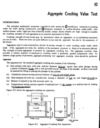
The apparatus for the standard aggregate crushing test consists of the following:
(i) Steel cylinder with open ends, and internal diameter 25.2 cm, square base plate plunger having
a piston of diameter ~ with a hole provided across the stem of the plunger ~o that a rod could
be inserted for lifting or placing the plunger in the cylinder.
(ii) Cylindrical measure having internal diameter of p.5 cm and height 18 cm.
(iii) Steel temping rod with one rounded end, having a diameter of 1£ cm and length 45 to 60 cm
(iv) Balance of capacity ~ kg with accuracy upto I g.
(v) Compressions testing machine capable of applying load of 40 tonn£s, at a uniform rate of loading
of 4 tonns§ per mjnute.
z
u
,~~l
s: ~
<t
ez
l'61~u
till E
u -4'~~ "-
~
o
~
T CYLINDRICAl
MEASURE STeEL TAMPING
ROO
2. Procedure
The aggregate passing 12.5 mm IS sieYF and retained on 10 mm IS sjeySiis selected for standard test.
The aggregate should be in surface-dry condition before testing. The aggregate may be dried by heating
at a temperature lOO:>Cto llO°C for a period of 4 hours and is tested after being cooled to room
temperature.
The cylindrical measure is filled by the test sample of aggregate in three layers of approximately equal
depth, each layer being tamped~imes by the rounded end of the tamping rod. After the third layer is
tamped. the aggregates at the top of the cylindrical measure is levelled off by using the tamping rod as a
straight edge. About ~ of aggregate is required for preparing two test samples. The test sample thus
taken is then weighed. The ~am¥ wejght of the sample is taken in the repeat test.
The cylinder of the test apparatus is placed in position on the base plate; one third of the test sample
is placed in this cylinder and tamped 25 times by the tamping rod. Similarly, the other two parts of the
test specimen are added, each layer being subjected to 25 blows. The total depth of the mater;'l in the
-cylinder after tamping s}lall however be .uu.n. The surface of the aggregates is levelled and the plunger
inserted so that it rests on this surface in level position. The cylinder with the test sample and plunger
in position is placed on compression testing machine. Load is then applied through the plunger at a
uniform rate of ~ tonnes per minute until the total load is •• 0 tonnes, and then the load is released.
4
Aggregates including the crushed portion are removed from the cylinder and sieved on a 2 36 mm IS ~jeve.
The material which passes this sieve is collected.
•
The above crushing test is repeated on second sample of the same weight in accordance with above test
procedure. Thus two tests are made for the same specimen for taking an average value.
Total weight of dry sample taken = WI g.
IS sieve = W2 g.
.
The aggregate crushing value is defined as a ratio of the weight, of fines passing the specified IS sieve
to the total weight of the sample expressed as a percentage. The value is usually recorded up to the first
·decimal place.
100 W2
ggregate crushing value =
WI
Results
.The mean of the crushing value obtained in the two te<;tsis reported as the aggregate crushing value.
Determination of Ten Percent Fines Value
The 'ten percent fines' value is a measure of resistance of tbe aggregates to the crushing. The apparatus
-and materials used are the same as for tbe standard aggregate crushing test. The test sample in the cylinder
with the plunger in position is placed in the compression testing machine. The load is applied at a uniform
rate so as to cause a total penetration of the plunger of about 20 mm for normal crushed aggregates in
10 minutes. But for rounded or partially rounded aggregates, the load required to cause a total penetration
·of 15 mm is applied where as for honeycomb~d aggregate like expanded shales-or slags that for a total
penetration of 24 mm is applied in 10 minutes. After the maximum specified penetratiC:n is reached, the
load is released and the aggregates from the cylinder is sieved on a 2.36 mm IS sieve. The fines passing
this sieve is weighed and is expressed as a percentage by weight of the test sample. This percentage normally
falls in the range of 7.5 to 12.5; but if it does not fall in this range, the test is repeated with necessary
..adjustment of the load.
3. Two tests are carried out at the load (x tonnes) which give the percentage fines between 7.5 and 12.5 and
let tae mean of the percent fines be 'y' for calculating the load required for 10 percent fines.
14x
Load for 10 percent fine = ---
(y + 4)
In general, large size of aggregates used in the test results in higher aggregates crushing value. The
relationship between the aggregate sizes and the crushing values will however vary with the type 0'[
specimens tested. When non-standard sizes of aggregates are usnd for the crushing test, (i.e. aggregate
larger than 12.5 mm or smaller than 10 mm) the size of the cylinder, quantity of material for preparation
of specimen size of IS sieve for separating fines and the amount and rate of compaction shall be adopted as
given in Table 10.1.
Aggregate size Diameter of Quantity of material and Size of IS sieve
Passing sieve I Retained on cylinder to
be used,cm
preparation of test
sample
Loading for separating
fines
size, mm sieve size, mm
25 20 15
* (standard ••••••
Standard method +Standard loading 4.75 mm
cylinder) Standard loading 3.35 mm
20 12.5 Standard method
"
Metal measure 5 cm dia Rate of loading one
& 9 cm height tamping tonne per min. upto
10 6.3 7.5- rod 8mm dia 30cm long a total load of 10 1.70 mm
depth of material in 7.5 tonnes.
cm cylinder after tamp-
ing 5 cm
6.3 4.75 7.5 as above as above 1.18 mm
4.75 3.35 7.5 as above as above 850 microns
3.35 2.36 7.5 as above as above 600 microns
·Standard cylinder as given in Figure 10.1.
"Standard method of preparing sample as given in procedure.
+Standard loading as given in procedure.
The aggregate sample for conducting the aggregate crushing test for the first time is to be taken by
volume in the specified cylindrical measure by tamping in a specified manner and the weight of the sample
is determined. When the test is repeated using the same aggregate, it is sufficient to directly weigh and
take the same weight of sample This is because it is necessary to keep the volume and height of the test
specimens in the aggregate crushing mould constant when testing any aggregate sample"so that the test,
conditions remain unaltered. If the quantity of test sample to be taken is specified by weight, the volume
and hence the height may vary depending on the variation in specific gravity and shape factors of different
aggregates.
When aggregates are not available, crushing strength test may be carried out on cylindrical specimen
prepared out of rock sample by drilling, sawing and grinding. The specimen may be subjected to a slowly
4. increa~ing compressive load until failure to find the crushing strength in kg/cm2• However, ~ this test is
seldom carried out due to difficulty in preparing specimens and not getting reproducible results. On the
contrary, the aggregate crushing test is simple, rapid and gives fairly consistent results.
Applications of Aggregate Crushing Test
It
The aggregate crushing value is an indirect measure of crushing strength of the aggregates.'" Low
aggregate crushing value indicates strong aggregates, as the crushed fraction is low. ~hus the test can be
used to assess the suitability of aggregates with reference to the crushing strength for various types of
pavement components. The aggregates used for the surface course of pavements should be strong enough
to withstand the high stresses due to wheel loads, including the .. steel tyres of loaded bullock-carts.
However as the stresses at the base and sub-base courses are low aggregates with lesser crushing strength
may be used at the lower layers of th~ pavement.
~Indian Roads Congress and IS) have specified that the aggregate crushing value of the coarse
aggregates used for cement concrete pavement at surface should not exceed 30 percent. For aggregates
used for concreteothet than for wearing surfaces, the aggregate crushing value shall not exceed 45 percent,
according to the ISS. However aggregate crushing values have not been specified by the IRC for coarse
aggregates to be used in bituminous pavement construction methods.
1. Methods for Sap:tpling and Testing of Mineral Aggregates, Sands and Fillers BS 812, British Standards
Institution.
2. Indian Standard I Methods of Test for Aggregate for Concrete, IS: 2386 Part IV, Indian Standards
Institution.
3. Indian Standard Specification for Coarse and· Fine Aggregates from Natural Sources for concrete,
IS : 383 Indian Staadards, Institution.
4. Standard Specification and Code of Practice for Construction of Concrete Roads, IRC: 15, 1970,
Indian Roads Congress.
5. Bituminous Materials in Road Construction, D.S.I.R., H.M.S.O., London.
How is the crushing strength test carried out on cylindrical stone specimen? Why is the test not
carried out commonly ?
Explain aggregate crushing value. How would you express?
Briefly explain the aggregate crushing value test procedure.
What is the specified standard size of aggregates? How is the aggregate crushing value of non-standard
size aggregate evaluated ?
Aggregate crushing value of material A is 40 and that of B is 25. Which one is better ~nd why?
What are the applications of aggregate crushing test?
What are the recommended maximum values of aggregate crushing value for the aggregates to be used
in base and surface courses of cement concrete?
What are the uses and applications of the aggregate crushing test?
5. Sample Total weight of dry
Weight of fines
passing 2.36 mm IS
Aggregate crushing value
= W 2 X tOO [Cent
I Average aggregate
crushing value-
Number Sample. WI g Sieve. WI g WI pc Average of cot (4)
6. 12
Aggregate Impact T.est
i
INT~~u:~~:sI~~ the property of a material to resist impact. Due to traffic loads, the road stones are]
subjected to the pounding action or impact and there is possibility of stones breaking into smaller piece~'l
i
The road stones should therefore be tough enough to resist fracture under impact. A test designed to l
evaluate the toughness of stones i.e., the resistance of the stones to fracture under repeated impacts may bel
called an impact test (0' mad stnnes. l.
Impact test may either be carried out on cylindrical stone specimens as in Page Impact test or on stone 1
aggregates as in Aggregate Impact test. The Page Impact test is not carried out now-a-days and has also J.'
been omitted from the revised British Standards for testing mineral aggregates. The Aggregate Impact test 1
has been standardised by the British Standards Institution and the Indian Standards Institution.}
The aggregate impact value indicates a relative measure of the resistance of an aggregate to a sudden
i
i
shock or an impact, which in some aggregates differs from its resistance to a slow compressive load. The ~
I
method of test covers the procedure for determining the aggregate impaet value of coarse aggregates.
Apparatus
The apparatiis consists of an impact testing machine, a cylindrical measure, tamping rod, IS sieves,
balance and oven.
(a) Impact testing machine,. The machine consists of a metal base with a plane lower surface supported
well on a firm floor, without rocking. A detachable cylindrical steel cup of internal diameter 10). em and
depth~ is rigidly fastened centrally to the base plate. A metal hammer of weight between ll£ and
W. kg having the lower end cylindrical in shape, ~m in diameter and 5 em IQng, with 2 mm charpfer
at the lower edge is capable of sliding freel)' between vertical guide!', and fall concentric over the cup.
There is an arrangement for raising the hammer and allowing it to fall freely between vertical guides from
a height of 38 crr on the test sample in the cup, the height of fall being adjustable upto~. A key is
provided for supporting th~ hammer while fastening or removing the cup. Refer Figure 12.1.
(b) Measure: A cylindrical metal measure having internal diameter 1,5 em and depth.1.£!p for
measuring aggregates.
(c) Tamping rod: A straight metal tamping rod of circular cross section,~ in diameter and~
long, rounded at one end
(d) Sieve: IS sieve of sizes 125 !J1Ql, 10 mm and 2 36 mm for sieving the aggregates.
(e) Balance: A balance of capacity not less than 500 g to weigh accurate upto 0.1 g.
<f) Oven: A thermostatically controlled drying oven capable of maintaining constant temperature
~etween 100°C and 100°C.
Procedure
The test sample consists of aggregat.es passing ~m sieve and retained on 10 mm sieve and dried in
7. an oven for four hours at a temperature 100°C to llO·C and cooled. Test aggregates are filled upto about
one-third full in the cylindrical measure. and tamped ,25 times with lounded end of the tamping rod
Further quantity of aggregates, is then added upto about two-third full in the cylinder and 25 strokes of the
tamping rod are given. The measure is now filled with the aggregates to over flow, tamped 25 times.
The surplus aggregates are struck off using the tamping rod as straight edge. The net weight of the
aggregates in the measure is determined to the nearest gram and this weight of the aggregates is used for
carrying out duplicate test on the same material. The impact ma,chine is placed with its bottom plate fiat
on the floor so that the hammer guide columns are vertical. The cup is fixed firmly in position on the base
of the machine and the whole of the test sampie from the cylindrical measure is transferred to the cup and
compacted by tamping with ~5 strokes.
The hammer is raised until its lower face is J§. cmal2gve the upper surface of the aggregates in the cup,
and allowed to fall freely on the aggregates. The test sample is subjected to a total of J 5 sucb blowli, each
being delivered at an interval of not less than one second. The crushed aggregate is then removed from
the cup and the whole of it sieved on the ~6 mm sieve until no further significant amount passes. The
fraction passing the sieve is weighed accurate to!!J..& The fraction retained on the sieve is also weighed
and if the total weight of the fractions passing and retaind on the sieve is added it should not be less than
the original weight of the specimen by more than one gram; if the total weight is less than the original by over
one gram, the result should be-discarded and a fresh test made.
The above test is repeated on fresh aggregate sample.
Calculation
The aggregate impact value is expressed as the percentage of the fines formed in terms of the total
weight of the sample.
Let the original weight of the oven dry sample be WI g and the weight of fraction passing 2.36 mm
I~ sieve be W 2 g.
8. 100 W~
Aggregate impact value = --- percent.
Wl
This is recorded correct to the first decimal place.
Results
The mean of the two results is reported as the aggregate impact value of the specimen to the nearest
whole number.
Aggregate impact value is to classify the stones in respect of their toughness property as indicated
below:
Aggregate impact values
< 10% Exceptionally strong:. 10-20% Strong
10-30% Satisfactorily for road surfacing; > 35% Weak for road surfacing
Chief advantage of aggregate impact test is that test equipment and the test procedure are quite
simple and it determines the resistance to impact of stones simulating field condition. The test can be
performed in a short time even at construction site or at stone quarry, as the apparatus is simple and
portable.
Well shaped £!!bical stones provide higher resistance to impact when compared with flaky and
elongated stones.
It is essential that the first specimen to be tested from each sample of aggregate is equal in volume;
this is ensured by taking the specimen in the measuring cylinder in the specified manner by tamping in
three layers. If all the test specimens to be tested in the aggregate impact testing mould are of equal
volume, the height of these specimens will also be equal and hence the height of fall of the impact rammer
on the specimens will be equal. On the other hand, if equal weight of different aggregate samples are
taken, their volume and height may vary depending upon the specific gravity of the aggregates and
their shape factors.
There is no definite reason why the specified rate of application of the blows of the impact rammer
should be maintained
Applications of Aggregate Impact Value
The aggregate impact test is considered to be an important test to assess the suitability of aggreg~tes as.
regards the toughness for use in pavement construction. It has been found that for majority of ~ggregates,
the agAregate crushing and aggregate impact values are numerically similar within close limits. But in the
case of fine grained highly siliceous aggregate which are less resistant to impact than to crushing. the
aggregate impact values are higher (on the average, by about 5) than the agg1egate crushing values. .
Various agencies have specified the maximum permissible aggregate impact values for the different types
of pavements, those recommended by the Indian Roads congress are given in Table 12.1.
For deciding the suitability of soft aggregates in base course construction, this test has been commonly
used. A modified impact test is also often carried out in the case of soft aggregates to find the wet impact
value after soaking the test sample. The recommendations given in Table 12.2 based on work reported by
different agencies; have been made to assess the suitability of soft aggregates for road construction.
9. AGGREGATE IMPACT TEST
TABLE 12.1
Maximum Allowable Impact Value of Aggregate in Different Types of Pavement Material/Layers
Aggregate impact
value, maximum, %
Water bound macadam (WBM), sub-base course
Cement concrete, base course (as per ISO
(i) WBM base course with bitumen surfacing
(ij) Built-up spray grout, base course
Bituminous macadam, base course
(ii) Built-up spray grout, surfacing course
(iii) Bituminous penetration macadam
(iv) Bituminous macadam, binder course
(v) Bituminous surface dressing
(vi) Bituminous carpet
(vii) Bituminous! Asphaltic concrete
(viii) Cement concrete. surface course
Maximum aggregate impact
Condition of value, perceilt
sample
I Sub-base and I
base Surface course
Dry
Wet
Bituminous Materials in Road Construction, D.S I.R. H.M.S.O., London.
~oad Aggregates. their uses and testing BH. Knight, and R.G. Knight, Edward Arnold Co., London.
Indian standard Methods of Test for Aggregate for Concrete, IS: 2386 part IV Indian Standards
'i Institution.
Indian Standard Specification for Coarse and Fine Aggregate from Natural Sources, IS : 383,
~lndianStandard Institution.
10. AGGREGATE IMPACT TEST
TABLE 12.1
Maximom Allowable Impact Value of Aggregate in Different Types of Pavement Material/Layers
Aggregate impact
value, maximum, %
Water bound macadam (WBM). sub-base course
Cement concrete, base course (as per 151)
(i) WBM base course with bitumen surfacing
(ij) Built-up spray grout, base course
Bituminous macadam, base course
(i) WBM, surfacing course
(ii) Built-up spray grout, surfacing course
(iii) Bituminous penetration macadam
(iv) Bituminous macadam, binder course
(v) Bituminous surface dressing
(vi) Bituminous carpet
(vii) Bituminous! Asphaltic concrete
(viii) Cement concrete. surface course
Maximum aggregate impact
Condition of value, percent
sample
I Sub-base and base I Surface course
Dry
Wet
I. Bituminous Materials in Road Construction, D.S I.R. H.M.S.O., London.
2. Road Aggregates. their uses and testing BH. Knight, and R.G. Knight, pdward Arnold Co., London.
3. Indian standard Methods of Test for Aggregate for Concrete, IS: 2386 part IV Indian Standards
Institution.
-4:. Indian Standard Specification for Coarse and Fine Aggregate from Natural Sources, IS : 383,
.Indian Standard Institution.
5. Tentative Specification [For Various Types of Construction Methods], Indian Roads Congress.
6. Standard Specifications and code of Practice for Construction of Concrete Roads, IRC: 15 - 1970,
Indian Roads Congress.
7. Methods for sampling and Testing of Aggregates, Sands and Fillers, BS : 812, British Standard Institution.
8. Report of the Seminar on Low Cost Roads and Soil Stabilization, E.C.A-.F E., New Delhi, 1958~
11. What are the advantages of Aggregate IIQpact test <>Ver age Impact test?
P
Briefly mention the procedure of aggregate iqlpa~ test?
How is aggregate imI:lact value expressed?
,
What I!-re the desirable limits of aggregate impact value specified for different types of pavement
~~? ~
.~
Aggregate impact value material A is 20 and that of B is 45. Which one is better for surface course? ~
'i
Why?
&erial
No.
Trialnam: . I
1 Total weight of agregate sample filling the cylindrical
,
measure = WI g.
2 Weight of aggregate' ~sing 2.36 moo sieve after
the test = WI g
3 Weight of aggregaterctained on 2.36 moo sieve after
the test ~ Ws g
•• {WI - W2 + Wa> g "
l. AJlllI"sate
Impact value = percent fines
W .
= 100 _t percent'
Wt
12. Abrasion Test
Due to the movements of traffic, the road stones used in the surfacing course are subjected to wearing
action at the top. Resistance to wear or hardness is hence an essential property for road aggregates,
especially whp.n uled in wearing course. Thus road stones should be hard enough to resist the abrasion
due to the traffic. When fast moving traffic fitted with pneumatic tyres move on the road, the soil particies
present between the wheel and road surface causes abrasion on the road stone. Steel tyres of animal drawn
vehicles which rub against the stones can cause considerable abrasion of the stones on the road surface.
Hence in order to test the suitability of road stones to resist the abrading action due to traffic, tests are
carried out in the laboratory.
Abrasion test on aggregates /lre generally carried out by anyone of the following methods:
(j) Los Angeles abrasion test
(ij) Deval abrasion test
(iii) Dorry abrasion test
Of these tests, the Los Angeles abrasion test is more commonly adopted as the test values of aggregates
have been correlated with performance of studies. The ISI has suggested that wherever possible, LOI
I
Angeles abrasion test should be preferred.
In addition to the above abrasion tests, another test which is carried out to test tbe extent to which the
aggregates in the wearing surface get polished under traffic, is 'Polished Stone Value'test. Samples of
aggregates are subjected to an accelerated polishing test in a machine and a friction test is carried out on
the polished specimen. The results of this test are useful only for comparative purpose and specifications
are not yet available.
Introduction
The principle of Los Angeles abrasion test is to find the percentage wear due to the relative rubbin&
action between the aggregates and steel balls used as abrasive charge; pounding action of these balls also
exist while conducting the test. Some investigators believe this test to be more dependable as rubbing and
pounding action simulate the field conditions where both abrasion and impact occur. Los angeles abrasion
test has been standardised by the ASTM, AASHO and also by the IS]. Standard specification of Los
Angelesabrasion values are also available for various types of pavement constructions.
13. <n opening is provided in the cylinder for the introduction of the test sample. A removable cover of the
opening is provided in such a way that when closed and fixed by bolts and nut, it is dust-tight and the
interior surface is perfectly cylindrical. A removable steel shelf projecting radiaIly 8.8 cm into the
cylinder and extending to the full length of it, is mounted on the interior surface of the cylinder rigidly,
parallel to the axis The shelf is fixed at a distance of 125 cm from the opening. measured along the
circumference in the direction of rotation, Refer Figure 11.1. Abrasive charge, consisting of cast iron
spheres approximately 4.8 cm in diameter and 390 to 445 g in weight are used. The weight of the sphere
used as the abrasive charge and the number of spheres to be used are specified depending on the gradation
of the aggregates tested. The aggregate grading have been standardised as A. B. C, D. E, F, and G for
this test and the IS specifications for the grading and abrasive charge to be used are given in Table 11.1,
IS sieve with l. 70 mm opening is used for separating the fines after the abrasion test.
CROss SECTION
Figure 11.1 Los Angeles Machine
Proct'dure
Clean aggregates dried in an oven at 105-110°C to constant weight. confMming to anyone of the
grading A, to G, as per Table Il.l. is used for the test. The grading or gradings used in the test should be
nearest to the grading to be used in the construction. Aggregates weighing 5 kg for grading A. B, Cor D
and II) kg for gradings E, For G may be taken as test specimen and placed in the cylinder. The abrasive
charge is also chosen in accordance with Table 11.1 depending on the grading of the aggregate and is
placed in the cylinder of the machine. The cover is then fixed dust-tigllt. The machine is rotated at a
speed of 30 to 33 revolutions per minute. The machine is rotated for 500 revolution for gradings A. B, C
and D. for gradings E F and G, it shaIl be rotated for 1,000 revolutions The machine should be balanced
and driven in such a way as to maintain uniform peripheral speed.
After the desired number of revolutions, the machine is stopped and the material is discharged from
the machine taking care to take out entire stone dust. Using a sieve of size larger than I. 70 mm IS sieve,
the material is first separated into two parts and the finer position is taken out and sieved further on a
1.7 mm IS sieve. The portion of material coarser than 1.7 rom size is washed and dried in an oven at
105 to llOQC to constant weight and weighed correct to one gram.
Calculations
The difference between the original and final weights of the sample is expressed as a percentage of the
original weight of the sample is reported as the percentage wear.
14. TABLE 11.1
Specifications for Los Angeles Test
Weight in grams of each test sample in the size range, mm Abrasive charge
~ (Passing and retained on square holes.) Number
:.a 1------;----'-------------------------:--- Weight of
_~ 80-63163-50150-40140-25:25-20120-12.5112.5-lOilO-6.3~6.3-4.751 ::j~-.s;:eres . charge, g
A 1250 1250 1250 1250 12 5090±25
B 2500 2500 II 45134±25
C 8 3330±20
D 6 2500±15
E 2500* 2500· 5000· 12 5000±25
F 5000· 5000· 12 5000±25
G 5000* 12 5000±25
Let the original weight of aggregate =Wlg
Weight of aggregate retained on 1.70 mm IS sieve after the test = W2 g
Loss in weight due to wear = (WI-W2) g
(WI-W2) 100
WI
Result
The result of the Los Angeles abrasion test is expressed as a percentage wear and the average value of
two tests may be adopted as the Los Angeles abrasion value.
It may seldom happen that the aggregates desired for a certain construction project has the same
grading as anyone of the specified gradings. In all the cases, standard grading or gradings nearest to the
gradation of the selected aggregates may be chosen
Different specification limits may be required far gradings E, F and G, when compared with A, B, C
and D. Further investigations are necessary before any such specifications could be made.
Los Angeles abrasion test is very commonly used to evaluate the quality of aggregates for use in
pavement construction, especially to decide the hardness of stones. The allowable limits of Los Angeles
abrasion values have been specified by different agencies based on extensive performance studies in
the field.
The ISI has also suggested that this test should be preferred wherever possible. However, this test may be
considered as one in which r<:sistance to both abrasion and impact of aggregate may be obtained
simultaneously, due to the presence of abrasive charge. Also the test condition is considered more
representative of field conditions. The result obtained on stone aggregates are highly reproducible.
Applications of Los Angeles Abrasion Test
Los Angeles Abrasion test is very widely accepted as a suitable test to assess the hardness of aggregates
used in pavement construction. Many agencics have specified the desira ble limits of the test, tor different
15. methods of pavement construction. The maximum allowable Los Angeles abrasion values of aggregates as
specified by Indian Roads Congress for different methods of ~onstruction are given in Table 11.2.
TABLE 11.2
Maximum Allowable Los Angeles Abrasion Values of Aggregates in Different
Types of Pa,ement Layen
Serial Los Angeles abrasion
No. value, maximum %
Water Bound Macadam (WBM), sub-base course
0) WBM base course with bituminous surfacing )
(ii) Bituminous Macadam base course
(iii) Built-up spray grount base course
(i)
(ii)
WBM surfacing course
Bituminous Macadam binder course
1
(iii) Bituminous penetration Macadam I
(iv) Buil-up spray grout binder course
(i) Bituminous carpet surface course }
(ii) Bituminous surface dressing, single or two coats
(Hi) Bituminous surface dressing, using precoated aggregates
(iv) Cement concrete surface course (as per IRe)
(i) Bituminous! Asphaltic concrete surface course
(ii) Cement concrete pavement surface course (as per ISI)
Introduction
Deval abrasion test was devised to test rock fragments. Later this test has been standardised by ASTM
for finding the rate of wear of stone aggregates. by crushing them to tumble one over other in a rattler in
presence of abrasive charge. Deval abrasion test has also been standardised by ISI as a test for abrasion
of coarse aggregates. In this test also both abrasion and impact take place due to the steel balls used as
abrasive charge.
Apparatus
The apparatus for the test consists of the Deval machine and standard sieve.
The deval abrasion testing machine consists of one or more (generally two) hollew cast iron cylinders
closed at one end and provided with iron cover at the other end, capable of fitting tightly. The inside
diameter of the cylinder is 20 cm and length is 34 cm. The cylinders are mounted on a shaft at an angle
of 30 degrees with the axis of rotation. See figure 11.2. Cast iron or steel spheres of about 4.8 cm
diameter and 390 to 445 g weight are used as abrasive charge. Six such spheres are used as abrasive charge,
their total weight being 2500 ± 10 g.
IS sieves having 1.70 mm square holes are used for sieving the materials after the abrasion test.
Procedure
The test sample consists of dry coarse aggregates made of different percentages of the various sizes
16. conforming to anyone of the gradings given in Table 11.3. The material. is washed dried and separated
to different sizes by sieving. The grading adopted for the test should be the one which most nearly
represents the coarse aggregate to be used for a particular construction project. Crushed gravel conforming
to the above specifications can also be used.
TABLE 11.3
Grading of Aggregates for Deval Abrasion Test
Passing IS sieve. mm Retained on IS sive mm Percentage of sample
20 12.5 25
25 20.0 25
40 25.0 25
50 40.0 25
20 12.5 25
25 20.0 25
40 2~.0 50
20 12.5 50
25 20.0 50
12.5 4.75 50
20 12.5 SO
10 4.75 50
12.5 10.00 50
The weight of the sample to be taken for the test depends on its average specific gravity and is
given in Table 11.4.
Over 2.8 5,500
*2.4 to 2.8 5,000
2.2 to 2.39 4,500
less than 2.2 4,000
17. The sample and the abrasive charge of 6 spheres of total weight 2,500 ± ]0 grams are placed in the
Deval abrasion testing machine and the cover is tightly fixed. The machine is rotated at a speed of 30 to
33 r.p.m for 10,000 revolutions. At the completion of the above number of revolutions, the material is
removed from the machine and is sieved on a 1.70 mm IS sieve. The materia] retained on the sieve is.
washed, dried and weighed to the nearest gram.
Calculation
(0 The loss in weight by abrasion is the difference between the original weight of the test sample
and the weight of material retained on the 1.70 mm IS sieve after the test. The percentage of wear is the
loss in weight by abrasion expressed as a percentage of the original weight of the sample.
Let the original weight of the sample be = WI g
. Weight of material retained on 1.70 mm IS sieve after the abrasion test ~, W2 g
Therelore percentage wear or Deva I abraSion value, %
" . ( ----- lIW2
Ww ) 100
(ii) In the case of crushed gravel (i.e, fragment of gravel having atleast one fractured face) the
percentage by weight of crushed fragments should be determined and the permissible percentage wear is
calculated as given below
W = AL + OOO-A) L'
100
Where W = permissible percentage of wear
A = percentage of uncrushed fragments
L = maximum perCentage of wear permitted by the specifications for aggregates.
consisting entirely of crushed fragments.
(100- A) = percentage of crushed fragments,
and L' = maximum percentage of wear permitted by the specifications of gravel consisting
entirely of crushed fragments.
Results
Duplicate test may be carried out simultaneously by placing similar specimens in the second cylinder
~nd the average values of the two tests may be calculated. The report includes (a) percentage of wear.
(b) percentage of crushed fragments in the test sample and (c) weight and grading of the test sample.
Discussion
When coarse aggregates furnished for the work contains as much as 25 percent of material finer than
12 5 mm but is of such size tbat either grading A, B or C would be used for the abrasion test, a second
abrasion test should be carried out, using grading D, if in the opinion of the engineer, the particles lesser
than 12.5 mm size are not at least equal in hardness to those particles greater than ]2.5 mm size.
The British attrition test using Deval's machine is similar to tbe rattler type of test explained in this
experiment with an exception that no abrasive charge is used. Deval abrasion test is in fact a modified
Deval's attrition test, using abrasive charge. The attrition test which was formerly standardised by BSI has
been omitted, later on as of doubtful value.
Application of Deval Abrasion Test
It has been recommended by the ISl that where ever possible the Los Angeles abrasion test should be
preferred to the Deval abrasion test. The desirable limits of percenta&e wear by the Deval abrasion test
18. nave not been specified by agencies, as this is not a common test Thus the test has limited uses and
applications.
Introduction
This test for the determination of aggregate abrasion value has been standardised by the British
Standards Institution. Formerly the Dorry abrasion test was devised for testing the resistance to abrasion
of cylindrical stone specimens on a rotating metal disc in presence of sand used as abrading agent. Now
the test has been modified so as to find the abrasion value of aggregates.
Apparatus
The apparatus consists of the Dorry abrasion machine and accessories and a set of B.S. test sieves.
The abrasion machine has a flat circular cast iron or steel disc, not less than 60 cm in diameter which can
be rotated in a horizontal plane at a speed of 28 to 30 r.p.m. Two trays made from 3 mm mild steel plate,
of internal dimensions 95 X 57 X 8 mm are used for holding the smaller trays with samples. These two
trays are to be held with their centre points 26 cm from. the centre of disc, diametrically opposite to
each other and with their long side placed in the direction of rotation of the disc. A weight of 2 kg is
used to press the test sample down on the disc. There is a device to feed standard abrasion sand continu-
ously on the disc in front of each test sample at a rate of 680 to 900 g per minute. Two smaller trays made
of mild steel of internal dimensions 92 X 54 X 8 mm are used for keeping the test sample. These smaller
trays can just fit inside the large trays meant for holding the test specimens.
B.S. test sieves of sieve openings 12.5, 8.3,0.85,0.6,0.42,0.3 and 0.15 mm are also necessary to sieve the
aggregate sample, the abrasive sand and fine 'sand. Other apparatus are hot plate, oven, balance, etc.
Procedure
The test sample consists of clean aggregates, passing 12.5 and retained on 8.3 mm sieve, free from
flaky particles, 33 cm3 of such dry aggregates is placed in one of the smaller trays to form a single layer
projecting 5 to 6 mm above the upper edge of the tray. The interstices between the aggregates is filled up
to the level of the top of smaller tray by fine sand passing 0.15 mm sieve. The tray with the aggregate
and fine sand is heated to temperature not less than 80°e.
One of the larger trays is placed on a hot plate and is filled with a molten setting compound. The
setting compound may consist of a mixture of pitch and plaster of Paris of equal proportions. The
compound is allowed to cool till it is viscous enough to enable the tray be inverted and pressed down on the
hot aggregate in the smaller tray The two trays are kept pressed together and cooled till the single layer of
projecting aggregate is firmly held by the setting compound. The test sample of aggregate should have
some what flat upper surface, approximately level with the top edge of the tray. The sand and surplus
setting compound are removed and the tray with the aggregate set-in is weighed.
The sample trays are placed on the abrasion machine. and loaded so that the total load including the
specimen vdth tray is 2 kg. Standard Buzzard Silica sand, at least 75 percent passing 0.6 mm sieve and
all passing 0.85 and retained on 0.3 mm sieve is used as abrasive sand. This abrassive sand is fed
continuously on the disc of the machine which is rotated at a speed of 28- 30 r.p.m. Two samples of test
specimens are tested simultaneously.
After 500 revolutions, the test samples are removed and weighed.
Calculation
The aggregate abrasion value is expressed as the percentage loss in weight due to abrasion! This is
19. calculated from the formula:
Percentage loss in weight = 100 ~-C)
A = weight of oven-dry sample aggregate, g
B = weight of tray with aggregate and setting compound before abrasion, g
C = weight of tray with aggregate and setting compound after the abrasion value.
The mean of the two test results is reported as the aggregate abrasion value.
Discussion
The aggregate abrasion test given above is rapid and easy to perform, except for the preparation of test
specimen, which is difficult and time consuming. This test is however carried out commonly in U.K.
and a few other countries. The Dorry abrasion testing machine which was previously used to test cylindricat
stone specimens can be used for conducting this aggregate abrasion test, with slight modifications for holding
the specimens. In many countries, abrasion of road aggregates is assessed by the Los Angeles abrasion test
as the results of this test have been extensively correlated with performance studies.
Application of British (Dorry) Aggregate Abrasion Test
The presence of sand on the pavement is considered to act as abrading material between the traffic
wheels and the aggregates on the surface, causing addional wea~. Hence the Dorry abrasion test results
should be useful in assessing the suitability of aggregates for use in the pavement surface courses.
The aggregate abrasion value by this test is found to vary from below I for some Flints to ever 15 for
aggregates which may normally be regarded as too soft for use in wearing course of pavements. The
aggregate abrasion value of Granites are found to vary between 3 and 9 where as those of Basalts vary
between 7 and 25 and Lime stones between 17 and 33. Aggregates with abrasion values below 5 may thus
be considered quite hard varieties.
I. Indian Standard Methods of Test for Aggregate for Concrete, IS: 2386 part IV. Indian Standards
Institution.
2. Indian Standard Specification for Coarse and Fine Aggregates from Natural Sources, IS: 383, Indian
Standards Institution.
3, Road Aggregates, Their luses and Testing, B. H. Knight and R. C. Knight., Edward Arnold and
Co., London.
4. Bituminous Materials in Road Construction, D.S.I.R., H.M.S.Q., London.
5. Tentative Specifications [For Various Types of Construction MelhodsJ, IRC: 15, 1970, Indian Roads
Congress!
6. Standard Specifications and Code of Practice for Construction of Concrete Roads. Indian Roads Congress
7. Methods for Sampling and Testing of Mineral Aggregates Sands and Filler::., BS: 812, British
Standards Institution.
20. 3. The abrasion value found from Los Angeles test for aggregates A and B are 3.5 and 1.5 respectively.
Which aggregate is harder? Why? For what types of constructions are these suitable?
5. What are the desirable limits of Los Angeles Abrasion values specified for different types of pavement
surfacings ?
9. Explain briefly how the British (Dorry) aggregates abrasion value is found.
10. Discuss the significance of sand used in the Dorry aggregate abrasion test?
11. How is British (Dorry) aggregate abrasion value expressed? Two materials have abrasion values 3
,.:~ . in,' i ~;
and 10 respectively. Which one is harder and why?
21. (i) Type of aggregate =
(ij) Grading
(iii) Number of spheres used =
(iv) Weight of charge -
(v) Number of revolutions =
Test Number
______ - 1---1---1--2---
2. Weight of specimen after abrasion test, coarser
than 1.70 mm IS sieve = WI g
(WI-WI) 100
3. Percentage wear = WI
(i) Type of aggregate
(ii) Percent crushed fragments -
(Hi) Grading of sample =
(iv) Specific gravity of the sample =
Test Number
Me
1 I 2
Weight of material retained 001.7 mm IS sieve after abrasion
test = W2 g
Percentage wear = (Wl;~I) 100
,
22. Original weight of aggregate = WI g
Weight of worn aggregate after abrasion test = W2 g
Loss in weight due to abrasion = (WI - W2) g
Abrasion value of aggregate = percent Joss in weight
23. 15
Shape Test
INTRODUCTION
---The particle shape of aggregates is determined by the percentages of flaky and elangated particles
contained in it. In the case of gravel it is determined by its angularity number. For base course and
---construction of bituminous and cement concrete types, the presence of flaky and elongated particles are
considered undesirable as they may cause inherent weakness with possibilities of breaking down under
heavy loads. Rounded aggregates are preferred in cement concrete road construction as the workability of
concrete improves. Angular shape of particles are desirable for granular base course due to increased
stability derived from the better interlocking. When the shape of aggregates deviates more from the
spherical shape, as in the case of angular, flaky and elongated aggregates, the void content in an aggregate
of any specified size increases and hence the grain size distribution of a graded aggregate has to be suitably
altered in order to obtain minimum voids in the dry mix or the highest dry density. The angularity
-l1UIDber denotes the void content of single sized aggregates in excess of that obtained with spherical
--!ggregates of the same size. Thus angularity number has considerable importance in the gradation
requirements of various types of mixes such as bituminous concrete and soil-aggregate mixes.
Thus evaluation of shape of the particles, particularly with reference to flakiness, elongation and
angularity is necessary.
The flakiness index of aggregates is the percentages by weight of particles whbse least dimension
(thickness) is less than three-fifths (0.6) of their mean dimension. The test is not· applicable to sizes smaller
than 6.3 mm.
Apparatus
The apparatus consists of a standard thickness gauge shown in Figure 15.1, IS sieves of sizes 63, 50, 40,
i .0
~ .O'2~~t:r
I~ .~rm
~: ·1 i ~ ro;I:'~~
::t
I ~
j 19'50bTQ2SI-25~
L 13.50
1-33.90-l 27.00 _ 70;;;;) :-r
____________________________________
;!}
6/11", THICk "'.S.SHEET
ROLLED OVER 8 /11Mt/> BAIl
Al.l. OI"'ENSlONS IN 11I'"
24. Procedure
The sample is sieved with the sieves mentioned in Table 15.1. A mlD1mUm of 200 pieces of each
fraction to be tested are taken and weighed = WI g. In order to separate flaky materials, each fraction is
then gauged for thickness on a thickness gauge shown in Figure 15.1 or in bulk on sieves having elongated
slots. The width of the slot used should be of the dimensions specified in column (3) of Table 15.1 for the
appropriate size of material. The amount of flaky material passing the gauge is weighed to an a<lCuracyof
at least 0.1 percent of the test sample.
Size of aggregate
(a) Thickness gauge (b) Length gauge
(0.6 times the mean sieve), (1.8 times the mean
Passing through Retained on mm sieve), mm
IS sieve mm IS sieve, mm
1 2 3 4
f 63.0 50.0 33.90
~ 50.0 40.0 27.00 81.0
~~.
40.0 25.0 19.50 58.5
i' It:
31.5 25 () 16.95
~
25.0 200 13.50 40.5
20.0 16.0 10.80 324
16.0 12.5 8.55 25.6
12.5 10.0 675 20.2
10.0 6.3 489 14.7
In order to calculate the flakiness index of the entire sample of aggregates first the weight of each
" ction of aggregate pasSing and retained on the specified lttf of sieves is noted. As an example let 200
. • s of the aggregate passing 50 mm sieve and retained on 5(}mm sieve be = WI g. Each of the particle
m this fraction of aggregate is tried to be passed through the slot of the specified thickness of the thickness
Ule; in this example the width of the appropriate gauge of the thickness gauge is
:"I; (50+40)
--2- X 0.6 = 27.0 mm gauge.
the weight of the flaky material paassing this gauge be WI g. Similarly the weights of the
c' ions passing and retained the specified sieves, WI, W2, Ws etc. are weighed and the total weight
"+ +
W2 + '"
W3 = W g is found. Also the weights of material passing each of the specified thickness
ae are found = WI, W2, Ws... and the total weight of material passing the different thickness gauges
, r+ W2 + Ws + '" = w g is found. Then the flakiness index is the total weight of the flaky material
~},ingth~ various thickness gauges expressed as a per~ntage of the total weight of the sample gauged.
. ~
· I' d (WI +W2+WS+ ... ) 100 ' , 10 w
Fl a k mess n ex = WI + Wa + Ws+... percent c=: 0 W percent.
25. ELONGATION INDEX
~~
The elongation index of an aggregate is the percentage by weight of particles whose greatest dimension
(length) is greater than one ftRd foUl' fifth timos"<1.8 times) their mean dimension. The elongation test is not
applicable to sizes smaller th"ln 6.3 mm.
----
Apparatus
The apparatus consists of the length gauge shown in Figure J 5.2, sieves of the sizes specified in Table
15.1 and.a balance.
Procedure
The sample is sieved through the IS sieves specified in Table 15.1. A minimum of 200 pieces of each
fraction is taken and weighed. In order to separate elongated material, each fraction is then gauged
individually for length in a length gauge (See Figure J 5.2) The gauge lengths used should be those
specified in column 4 of the. Table for the appropriate material. The pieces of aggregates from each
fraction tested which cOl1ldnot pass through the specified gauge length with its long side are elongated
particles and are collectejd separately to find the total weight of aggregates retained on the length gauge
from each fraction. Th~ total amount of elongated material retained by the length gauge are weighed to an
accuracy of atleast 0.1 percent of the weight of the test sample.
:;'~!;"EG
~~~~-
-110 I
..,110
12.5 16
12.5.
I ao
16
I 25
20.
1 40
25
I
.
sa
40
,
I
~._+-~fJ]
.~Jl,m·"1r-
LJJJJLJlJL
-11
~'~I-Z
----------------
~~r: ~ .J
In order to calculate the elongation index of the entire sample of aggregates, the weight oJ aggregates
which is retained on the specified gauge length from each fraction is noted. As an example, let 200 pieces
of the aggregate passing 40 mm sieve and retained 25 mm sieve weight Wl g. Each piece of these are tried
to be passed through the specified gauge length of the length gauge, which in this example is
-
- +
(40 2 25) x I .8 - 585 mm
- .
with its longest side and those elongated pieces which do not pass the gauge are separated and the total weight
determined = WI g. Similarly the weight of each fraction of aggregate passing and retained on specified
sieves sizes are found, WI, W2, Ws ... and the total weight of sample determined = WI W2 Ws + + +
...= Wg. Also the weight of material from each fraction retained on the specified gauge length are
found = Xl, XI, xs· •. and' the total weight retained determined = Xl +
X2 Xs + ... = X g. +
26. The elongation index is the total weight of the material retained on the various length gauges, expressed
as a percentage of the total weight of the sample gauged.
El ongatlOn In d ex = Wl+W2+W3+ ) 100 = 100 W percent
. (Xl+X2+X3 ...
'"
X
ARGULARITY NUMBER
Based on the shape of the aggregate particle, stones may be classified as rounded, angular and flaky.
Angular particles possess well defined edges formed at the intersection of roughly plane faces and are
commonly found in aggregates prepared by crushing of rocks. Since weaker aggregates may be crushed
during compaction, the angularity number does not apply to any aggregate which breaks down during
compaction.
Angularity or absence of the rounding of the particles of an aggregate is a property which is of----
importance because it affects the ease of handling a mixture of aggregate and binder or the workability
of the mix. The determination of angularity number of an aggregate is essentially a laboratory meth~
intended for comparing the properties of different aggregates for mix design purposes and for deciding
their gradation requirements.
The degree of packing of particles of single sized aggregate depends on the shape and angularity of the
aggregates. If a number of single sized spherical particles are packed together in the densest form, the
total volume of solids will be 67 percent and the volume of voids 33 percent of the total volume. However
if the shape of the particles of the same size deviatess from the spherical shape to irregular or angular shape,
when they are densely packed the volume of solids decreases resulting in an increase in the volume of
voids. Hence the angularity of the aggregate can be estimated from the properties of voids in a
sample of aggregates compacted in a pa~ticular manner. The angularity number of an aggregate is ~I
amount by which the percentage voids exceeds 33 after being compacted in a prescribed manner. The
angularity number is found from the expression, (67 minus the percent solid volume). Here the value 67 .
represents the percentage volume of solids of most rounded gravel whi:~V~ll~c! have 33 percent voids.
Apparatus
The apparatus consists of (a) a metal cylinder closed at one end and of about 3 litre capacity, the
diameter and height of this being approximately equal, i.e., about .!-5.64e~ia. X 15.64_cm height. It{ S '( (c6
~ (b) A metal tamping rod of circular cross section, 16 mm in diameter and 60 em in length, rounded
i at one end
~.
~,
f (c) A metal~coop of about one liter heaped capacity of size 20 X 10 X 5 cm, and
f ~~ A balance of capacity 10 kg to weigb up to 1.0 g
,'
I';,'. The cylinder is calibrated by determining the weight of water at 27°C required to fill it, so that no
; meniscus is present above the rim of the container. The amount of aggregate available should be sufficient
to provide, after se, aration on the appropriate pair of sieves, at least 10 kg of the predominent size,' as
p
," determined by the sieve analysis on the 20, 16, 12.5, 10, 6.3~ and 4.75 mm IS sieves. The test sample should
r
" consist of aggregate retained between the appropriate pair of IS sieves having square holes from the
following setS':
20 and 16 mm , 16 and 12.5 mm, , 12.5 and 10 mm , 10 and 6.3 mm , 6.3 and 4.75 mm
In case aggregate larger than 20 mm sieve is used for the test, the volume of the cylinder should be
sreater than 3 litres, but when aggregates smaller than 4.75 mm size are used, a smaller cylinder may be
27. 4. Explain Flakiness Index. How is it found?
5. What is Elongation Index? How is it determined in the laboratory ?
6. Discuss the advantages and limitations of rourtded and angular aggregates in different types of
pavements.
7. Explain Angularity Ntimber. 1101 is it found?
8. What are the applications of shape tests?
General description of the aggregate :
Size of aggregate
Weight of the Thickness Weight of Length gauge Weight of
fraction gauge size. aggregate in size, mm aggregates in
Passing Retained on consisting of each fraction each fraction
through IS IS sieve, mm mm
atleast 200 I passing thick- retained on
sieve, 1~1 pieces, g ness gauge, g ___ 6 llength ~auge, g
2 3 4 I 5
63 50 WI= -2J~9a WI =
SO 40 W2= 27.00 W2= 81.0 Xl =
40 25 Ws= 1950 ws = 58.0 X2 =
31.5 25 W4,= 16.95 w,=
25 20 Ws= 13.50 Ws == 40.5 xs=
20 16 W6= 10.80 W6 = 32.4 X4 =
16 12.5 W7= 8.55 W7= 25.5 Xs =
12.5 10.0 Ws= 6.75 Wa= 20.2 X6==
10.0 6.3 W9= 4.89 W9= 14.7 X7 =
Total W W =
FIa k'lness J nd ex - (Wt+ W2+ WS+···) ]00 percent = -W W percent =
_ 100
(Wl+W2+WS+ ... )
Elongation Index = (~,':I:~:~:S ~ .:: .~ 100 percent '= 1~x percent =
ANGULARITY NUMBER
Weight of water filling the cylinder = C g =
Specific gravity of the aggregate = G
____ Particulars I 1
Trial number
Mean I 4
Mean weight of aggregate fitling the cyiinder, Wg =
WOW
Angularity Number = 67 - CG
Remarks
28. 17
Penetration Test
The consistency of bituminous materials vary depending upon several factors such as constituents,
temperature, etc. At temperature ranges between 25 and 50·C most of the paving bitumen grades remain
in semi-solid or in plastic states and their viscosity is so high that they do not flow as liquid. But the
viscosity of most of the tars and cutbacks are sufficiently low at this temperature range to permit these
bituminous materials to be in a liquid state, enabling some of the grades to be mixed with aggregates
even without heating.
Determination of absolute viscosity of bituminous materials is not so simple. Therefore the consistency
of these materials are determined by indirect methods; the consistency of bitumep is determined by
penetration test which is a very simple test; the viscosity of tars and cutback bitumens are determined
indirectly using an orifice viscometer in terms of time required for a specified quantity of material to flow
through an orifice. There is a certain range of consistency of bituminous materials, where-in the material
is too soft for penetration test, but the viscosity is so high that the material can not flow through the orifice
()f the viscometer; the consistency of such materials is measured by 'float test'.
Various types and grades of bituminous materials are available depending on their origin and refining
process. The penetration test determines the consistency of these materials for the purpose of grading them,
by measuring the depth (in units of one tenth of a millimeter or one hundredth of a centimeter) to which
a standard needle will penetrate vertically under specified conditions of standard load, duration and
temperature. Thus the basic principle of the penetration test is the measurement Of the penetration
(in units of one tenth of a mm) of a standard nsedle in a bitumen sample maintainad at 25°C during five
seconds, the total weight of the needle assembly being 100 g. The softer the bitumen, the greater will
be the penetration.
The penetration test is widely used world over for classifying the bitumen into different grades. The
ISI has standardised the penetration test equipment and the test procedure. Even though it is recognised
that the empirical tests like penetration, softening point etc. can not fully qualify the paving binder for
its temperature susceptibility characteristics, the simplicity and quickness of operation of this test can not
be ignored for common use. The concept of the penetration test and the test set up are illustrated in
Figure 17.1.
Apparatus
It consists of items like container, needle, water bath penetrometer, stop watch etc. Following are
the standard specifications as per ISI for the above apparatus.
(0) Container: A flat bottomed cylindrical metallic container 55 mm in diameter and 35 mm or
57 mm in height.
(b) NrGdle' A straight, highly polished cylindrical, hard steel needle with conical end, having the
shape and dimensions as given in Figure 17.2. The needle is provided with a shank approximately 3.0 mm
in diameter into which it is immovably fixed.
29. (c) ~qter-hqtb: A water bath is maintained at 25 ± 1°C containing not less than 10 litres of water,
the sample is immersed to depth not less than 100mm from the top and supported on a perforated shelf
not less than !j0 mm from the bottom of the bath.
(d) fenetrowel«.: It is a~ ~pparatus whic~ allows t~e need.le assembly. of. gross weight I~Si to
penetrate without appreciable fnctlOn for the desued duratlo~ of tIme. The dIal IS .accurately cah rated
to give penetration value in units of one tenth of a mm. ElectTlcally operated automatIc penetrometers are
also available. Typical sketch of penetrometer is shown in Figure 17.3.
-. - - - - ll'E~~E~A.TUIN
100'
tOO, DIAL FOR
MEASURING
TUMEN PENETRATION
START AFTER 5 SEe.
Fig. 17.1 Penetration Test Concept
1.00 TO '.02 DIA.
r ()'94 TO 0.99DlA. •
. .1
0.14 TO 0.1
DlA •
T~
• 01
L . -.-
1-5 .••
:........1
-I ~
20T025
SO APPROX-l
Figure 17.2 Penetration Needle
Procedure
The bitumen is softened to a pouring consistency between 75° and 100°C above the approximate
temperature'at which bitumen softens. The sample material is thoroughly stirred to make it homogenous
and free from air bubbles and water. The sample material is tben poured into the container to a depth at
least 15 mm more than the expected penetration. The sample containers are cooled in atmosphere of
-
temperature not lower than 13°C for one hour. Then they are placed in temperature controlled water bath
at a temperature of 25°9 for a period of one hour.
The sample container is placed in the transfer tray with water from the water bath and placed under
the needle of the penetrometer. The weight of needle, shaft and additional weight are checked. The total
weight of this assembly should be 100Q; Using the adjusting screw, the needle assembly is lowered and
the tip of the needle is made to just touch the top surface of the sample; the needle assembly is clamped
in this position. The contact of the tip of the needle is checked using the mirror placed on the rear of
the needle. The initial reading of the penetrometer dial is either adjusted to zero or the initial reading
is taken before releasing the needle. The needle is released exactly for a period of 5.0 secs. by pressing
the knob and the final reading is taken on the dia.J. At least three measurements are made on this sample
by testing at distance of not less than 10 mm apart. After each test the needle is disengaged and cleaned
with benzene and carefully dried. The sample container is also transferred in the water bath before next
30. testing is done so as to maintain a constant temperature of 25°C. The test is repeated with sample in the
other containers.
Results
The difference between the initial and final penetration readings is taken as the penetration value.
The mean value of three consistent penetration measurements is reported as the penetration value. It is
further specified by ISI that results of each measurement should not vary from the mean value reported abevo
by more than the following :
Repeatability
0-80 4 percent
80-225 5 percent
Above 225 7 percent
Discussion
It may be noted that the penetration value is influenced by any inaccuracy as regards:
(i) pouring temperature
(ii) size of needle
(iii) weight placed on the needle
(iv) test temperature
(v) duration of releasing the penetration needle
It is obvious to obtain high values of penetration if the test temperature and/or weight (place over the
needle) are/is increased. Higher pouring temperatures than that specified may result in hardening of
bitumen and may give lower penetration values. Higher test temperatures give considerably higher
penetration values. The duration of releasing the penetration needle should be exactly 5.0 sees. It is also
necessary to keep the needle clean before testing in order to get consistant results. The penetration needle
should not be placed closer than 10 mm from the side of the dish.
Applications of Penetration Test
Penetration test is the most commonly adopted test on bitumen to grade the material in terms of its
hardness. Depending up un the climatic condition and type of construction, bitumens of different
penetration grades are used. 80/100 bitumen denotes that the penetration value ranges between 80 and 100.
The penetration values of various types of bitumen used in pavement construction in this country range
between ~and~. For bituminous macadam and penetration macadam, Indian Roads Congress suggests
bitumen grades ~0/40, 6Q17Q and §plIOO. In warmer regions lower penetration grades are preferred and in
colder regions bitumen 'with higher penetration values are used.
The,penetration test is not intented to estimate the consistency of softer materials like cutback or tar,
which are usually graded by a viscosity test in an orifice viscometer.
The Indian Standards Institution has classified paving bitumen available in this country into the
following six categories depending on the penetration values. Grades designated 'N (such as A 35) are from
Assam Petroleum and those designated'S' (such as S 35) are from other sources.
I A 90 & S 90 I A 200 & S 200
! 80to100 I 175 to 225
31. 1. Indian Standard Methods for Testing Tar and Bitumen, Determination of Penetration, IS 1203, Indian
Standards Institution.
2. Bituminous Road Construction. Burmah Shell
3~ Asphalts, ESSO
4. Bituminous Materials in Road Construction,D.S.I R., H.M.S.O., London
5. Recommended Practice for Bituminous Penetration Macadam, (Full Grout), Indian Roads Congre.,.,.
6. Indian Standard Specification for Paving Bitumen, IS: 73-1961, Indian Standards Institution.
1. How is penetration value of bitumen expressed ?
2. What are the standard load, time and temperature specified for penetration test.
3. Briefly outline the penetration test procedure.
4. What do you understand by 80/100 bitumen ?
5. What are the effects of: (i) higher test temperature (ii) higher pouring teinperature
(Hi) exposed bitumen, on penetration test results.
(i) Pouring Temperature, ° c =
(ii) Period of cooling in atmosphere, minutes -
(iii) Room temperature, ° c =
(iv) Period of cooling in water bath, minutes! =
(v) Actual test temperature, °c =
Sample No. Sample No.
Readings Test
1
Test
2
Test
3
I
Mean
value
Test
1
Test
2
Test
3 II Mean
value
•
Penetrometer dial reading ( i) initial
(i i) final r
Penetration value
Repeatability, percent
I
32. 18
Ductility Test
In the flexible pavement construction where bitumen binders are used, it is of significant importance
that the binders form ductile thin films around the aggregates. This serves as a satisfactory binder in
improving the physical interlocking of the aggregates. The binder material which does not possess sufficient
ductility would crack and thus provide pervious pavement surface. This in turn results in damaging effect
to the pavement structure. It has been stated by some agencies that the penetration and ductility
properties, go together; but depending upon the chemical composition and the type of crude source of the
bitumens, sometimes it has been observed that the above statement is incorrect. It may hence be mentioned
that the bitumen may satisfy the penetration value, but may fail to satisfy the ductility requirements.
Bitumen paving engineer would however want that both test requirements are satisfied in the field jobs.
Penetration or ductility can not in any case replace each other. The ductility is expressed as the distance
in centimeters to which a standard briquette of bitumen can be stretched before the thread breaks. The
test is conducted at 27 ± 0.5°C and a rate of pull of 50 ± 2.5 mm per minute. The test has been
standardized by the ISI. The ductility test concept is shown in Figure IS!.
7~O.2
END
..,.
1l1=@1;f] 1~.,
Figure 18.1 Ductility Test Concept
Apparatus
The ductility test apparatus consists of items like ~ample (briquette) moulds water bath square-end
trowel or putty knife sharpened on end and ductility machine. Following are standard specifications as
per the ISI for the above items :
(a J Briquette mould: Mould is made of brass metal with shape and dimensions as indicatcd in Figure
18.2. Both ends called clips possess circular holes to grip th6 fixed and movable ends of the tesiing
machine. Side pieces when placed together form the briquette of the following dimensions:
Length
Distance between clips 30mm
Width at mouth of clips 20mm
Cross section at minimum width 10mmxl0 mm
(b) Ductility machine: It is equipment which functions as constant temperature water bath and a
pulling devicc at a precalibrated rate. The central rod of the machine is threaded and through a gear
33. system provides movement to one end where the clip is fi.xed during initial placement. The other clip end
is hooked at the fixed end of the machine. Two clips are thus pulled apart horizontally at a uniform speed
of 50 ± 2.5 mm ger mjnute_ The machine may have provision to fix two or more moulds so as to test
these specimens simultaneously.
Procedure
The bitumen sample is melted to a temperature of 75 to 190°" above the approximate softening point
until it is fluid. It is strained through IS sieve 3D, poured in the mould assembly and placed on a brass
plate, after a solution of glycerine and dextrine is applied at all surfaces of the mould exposed to bitumen.
Thirty to forty minutes after the sample is poured into the moulds, the plate assembly alongwith the
sample is placed in water bath maintained at 27°C for 30 minutes. The sample and mould assembly are
removed from water bath and excess bitumen material is cut off by levelling the surface using hot knife.
After trimming the specimen, the mould assembly containing sample is replaced in water bath maintained
at 2toC for 85 to 95 minuies. The sides of the mould are now removed and the clips are carefully hooked on
the machine without causing any initial strain. Two or more specimens may be prepared in the moulds
and clipped to the machine so as to conduct these tests simultaneously.
The pointer is set to read zero. The machine is started and the two clips are thus pulled apart
4
horizontal1y. While the test is in operation, it is checked whether the sample is immersed in water at depth
of at least !Q.!tm. The distance at which the bitumen thread of each specimen breaks, is recorded (in cm)
to report as ductility value.
Results
The distailce stretched· by the moving end of the specimen upto the point of breaking of thread measured
in centimeters is recorded as ductility va.l;le. It is recomm,ended by IsI that test results should not differ
from mean value by more than the followhig :
Repeatability S. percent
Reproducibility: 10 percent
Discussion
The ductility value gets seriously affected if any of the following factors are varied:
(i) pouring temperature
(ii) dimensions of briquette
(Hi) improper level gjrbriquette placement
(iv) test temperaturl'
(v) rate of pulling.
Increase in minimum cross section of 10 sq, mm and increase in test temperature would record increased
duciility value.
Applications of Ductility Test
A certain minimum ductility is necessary for a bitumen binder. This is because of the temperature
changes in the bituminous mixes and the repeated deformations that occur in flexible pavements due to the
traffic loads. If the bitumen has low ductility value, the bituminous pavement may crack, especially in cold
weather. The ductility values of bitumen vary from 5 to over 100. Several agencies have specified the
minimum ductility values for various types of bituminous pavement. Often a minimum ductility value of
50 cm is specified for bituminous construction.
The minimum ductility values specified by the Indian Standards Institution for various grades 01
bitumen available in India are given below:
34. Source of paving bitumen Minimum ductility
and penetration grade value, cm
Assam petroleum A 25
A 35
A 45
A 65, A 90 & A 200
Bitumen from sources other
than Assam Petroleum S 35
S 45, S 65 & S 90
Indian Standard Method for Testing Tar and Bitumen; Determination of Ductility,
Standards Institution.
Bituminous Road Construction, Burmah Shell.
Bituminous Materials in Road Construction, D S I.R., H.M.S.O., London.
Indian Standard Specification for Paving Bitumen, IS: 73-1961, Indian Standards Institution.
1. Expl" ductility of Bitumen and its significance.
2. How is ductility value expressed ?
3. Outline the ductility test procedure.
••. What is the minimum area of cross section of the ductility specimen ?
S. What are the precautions to be taken while finding the ductility value?
6. What are the factors affecting the ductility test results?
OBSERVATION SHEET
DUCTILITY TEST
(i) Grade of bitumen : =
(ij) Pouring temperature, °C
(iii) Test temperature, °C =
(iv) Periods of cooling, minlltes
(a) in air
(b) in water bath before trimming -
(c) in water bath after trimming
Briquette Number
I (ii)
1. Ductility value (cm)
2. Repeatability percent
3. Reproducibility percent
35. 19
Softening Point Test
Bitumen does not suddenly change from solid to liquid state, but as the temperature increases, it
gradually becomes softer until it flows readily. All semi-solid state bitumen grades need sufficient fluidity
before they are used for application with the aggregate mix. For this purpose bitumen is sometimes cut
back with a solvent like kerosene. The common procedure however is to Iiquify the bitumen by heating.
The softening point is the temperature at which the substance attains particular degree of softening under
specifiedcondition of test. For bitumen, it is usually determined by Ring and Ball test. A brass ring
containing the test sample of bitumen is suspended in liquid like water or glycerine at a given temperature.
A steel ball is placed upon the bitumen and liquid medium is then heated at a specified rate. The
temperature at which the softened bitumen touches the metal plate placed at a specified distance below the
ring is recorded as the softening point of a particular bitumen. The apparatus and test procedure are
standardized by ISI. It is obvious that harder grade bitumens possess higher softening point than softer
grade bitumens. The concept of determining the softening point by ring and ball apparatus is shown in
Figure 191. .•
!
STAR'
Apparatus
It consists of Ring and Ball apparatus.
(a) Weel Balls: They are two in number. Each has a diameter of 9.5 mill and weigh§ 2.5 ± .05~.
(b) Brass Rings: There are two rings of the following dimensions,
Depth 6.4 mm Inside diameter at top
•
lnside diameter at bottom 15.9 mm Outside diameter
Brass rings are also placed with ball guides as shown in Figure 19.2.
(c) Support: The metallic support is used for placing pair of rings.
,
The upper surface of the rings is adjusted to be~mm below the surface of water or liquid contained
in the bath. A distance o{ ~5 wlP between the bottom of the rings and top surface of the bottom plate of
support is provided. It has a housing for a suitable thermometer.