Procuring digital preservation CAN be quick and painless with our new dynamic...
Electricity and magnetism 1
1. ELECTRICITY AND MAGNETISM
ELECTROSTATICS
If a rod of ebonite rubbed with fur, or with a coat-sleeve, it gains the power to attract light
objects (bodies), such as pieces of papaer or tin-foil or a suspended glass beads. The discovery
that a body could be made atttractive by rubbing is attributed to Thales (640-548 B.C) but
discovery is made by chinese long before than f.He seems to have been led to it through the
Greeks' practice of spinning silk with an amber spindle; the rubbing of a spindle in its
bearings caused the silk to adhere to it. The Greek word for amber is elektron, and a body
made attractive by rubbing is said to be ―electrified‖. This branch of Electricity, the earliest
discovered, is called Electrostatics.
Little progress was made in the study of electrification until the sixteenth century A.D. Then
Gilbert, who was physician-in-ordinary to Queen Elizabeth, found that other substances
besides amber could be electrified: for example, glass when rubbed with silk. He failed to
electrify metals, however, and concluded that to do so was imposibble.
More than 100 years later-in 1734- he was shown to be wrong, by du Fay ; du Fay found
that a metal could be electrified by rubbing with fur or wool or silk, but only if it were
held in a handle of glass or amber; it could not be electrified if it were held directly in the
hand. His experiments followed the discovery, by Gray in 1729, that electric charges could
be transmitted through the human body,water,and metals. These are examples of
conductors; glass and amber are examples of insulators.
Positive and Negative Electricity
In the course of his experiments du Fay also discovered that there were two kinds of
electrification in nature: he showed that electrified glass and amber tended to oppose
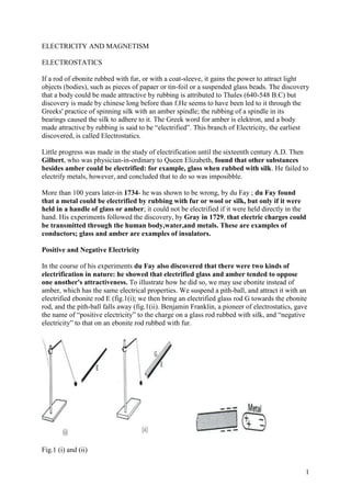
one another's attractiveness. To illustrate how he did so, we may use ebonite instead of
amber, which has the same electrical properties. We suspend a pith-ball, and attract it with an
electrified ebonite rod E (fig.1(i); we then bring an electrified glass rod G towards the ebonite
rod, and the pith-ball falls away (fig.1(ii). Benjamin Franklin, a pioneer of electrostatics, gave
the name of ―positive electricity‖ to the charge on a glass rod rubbed with silk, and ―negative
electricity‖ to that on an ebonite rod rubbed with fur.
Fig.1 (i) and (ii)
1
2. Electrons
Electric charge is a fundamental property of matter. Charge comes in two types, arbitrarily
called positive and negative. Charge is quantized, with one elementary charge—the
magnitude of the electron or proton charge— equal to 1.60X10 19 C, where the coulomb (C)
is the SI unit of charge. Charge is also conserved, in that the algebraic sum of the charges in a
closed system never changes
Towards the end ofthe 19 th century J.J.Thomson dicoverd the existence of the
electron. It is about 1/1840 th of the mass of the Hydrogen atom-and experiments show that it
carries a tiny quantity of negative electricity. Later experiments showed that electrons are
present in all atoms. Electrons exist round nucleus which carry positive electricity. Normally
atoms are electricly neutral which means the total negative charge on the electrons is equal
to the positive charge on the nucleus.
Robert Millikan (1868-1953), in1909 discovered that electric charge is quantized:
any positive or negativecharge can be written as q=ne, where n is positive or negative integer,
e is a constant of nature called the elementary charge.( 1.60x 10 19 C).
The elementary charge e is one of the important constants of nature
q=ne n= 1 , 2 , 3, . . .
Electric charge is quantized.
Electric charge isconserved: the algebraic net charge of any isolated system
cannot change
Gold-leaf Electroscope
One of the earliest instruments used for testing positive and negative charges consisted
of a metal rod A to which gold leaves L were attached (Fig..2). The rod was fitted with a
circular disc or cap B, and was insulated with a plug P from metal case C which screened L
from outside influences other than those brought near to B.
When B is touched by an ebonite rod rubbed with fur, some of the negative charge on the rod
passes to the cap and L; and since like charges repel, the leaves diverge ( Fig.2 (i). If an
unknown charge X is now brought near to B, an increased divergence implies that X is
negative(fig.2(ii). A poistive charge is tested in a similar way; the electroscope is first given a
positive charge and an increased divergence indicates a positive charge.
Figure 2
2
3. Induction and Charging By Induction
We shall now show that it is possible to obtain charges, called induced charges, without any
contact with another charge. An experiment on electrostatic induction, as the phenomenon is
called, is shown in fig.3(i). Two insulated metal spheres A,B are arranged so that they touch
one another, and a negatively charged ebonite rod C is brought near to A. The spheres are
now separated, and then the rod is taken away. Tests with a charged pit-ball now show that A
has a positive charge and B a negative charge fig.3(ii). If the spheres are placed together so
that they touch, it is found that they now have no effect on a pith-ball held near. Their charges
must therefore have neutralized each other completely thus showing that the induced positive
and negative charges are equal. This is explained by the movement of electrons from A to B
when the rod is brought near. B has then a negative charge and A an equal positive charge.
3
4. Fig.3 An experiment on electrostatic induction Fig 4 Electrostatic induction
Fig 3 shows how a conductor can be given a permanent charge by induction, without dividing
it in two. We first bring a charged ebonite rod, say, near to the conductor, (i);next we connect
the conductor to earth by touching it momentarily (ii); finally we remove the ebonite. We then
find that the conductor is left with a positive charge
This phenomenon of induction can again be explained by the movement of electrons. If the
inducing charge is negative, then, when we touch the conductor, electrons are repelled from it
to earth, as shown in fig 3(ii) and a positive charge is left on the conductor. If the inducing
charge is positive, then the electrons are attracted up from the earth to the conductor, which
then becomes negatively charged.
Conductors and Insulators
In some materials, such as metals,tap water and the human body,outer electrons of
atoms are loosly bound. therefore negative charge can move rather freely. We call such
materials conductors. İn other materials, such as glass, chemically pure water and plastic non
of the charge can move freely. We call these materials nonconductors,or insulators.
4
5. İf you rub a copper rod with a wool while holding the rod in your hand you will not be
able to charge the rod,because both you and the rod, are conductors
Again conductors are material in which a significant number of charged particles
(electrons in metals) are free to move. The charged particles in nonconductors,or
insulators are not free to move
Law of Force between two Charges
The magnitude of the force between two electrically charged bodies was studied by Coulomb
in 1875. he showed that, if the bodies were small compared with the distance between them,
then the force F was inversely proportional to the square of the distance r,
1
F (1)
r2
This result is known as the inverse square law, or Coulomb’s law.
It is not possible to verify the law accurately by direct measurement of the force between two
charged bodies. In 1936 Plimton and Lawton showed, by an indirect method, that the power
in the law cannot differ from 2 by more than 2 10-9. We have no reason to suppose,
therefore, that the inverse square law is other than exactly true.
Quantity of Charge
The SI unit of charge is the coulomb (C). The ampere(A), the unit of current, is defined later.
The coulomb is defined as that quantity of charge which passes a section of a conductor in
one second when the current flowing is one ampere.
By measuring the force F between two charges when their respective magnitudes q 1 and q 2
are varied, it is found that F is proportional to the product q 1 q 2
Thus F q 1 q 2 (2)
Law of Force
Combining (1) and (2), we have
q1q 2 q1q 2
F F= k (3)
r2 r2
where k is a constant. For reasons explained later, k is written as 1/4 o, where o is a
constant called the permittivity of free space if we suppose the charges are situated in a
vacuum. Thus
1 q1q 2
F=
4 0 r2
In this expression, F is measured in newtons (N), q in coulombs (C) and r in metres (m).
Now, from (4),
5
6. q1 q 2
o =
4 Fr 2
Hence the units of o are coulomb2 newton -1 metre-2 (C2N-1m-2).
Permittivity
So far we have considered charges in a vacuum. If charges are situated in other media such
as water, then the force between the charges is reduced. Equation (4) is true only in a vacuum.
In general, we write
1 q1q 2
F=
4 r2
Where is the permittivity of the medium. The permittivity of air at 1.005 times that, o,
of a vacuum. For most purposes, therefore, we may assume the value of o for the
permittivity of air. The permittivity of water is about eighty times that of a vacuum. Thus the
force between charges situated in water is eighty times less than if they were situated the same
distance apart in a vacuum.
The unit of o, more widely used, is farad metre-1 ( Fm-1). We shall see later that o
has the numerical value of 8.854 10-12, and 1/4 o then has the value 9 109 approximately.
The elementary charge e is one of the important constants of nature and its charge
( 1.60x 10 19 C).
Particles Charge (C) Mass (kg)
Electron (e) -1,6021917x10⁻¹⁹ 9,1095x10-51
Proton (p) +1,6021917x10⁻¹⁹ 1,67261x10⁻²⁷
Neutron (n) 0 1,67492x10⁻²⁷
Table:1
Fig.3 Vectoral force to show vector form of Coulomb‘s Law
Vector form of Coulomb’s Law
6
7. q1q 2
F= k û r (4) ûr =r
r2
If there are more than 2 charges resultant charges acted on one charge is
F1 = F21 + F31 + F41 (5)
PROBLEMS
1-a)Calculate the value of two equal charges if they repel one another with a force of 0.1 N
1
when situated 50 cm apart in a vacuum. =9 109
4 0
b) What would be the size of the charges if they were situated in an insulating liquid whose
permitivity was 10 times that of a vacuum?
SOLUTION:
1 q1q 2
From F=
4 0 r2
Since q =q here,
9 x10⁹ q 2
0.1=
(0.5) 2
2 0.1x(0.5) 2
or q =
9 x10 9
q=2.7x10 6 C (coulomb),approx.
=2.7 C ( microcoulomb).
b) The permitivity of the liquid =10 0
1 q1q 2
F=
4 0 r2
1 q2
= 2
10 (4 0) r
(0.1) (0.5)2 10
q2 =
9 10 (9)
q= 5 .3 10 6 C=5.3 C
--------------------------------------------------
7
8. 2) Three charged particles are arranged in aline as shown below. Distance between q 1
and q 2 0.30m. Total distance between q 1 and q 3 is 0.50m. k=9.0x 10⁹ N. m 2 / C 2 ;
q 1 = -8 C q 2 =+3 C q 3 = -4 C
Calculate the each electrostatic force on particle 3 (4 C) due to other two charges
SOLUTION:
(9.x109 )(4 x10 6 )(8 x10 6 ).
F 31 = =1.2N repulsive
(0.50) 2
(9 x10⁹ )(4 x10 6 )(3x10 6 )
F32 = =2.7N attractive
(0.20) 2
THE ELECTRIC FIELD
Electric Intensity or Field-strength
An ―electric field‖ can be defined as a region where an electric force is experienced. As in
gravitation or magnetism,
The force exerted on a charged body in an electric field depends on the charge of the
body and on the intensity or strength of the field. If we wish to explore the variation in
intensity of an electric field, then we must place a test charge q 0 at the point concerned
which is small enough not to upset the field by its introduction. The intensity E of an
electrostatic field at any point is defined as the force per unit charge which it exerts at
that point. Its direction is that of the force exerted on a positive charge. q 0
From this definition,
F
E= (6)
q0
lim F
E=
q0 0 q0
F= E q 0
Since F is measured in newtons and q 0 in coulombs, it follows that intensity E has units
of newton per coulomb (NC-1). We shall see later that a more practical unit of E is volt
metre-1 (Vm-1)
j
The electric field at a point charge
8
9. q
E=k (7)
r2
The electric field at a point is a vector giving the electric force per unit charge
that would be experienced by a charge at that point:
F
E=
q0
The electric field of a point charge q is therefore
(8)
We can easily find an expression for the strength E of the electric field due to a point
charge situated in a vacuum .For the force between two such charges.
1 Qq0 F Q
F= E= =
4 0 r2 q0 4 0 r 2
The direction of E is away from the point charge if the charge Q is positive; it is radially
inward if the charge Q is negative.
Continious Charge Distributions
With continuous distributions of charge, the sum over all point charges becomes an
integral, giving
qi
∆E= k e ri
i ri 2
9
10. (9)
Q
Volume charge density ρ= (10)
V
Q
Surface charge density (11)
A
Q
Line charge density (12)
For any finite charge distribution with nonzero net charge, the field approaches that of
a point charge at large distances.
LİNES OF FORCE
A convanient way to visualize the electric field produced by a charge or charge
distribution is to construct a map of the field lines of the force of the field. By other
words electric fields can be mapped out by electrostatic lines of force, which may be
defined as a line such that the tangent to it is in the direction of the force on a small
positive charge at that point. Arrows on the lines of force show the direction of the force
on a positive charge; the force on a negative charge is in the opposite direction.
10
11. Fig.5
Fig.6
3) An electron of charge 1.6 10-19 C is situated in a uniform electric field of intensity
1200 volt cm-1. Find the force on it, its acceleration, and the time it takes to travel 2 cm
from rest (mass of electron, m,=9.10 10-31 kg )
Force on electron F= eE
Now E= 1200 volt cm-1= 120 000 volt m-1
F = 1.6 10-19 1.2 10 5
=1.92 10-14 N (newton)
F 1.92 x10 14
Acceleration, a= = 31
= 2.12 10 16 m s-2 ( metre second-2)
m 9.1x10
11
12. Time for 2 cm travel is given by
1 2
s= at
2
2s 2 0.02
t= = = 1.3 10-9 seconds.
a 2.12 10(16)
-------------------------------------------------
4) Calculate the magnitude and direction of the electric field at a point P which is 30 cm to
the right of a point charge q=-3x 10 6 C k=9.0x 10⁹ N m 2 /C 2
30 cm------
• P
6
q=-3x 10 C E
SOLUTION: the magnitude of the electric field due to sıngle poınt charge ıs gıven
q (9.0 X 10⁹ )(3.0 X 10 6 )
E=k 2
= 2
=3.0X 10⁵ N/C
r (0.30)
Direction of the electric field is toward the charge q
---------------------------------------
5) Determine the magnitude of the electric force on the electron of a hydrogen atom
exerted by the proton Asume the distance between electron orbits and proton is
r= 0.53x 10 10 m., k=9.0x 10⁹ N. m 2 / C 2 ;
SOLUTION:
1 q1q 2
From F=
4 0 r2
19
Since q 1 =q 2 =1.6x10 C here
(9 x10⁹ )(1.6 x10 19 )(1.6 x10 19 )
F= 10 2
=8.2x10 8 N
(0.53x10 )
-----------------------------------------------------------
6) The Earth, which is an electrical conductor,carries a net charge of Q= - 4.3x10 5 C
distributed approximately uniformly over its surface . Find the surface charge density and
caculate the electric field at Earth‘s surface. Earth‘s radius R=6.37x10 6 m
SOLUTION:
Q Q 4.3x10⁵
Earth‘s surface charge density = = = =-8.43x10 10
C/m 2
A 4 R 2 4 (6.37 x10⁶ ) 2
12
13. .A 8.43 x10 10
E.A= E = =-95 N/C
8.85 x10 12
Where the minus(-) sign indicates that the field direction is downward
ELECTRIC FLUX
Before discussing Gauss‘s law itself we first discuss the concept of flux
Flux from a Point Charge
We have already shown how electric fields can be described by lines of force. It can be
said that the density of the lines increases near the charge where the field intensity is high.
The intensity E at a point can thus be represented by the number of lines per unit area
through a surface perpendicular to the lines of force at the point considered. A
surface area A through which auniformelectric field E passes
Fig.7
Fig.8
The electric flux , through this surface is defined as the product.
=ExA (13)
"number of field lines crossing a surface." We call this quantity the electric flux, Ф,
through the surface
If the area is not perpendicular to E but rather makes an angle θ fewer field lines will
pass the area. In this case the electric flux through the surface as
=ExA= ExAcos θ (14)
13
14. Fig.9
7) +1 C charge in the center of sphere whose radius 1m..Find the flux emerging from
the sphere. k=8.89x 10⁹ N. m 2 / C 2
SOLUTION:
Electric field at the surface of the sphere
Q 1x10⁶ C
E=k 2 =(8.89x 10⁹ N. m 2 / C 2 ) 2
=8.99x 10³ N/C
r (1m)
ФE =E.A= E(4 r 2 ) A=4 r 2 =12.6 m 2
ФE =E.A= E(4 r 2 )=(8.99x 10³ N/C)12.6 m 2 =1.13x 10⁵ N. m 2 / C 2
8)Three charges -1 µC, 2 µC and 3 µC are placed respectively at the corners A, B, C of an
equilateral triangle of side 2 metres. Calculate (a) the potential, (b) the electric field, at a point
X which is half-way along BC.
=
= 18 x 103 V.
14
15. VA = =
= - 5 x 10³ V (approx.)
= (18+27-5) x 103 V
= 40 x 103 V.
EB = =
= 18 x 103 V m-1.
EC = 27 x 103 V m-1.
EA = =
= 3 x 10³ V m-1.
E2 = EA2 + (EC - EB)2
= (9 + 81) x 106
= 90 x 106
E =3 x 10³ V m-1 = 9.5 x 10³ V m-1.
Tan = = =
= 18º 25´.
GAUSS’S LAW
We can in preciple determine theelectric field due to any given distribution of electric
charge using Coulmb‘s law. The total electric field at any point will be the vector sum(or
integral) of contributions from all charges present
E= E1 + E 2 +….. E= dE
Except for some simple cases, the sum or integral can be quite complicated to evaluate.
In some cases , theelectric field due to given charge distribution can be calculated
more easily using Gauss‘s law.The major importance of Gauss‘s law is that it gives us
additional insight into the nature of electrostatic fields and more general relationship
15
16. between charge and field. If a surface is curved, then we divide the surface into many
small patches, each small enough that it's essentially flat and that the field is essentially
uniform over each. If a patch has area dA, then Equation below gives the flux through it:
dФ = E • dA. (15)
where the vector dA is normal to the patch (Fig. 10). The total flux through the surface is
then the sum over all the patches. If we make the patches arbitrarily small that sum
becomes an integral, and the flux is
Fig.10
The magnitude of electeric field on the surface of sphere is the same as E = keq/r2
For ΔAi It can be written
Net flux through Gauss surface
In many cases (in particular) we deal with the electric flux through closed surface
= E.dA Gauss’s Law (16)
Consider a sphere of radius r drawn in space concentric with a point charge. The value of
electric field E. It can be written at this place. dA.=A= 4πr2
The total flux through the sphere is, =ExA
1
The net flux through the sphere is ke= therefore
4 0
16
17. q q
ФE = E(4 r 2 )= (4 r 2 )=
4 r2 0 0
q q ch arg e.inside.sphere
ФE = ФE = = (1)Gauss’s Law
0 permittivity
(17)
The electric flux through any closed surface is proportional to the charge enclosed by
that surface.
This demonstrates the important fact that the total flux crossing any sphere drawn outside
and concentrically around a point charge is a constant. It does not depend on the distance
from the charged sphere. It should be noted that this result is only true if the inverse
square law is true.
Field due to Charged Sphere
q
The flux passing through any closed surface whatever its shape, is always equal to
where
q is the total charge enclosed by the surface. This relation, called Gauss‘s Law, can be
used to find the value of E in other common cases.
(1).Outside a charged sphere
The flux across a spherical surface of radius r, concentric with a small sphere carrying a
charge q is given by,
q q
Flux= E 4 r2 = E=q /4 r 2 (18)
Fig.11
17
18. This is the same answer as that for a point charge. This means that outside a charged
sphere, the field behaves as if all the charge on the sphere were concentrated at the
centre.
Fig.12 Two gaussian surfaces surrounding a spherical charge
distribution. Surface 1 lies outside the distribution, and encloses all the charge q. Surface 2
lies inside the distribution, and encloses only part of the charge
(2)Inside a charged empty sphere
Fig.13 Flux and Electric field inside a charged empty sphere
Suppose a spherical surface A is drawn inside a charge sphere, as shown in fig. 12 Inside
this sphere the flux is zero.. Hence. E must be zero everywhere inside a charged
sphere.
E=0 (19)
The electric field is zero inside a conductor ( E=0 ) in electrostatic equilibrium. If
a conductor in electrostatic equilibrium carries a net charge, all excess charge resides on
the conductor surface.
18
19. (3) Outside a charged Plane Conductor
Now consider a charged plane conductor with a surface charge density of coulomb
metre-2.
Applying equation
ch arg e.inside.surface
E area
Now by symmetry, the intensity in the field must be perpendicular to the surface. Further,
the charges which produce this field are those in the projection of the area on the surface .
The total charge here is thus .A coulomb
.A
E.A=
E (20)
Field Round Points and The Action of Points,
we saw that the surface-density of charge (charge per unit area) round a point of a conductor
is very great. Consequently, the strength of the electric field near the point is very great. The
intense electric field breaks down the insulation of the air, and sends a stream of charged
molecules away from the point,by other words charge leaks away from a sharp point through
the air. This mechanism of the breakdown, is called a ‗corona discharge’. Corona
breakdown starts when the electric field strength is about 3 million volt metre-1. the
corresponding surface-density is about 2.7 10-5 coulomb metre-2
In all types of high-voltage equipment sharp corners and edges must be avoided, except
where points are deliberately used as electrodes. Otherwise, corona discharges may break out
from the sharp places. All such places are therefore enlarged by metal globes, these are called
stress-distributors.
POTENTIAL IN FIELDS
When an object is held at a height above the earth it is said to have potential enrgy. A
heavy body tends to move under the force of attraction of the earth from a point of great
19
20. height to one of less, and we say that points in the earth‘s gravitational field have potential
values depending on their height.
Electric potential is analogous to gravitational potential, but this time we think of points in
an electric field. Thus in the field round a positive charge, for example, a positive charge
moves from points near the charge to points further away. Points round the charge are said
to have an electric potential.
Electric potential in the space is described potantial energy per unit of charge at that point
E
V= P (21)
q
POTENTIAL DIFFERENCE
Let us consider two points A and B in an electrostatic field, and let us suppose that the
force on a positive charge q has a component in the direction BA. Then if we move a
positively charged body from B to A, we do work against this component of the field E.
We define the potential difference between A and B as the work done in moving a unit
positive charge from B to A. We denote it by the symbol VAB
W AB
VAB = V B - V A =(22)
q
Fig.14 The work required to move a charge q from A to B in a uniform electric field is
qE .
We define the potential difference ∆V between two points in an elektrik field as
WORK AND ENERGY
The work done will be measured in joules(J). The unit of potential differences is called the
volt and may be defined as follows: the potential difference between two points A and B
is one volt if the work done in taking one coulomb of positive charge from B to A is one
joule.
From this definition, if a charge of q coulombs is moved through a p.d. of V volt, then the
work done W in joules is given by
W
W= qV (23) V=
q
Let us consider two points A and B in an electrostatic field, A being at a higher potential
than B. The potential difference between A and B we denote as usual by VAB.If we take a
positive charge q from B to A, we do work on it of amount
W=q.VAB : the charge gains this amount of potential energy.
20
21. If we now let the charge go back from A to B , it loses that potential energy: work is done
on it by the electrostatic force, in the same way as work is done on a falling stone by
gravity. This work may become kinetic energy, if the charge moves freely, or external
work if the charge is attached to some machine, or a mixture of the two.
The work which we must do in first taking the charge from B to A does not depend on
the path along which we carry it, just as the work done in climbing a hill does not
depend on the route we take.
The fact that the potential differences between two points is a constant, independent
of the path chosen between the points, is the most important property of potential in
general.
POTENTIAL DIFFERENCE FORMULA
To obtain a formula for potential difference, let us calculate the potential difference
between two points in the field of a single point positive charge, q in fig.14. for simplicity
we will assume that the points, A and B, lie on a line of force respectively
(24)
Generally, you may see our ΔVA→B written as VAB or VBA or VB — VA. We use the Δ here
to show explicitly that we're talking about a change or difference from one point to
another, and we use the subscript A→B to make it clear that this the potential difference
going from A to B. In the next section we'll show how our notation is equivalent to the
commonly used VB — VA, and in subsequent chapters we'll sometimes use just the
symbol V for potential difference.
In the special case of a uniform field, Equation above reduces to
(25)
There is a vector from A to B. Figure 14 shows the special case when the field E
and path are in opposite directions.
21
22. The potential difference can be positive or negative, depending on whether the path
goes against or with the field. Moving a positive charge through a positive potential difference
is like going uphill: We must do work on the charge, and its potential energy increases.
Moving a positive charge through a negative potential difference is like going down hill: We
do negative work or, equivalently, the field does work on the charge, and its potential energy
decreases. In both cases the opposite is true for a negative charge; even though the potential
difference remains the same, the work and potential energy reverse because of the negative
sign on the charge.
9) At the back end of TV picture tube the field, between Aand B points which is 5 cm, is
uniform with of 600 kN/C. Find the potential difference between Aand B points .
SOLUTION:
Potential difference
V A B = V=Eℓ=(600x 103 N/C)(0.05m)=30 kV
İf( +) B is potantially higher than A, if (-) B is potantially lower than A
The Volt and the Electron Volt CE
The definition of potential difference shows that its units are joules/coulomb. Potential
difference is important enough that 1 J/C has a special name—the Voltt (V). To say that a car
has a 12-V battery, for example, means that the battery does 12 J of work on every coulomb
that moves between its two terminals.
We often use the term voltage to speak of potential difference, especially in describing
electric circuits. Strictly speaking the two terms are not synonymous, since voltage is used
even in nonconservative situations that arise when fields change with time. But in common
usage this subtle distinction is usually not bothersome.
Potential Difference Depends on Two Points
Specifically, it is the energy per unit charge involved in moving between those points.
Always think of potential difference in terms of two points..
In molecular, atomic, and nuclear systems it's often convenient to measure energy in
electronvolts (eV), defined as follows: One electron volt is the energy gained by a particle
carrying one elementary charge when it moves through a potential difference of one
volt.
22
23. Since one elementary charge is 1.6x10⁻¹⁹ C, 1 eV is 1.6x 10⁻¹⁹ J. Energy in eV is
particularly easy to calculate when charge is given in elementary charges.
CAPACITORS
A capacitor is a device for storing electricity. The earliest capacitor was invented almost
accidentally by van Musschenbroek of Leyden, in about 1746, and became known as a
Leyden jar. A present day, all capacitors consist of two metal platesinsulator in different
geometrical forms separated by an The insulator is called the dielectric; in some
capacitors it is oil or air
Fig 15
CARGING A CAPACITOR
To study the action of a capacitor we need two plates which have the same shape .Two
plates are spaced apart by a fixed distance We connect the batteries in series, a two way
key(K as shown in fig 16) and a voltmeter to measure their total voltage. If we close the key
at A (switch on), the capacitor is connected via the resistor to the batterry, and the potential
difference across the capacitor, V, which is measured
23
24. Fig 16
by the voltmeter, The potential difference becomes steady when it is equal to the battery
voltage V. If we now open the key(switch of), the voltmeter reading stays unchanged (unless
the capacitor is leaky) the capcitor is said to be charged, to the battery voltage: its condition
does not depend at all on the resistor, whose only purpose was to slow down the charging
process, so that we could follow it on the voltmeter.
DISCHARGING A CAPACITOR
We can show that the charged capacitor is storing electricity by discharging it. , if we put a
piece of wire across its terminals, a fat spark passes just as the wire makes contact, and the
voltmeter reading falls to zero.
If we now recharge the capacitor and then close the key at B, in fig 16, we allow the
capacitor to discharge through the resistor R. The potential difference across it now falls to
zero as slowly as it rose during charging.
CHARGING AND DISCHARGING PROCESSES
When we connect a capacitor to a battery, electrons flow from the negative terminal of the
battery on to the plate A of the capacitor connectedto it (fig17) and , at the same rate,
electrons flow from the other plate B of the capacitor towards the positive terminal of the
battery. Positive and negative charges thus appear on the plates, and oppose the flow of
electrons which causes them. As the charges accumulate, the potential difference between the
plates increases, and the charging current falls to zero when the potential difference becomes
equal to the battery voltage V.
Fig 17
24
25. When the battery is disconnected and the plates are joined together by a wire, electrons flow
back from plate A to plate B until the positive charge on B is completely neutralized. A
current thus flows for a time in the wire, and at the end of the time the charges on the plates
become zero.
CAPACITANCE DEFINITION, AND UNITS
Experiments with a ballistic galvanometer, which measures quantity of electricity, show that,
when a capacitor is charged to a potential difference V, the charges stored on its plates Q ,
are proportional to V. The ratio of the charge on either plate to the potential difference
between the plates is called the capacitance, C, of the capacitor.
Q
Thus C= ………………………………………………….(1)
V
Q=CV…………………………………………….........(2)
Q
and V= ………………………………………………......(3)
C
Where Q is coulombs, V is in volts (V) then capacitance C is in farads (F) .One farad (1F)
is the capacitance of an extremely large capacitor. In practical circuits,i such as in radio
receivers, the capacitance of capacitors used are therefore expressed in microfarads. One
microfarad is one millionth part of a farad, that is , 1 F 10 -6F. It is also quite usual to
Express small capacitors, such as those used, in picofarads (pF). A picofarad is one millionth
part of a microfarad, that is, 1pF= 10-6 F = 10-12F.
FACTORS DETERMINING CAPACITANCE, VARIABLE CAPACITOR
We shall now find out by experiment what factors influence capacitance. To interpret our
observations we shall require the formula for potential difference:
Q
V=
C
This shows that, when a capacitor is given a fixed charge, the potential difference between
its plates is inversely proportional to its capacitance.
. The capacitance of a capacitor decreases when the seperation of its plates is increased, the
capacitance is inversely proportional to the separation.
Dielectric. Let us now put a dielectric- a sheet of glass or ebonite between the plates. When
we increasethe dielectric by using several sheets together we see that(1) the capacitance
increasewith the dielectric thickness.. In practical capacitors the dielectric completely fills
the space between the plates. (2)The capacitance is also directly proportional to the area
of the plates.
25
26. Fig 18
A capacitor in which the effective area of the plates can be adjusted is called a variable
capacitor. In the type shown in fig. 18, the plates are semicircular and one set can be swung
into or out of the other. The capacitance is proportional to the area of overlap of the plates.
The plates are made of brass or aluminium, and the dielectric may be air, oil, or mica.
We shall see shortly that a capacitor with paralel plates, having a vacuum ( or air, if we
assume the permittivity of air is the same as a vacuum) between them, has a capacitance given
by
0A
C=
d
Where C = capacitance in farads (F), A= area of overlap of plates in m2 , d= distance between
plates in m and 0 = 8.854×10⁻¹² farad metre -1.
If a material of permittivity completely fills the space between the plates, then the
capacitance becomes:
A
C=
d
CAPACITANCE VALUES, ISOLATED SPHERE
Suppose a sphere of radius r metre situated in air is given a charge of Q coulombs. We assume
that the charge on a sphere gives rise to potentials on and outside the sphere as if all the
charge were concentrated at the centre. The surface of the sphere has a potential given by:
Q
V=
4 0 r
Q Q
=4 0 r C= =4 0 r
V V
Capacitance, C= 4 0 r
CONCENTRIC SPHERES
26
27. Faraday used two concentric spheres to investigate the dielectric constant of liquids. Suppose
a,b are the respective radii of the inner and outer spheres. Let +Q be the charge given to the
iner sphere and let the outer sphere be earthed, with air between them( Fig 19)
Fig 19
The induced charge on the outer sphere is -Q. The potential Va of the iner sphere= potential
Q Q Q
due to --Q. =+ since the potential due to the charge -Q is - everywhere
4 0 a 4 0b 4 0b
inside the larger sphere.
But Vb = 0 , as the outer sphere is earthed.
1 Q Q Q b a
potential difference, V, = Va – Vb = V=
4 a b 4 0 ab
Q 4 0 ab 4 0 ab
= C=
V b a b a
PARALLEL PLATE CAPACITOR
Fig 20
Suppose two paralel plates of a capacitor each have a charge numerically equal to Q fig.20.
Q
the surface density is then where A is the area of either plate, and the intensity between
V
the plates, E, is given, by
Q Q A
E= = C= =
A V d
Now the work done in taking a unit charge from one plate to the other Work=
force×distance=E×d where d is the distance between plates. But the work done per unit
Q
charge=V, the p.d. between the plates. V= d = d
A
Problem:10
27
28. The plates of a paralel-plate capacitor are 5 mm apart and 2 m2 in area. The plates are in
vacuum. A potential difference of 10,000 volts is applied across the capacitor. Compute (a)
the capacitance (b) the charge on each plate, and (c) the electric intensity in the space between
them.
SOLUTION:
C=
=
= 3.54 x 10⁻⁹ C2 N-1 m-1.
1 C2 N-1 m-1 = 1 C2 J-1 = 1 C (J/C)-1
= 1 C V-1 = 1 F,
C = 3.54 x 10⁻⁹ F = 0.00354 F.
Q = CVab = (3.54 x 10⁻⁹ C V-1) (104 V)
= 3.54 x 10⁻⁵ C.
E= =
=
= 20 x 105 N C-1;
E=
=
= 20 x 105 V m-1.
o and its measurement:
We can now see how the units of o may be stated in a more convinient manner and how its
magnitude may be measured.
0A Cd
Units. From C= , we have o =
d A
28
29. faradxmete r
Thus the unit of o= 2
= farad metre-1
(meter )
Now from previous , C= OA/d. Thus on charging, the charge stored, Q, is given by
Q=CV= 0 VA/d
ARRANGEMENTS OF CAPACITORS
In radio circuts capacitors often appear in arrangements whose resultant capacitances must be
known. To derive expressions for these, we need the equation defining capacitance in its three
possible forms.
Q Q
C= V= Q=CV
V C
In paralel. Fig.21 shows three capacitors, having all their left hand plates connected
together, and all their right hand plates likewise. They are said to be connected in paralel. If
a battery is now connected across them they all have the same potential difference V. The
charges on the individual capacitors are respectively.
Q 1 =C 1 V Fig.21
Q 2 =C 2 V
Q 3 =C 3 V
The total charge on the system of capacitors is
Q=Q 1 +Q 2 +Q 3 =(C 1 +C 2 +C 3 )V
And the system is therefore equivalent to a single capacitor,of capacitance
29
30. Q
C= =C 1 +C 2 +C 3
V
Thus when capacitors are connected in parallel,their resultant capacitance is the sum of
their individual capacitances.It is greater than the greatest individual one.
In series..
Fig 22
Fig 22 shows three capacitors having the right-hand plate of one connected to the left-hand of
the next,and so on –connected in series.When a battery is connected across the ends of the
system,a charge Q is transferred from the plate H to the plate A,a charge,-Q being left on
H.This charge induces a charge +Q on plate G ;similarly,charges appear on all the other
capacitor plates,as shown in the figure.(The induced and inducing charges are equal because
the capacitor plates are very large and very close together,in effect,either may be said to
enclose the other.)The potential differences across the individual capacitors are,
therefore,given by
Q Q Q
V AB = V DF = V GH =
C1 C2 C3
The sum of these is equal to the applied potential difference V because the work done in
taking a unit charge from H to A is the sum of the work done in taking it from H to G,from F
to D,and from B to A.Therefore
1 1 1
V=V AB +V DF +V GH = Q( + + )
C1 C 2 C 3
The resultant capacitance of the system is the ratio of the charge stored to the applied
potential difference,V. The resultant capacitance is therefore given by
1 1 1 1
= + +
C C1 C 2 C3
Thus,to find the resultant capacitance of capacitors in series,we must add the reciprocals
of their individual capacitances.The resultant is less than the smallest individual.
PROBLEM:11
30
31. Find the charges on the capacitors in figure shown belove and the potential differences across
them.
SOLUTION:
C´ = C2 + C3 = 3µF.
C= = = 1.2µF.
= Q1 + Q2 + Q3 = CV = 1.2 x 10-6 x 120
= 144 x 10-6 coulomb
V1 = = 72 volt,
V2 = V - V1 = 120 – 72 = 48 volt,
Q2 = C2V2 = 2 x 10-6 x 48 = 96 x10-6 coulomb,
Q3 = C3V2 = 10-6 x 48 = 48 x10-6 coulomb.
Energy of a Charged Capacitor
In general, the energy stored by a capacitor of capacitance C,carrying a charge Q,at a potential
1 Q Q
difference V,is W= (Q2/C) As we know C= V= Q=CV therefore
2 V C
1
= QV
2
1
= CV2
2
If C is measured in farad, Q in coulomb and V in volt,then the expressions derived in (1) will
give the energy W in joules.
PROBLEM:12
A 12-V battery is connected to a 20 F capacitor.How much electric energy can be stored in
the capacitor?
31
32. 1 1
SOLUTION: Energy W= CV2 = (20x10−6F)(12V)2=1.4x10⁻³J
2 2
---------------------------------------
PROBLEM:13) A circular parallel-plate capacitor with a spacing d=3 mm is charged to
produce an electric field strength of 3x 10⁶ V/m. Find the potantial difference between the
plates and the capacitance value.
SOLUTION
The potantial differece between the plates is
V=E.d=(3x 10⁶ V/m)(3x 10 3 m)=9x 10³ V
The capacitance value is
Q 1x10 6 C
C= = 3
=1.11x 10 10 F
V 9 x10 V
PROBLEM:14)The plates of a paralel plate capacitor are separated by a distance
d=1mm.What must be the plate area if the capacitance is to be 1F? 0 =8.85x 10 12 F/m
Cd (1F )(1x10 3 m)
A= = 12
=1.1x 10⁸ m 2
0 8.85 x10 F / m
-------------------------------------------------
PROBLEM:15) A storage capacitor on a random access memory(RAM) chip has a
capacitance of 55x 10 15 F. If the capacitor is charged to 5.3V, how many excess electrons are
on its negative plate? e=1.6x 10 19 C
q CV (55 x10 15 F )(5.3)
n= == = 19
=1.8x 10⁶ electrons
e e 1.6 x10
Concentric capacitor
An example, suppose b= 10cm and a=9cm
4 0 ab
C=
b a
4 8.85 10 ( 12 ) 0.1 0.09
=
(0.1 0.09 )
= 100pF (approx)
-------------------------------------------------------
PROBLEM:16) Determine the equivalent capacitance of combination between points a and b
as shown below. Take C1 =6.0 F , C 2 =4.0 F , C 3 =8.0 F . If the capacitors are charged by a
12 V battery Determine the charged on each capacitor.
32
33. SOLUTION
C 2 and C 3 connected parallel C 23 = C 2 + C 3 =4 F +8 F .=12. F
C 23 is in series with C1 , So the equivalent capacitance C of the entire cmbination is given
by
1 1 1 1 1 3
= + = + = Hence C eq = 4 F
C eq C1 C 23 6 12 12
The total charge that flows from the battery is
Q=CV=(4x 10 6 )(12)=4.8x 10 5 C Both C1 and C 23 carry the same charge of this Q
Q 4.8 x10 5
The voltage across C1 then V1 = = =8 V
C1 6 x10 6
The voltage across the combination C 23 is
Q 4.8 x10 5
V23 = = =4 V
C 23 12 x10 6
The actual capacitors C 2 and C 3 are in parallel,this represent the voltage across each of
them V 2 = V 3 =4V
The charges on C 2 and C 3
Q2 = C 2 V 2 =(4x 10 6 )(4)=1.6x 10 5 C
Q3 = C 3 V 3 =3.2x 10 5 C
---------------------------
PROBLEM:17) The fig. below shows a network of capacitors between the terminals A and B
.
a) Reduce this network to a single equivalent capacitor
b) Find the total charge supplied by the 12V battery to the capacitor network
SOLUTION
33
34. a) First, we can reduce the two paralel capacitors between B and Y to asingle equivalent
capacitor C1 :
C1 =4 F +8 F =12 F
Next, we can reduce the two paralel capacitors between Y and X to a single equivalent
capacitor C 2 :
C 2 =6 F +2 F =8 F
C1 , C 2 and the last 24 F capacitors are connected in series and finally,the three capacitors
can be reduced to a single equivalent capacitor C:
1 1 1 1 1
= + + = C=4 F
C 12 8 24 4
b) Q=CV=(4 F )(12V)=48 C
--------------------------
PROBLEM18) Find the equivalent capacitance of the combination in fig as shown below
First, C 3 and C 4 are in parallel,their equivalent capacitance C34 = C 3 + C 4 =1 F +3 F =4 F
C C 12x4
Then C34 in series with C 2 C 234 = 2 34 = =3 F
C 2 C 34 12 4
Now C1 and the combination C 234 are in paralel connected to A and B. The equivalent
capacitance of entire circuit is
C= C1 + C 234 =4+3=7 F
-----------------------------------------
.
PROBLEM:19) Two capacitors, of capacitance 4 F and 2 F respectively, are joined in
series with a battery of e.m.f. 100 volts. The connections are broken and the like terminals of
the capacitors are then joined. Find the final charge on each capacitor.
The combined capacitance, C, of the capacitors is given by
1 1 1
= +
C C1 C 2
1 1 1 3 4
= + = or C= F
C 4 2 4 3
34
35. charge on each capacitor = charge on equivalent capacitor
4 400
=CV = 100 = C
3 3
When like terminals are joined together, the p.d across each capacitor, which is different at
first, becomes equalized. Suppose it reaches a p.d. V. Then, as the total charge remains
constant,
400 400
İnitial total charge = + = final total charge = 4V + 2V.
3 3
800
6V
3
400
V V,
9
400 1600
charge on larger capacitor= 4 = C
9 9
400 800
And charge on smaller capacitor = 2 = C
9 9
------------------------------------------------------------
PROBLEM:20) A 100 F capacitor can tolerate a maximum potantial difference of 20 V,
while a 1 F capacitor can tolerate 300 V. Which capacitor can store the most energy? The
most charge?
SOLUTION:
1 1
W 100 = CV2 = (100 F )(20V ) 2 =20x 103 J=20mJ
2 2
1 1
W 1 = CV2 = (1 F )(300V ) 2 =45x 103 J=45mJ
2 2
The smaller capacitor can store more energy. On the other hand, the larger capacitor store
more charge
Q 100 =CV== (100 F )(20V)=2000 C=2 C
Q 1 =CV=(1 F )(300V)=300 C =0.30mC
--------------------------------------------------CE
PROBLEM:21) A wafer of titanium dioxide has an area of 1 cm 2 and 0.10mm
thickness.Aluminum is evaporated on the paralel faces to form paralel plate capacitor.
a) Calculate the capacitance
b)When the capacitor is charged with a 12 V battery,what is the magnitude of charge
delivered to each plate?
c)What is the free surface charge density?
Dielectric constant of titanium dioxide at room temperature k=173 ; 0 =8.85x 10 12
35
36. SOLUTION:
a)
k A (173 )(8.85 x10 12 F / m)(10 4 m 2 )
C= 0 = 3
=1.53x 10 9 F
d 0.10 x10 m
b) The battery delivers the free charge Q:
Q=CV=(1.53x 10 9 F)(12V)=18.4x 10 9 C
.
c) The surface density of free charge
Q 18.4x 10 -9 C
= = =1.84x 10 4 C/ m 2
A 10 4 m 2
----------------------------------------------------- I.ENG.
PROBLEM:22) Two insulated spherical conductors of radii 5.00 cm and 10.00cm are charged
to potentials of 600 volts and 300 volts respectively. Calculate the total energy of the system.
Also calculate the energy after the spheres have been connected by a fine wire. Comment on
1
the difference between the two results. (N) k= =9.0x 10⁹ N. m 2 / C 2 ;
4 0
Capacitance C of a sphere of radius r= 4 o r
Q
For 5 cm radius, or 5 10-2m, C1 = =4 0 r
V
-2 5 x10 2 5 11
C1 = 4 o 5 10 = = x 10 F
9 x10 9 9
Using 4 0=1 / (9 10 9).
10
For 10 cm radius, C2= 10-11 F.
9
1
Since energy, W= CV2
2
1 5 1 15
total energy = 10-11 x (600)2 + 10-11 3002
2 9 2 9
= 15 10 -7 J.
CURRENT AND RESISTANCE
36
37. Electric Current
So far we have been studying static electricity,( electric charges at rest- assumption of
electrostatic equilibrium). Now consider situations in which charges are moving.
We call a flow of charge an electric currentand an electric currentis defined as charges
crossing the given area in time t.
Accordingly,its units are coulombs per second (C/s).This units is given the special name
ampere(A) after André Marie Ampère
When a light bulb is connected between the terminals of a battery by theconducting
wire.When such a circuit is formed, charge can flow through the wires of the circuit, from
one terminal of the battery to the other Fig 23 .Conventionally from the positive terminal to
negative terminal but electron flow from the negative terminal to positive terminal Fig 24
Fig 23 Fig 24
The electric current
Q
I=
t
Where Q is the amount of charge that passes through the conductor at any location during
the time interval t.
Fig 25
Connsider a conductor containing n charges per unit volume,each carrying charge q and
moving with drift speed d . If A is the conductor‘s cross-sectional area,then a length has
volume A and therefore contains nA charges(Fig 25. Since each carries charge q. The
total charge is
Q = nA q and t= / d
Q nAq
I= = =nAq d
t / d
The instantaneous current
Where we consider the ratio of charge to small time interval
Here dq is the positive charge that passes in time dt through a surface of conductor
37
38. PROBLEM: 23) How many electrons are contained in 3.20x10⁻⁶ Coulombs of charge?
SOLUTION: q=ne n=q/n n= =2.0x10¹³ elektron
RESISTANCE AND OHM‘S LAW
Georg Simon Ohm(1787-1854) who established experimentally that the current in a metal
wire is proportional to te potential difference V applied to its two ends
I V
And the ratio of potential difference V to current I is the Resisatance R of a wire
V
R= Ohm’s Law
I
, Ohm‘s Law often written in the equivalent form
V
V=IR I=
R
Ohm found experimentally that in metal conductor (for ohmic materials), R is costant
independent of V. But R is not a constant for many subtances nor for devices which are
called nonohmic materials.such as diods,vacuum tubes,transistors and so on. Thus ―Ohm‘s
Law‖ is not a fundamental law.
24) The voltage in typical houshold wiring is 120 V. How much current does a 100W light
bulb draw? What is the bulb‘s resistance under these conditions?
P 100W V 120V
I= = =0.833 A From Ohm‘s law R= = =144
V 120V I 0.833A
V2
We have seen that P= I 2 R and P=
R
2 2
V (120 V )
R= = =144
P 100 W
38
39. Resistivity
It is found experimentally that the resıstance Rof a metal wire is directly proportional to its
length and inversly proportional to its cross-sectional area A.
That is R=
A
Where ,the constant of proportionality is called resistivityand depends on materials used.
Typical values of ,whose units are .m are given for various materials in the middle
column of table 2
Table 2
The resistivity of a material depends somewhat on temperature.In general, the resıstance of a
metals increases with temperature.
T = 0 1 (T T0 )
Where is the temperature coefficient of resistivity which is shown in the last column of
table 2.
1
Reciprocal of the resistivity, called the conductivity (sigma),is = and has unit of
1
( .m)
PROBLEM: 25) Calculate the resistance at 0 0 C of a 2m length of copper wire with a
diameter of 1mm. At 0 0 C is =1.56x 10 8 .m
SOLUTION:
39
40. (1.56 x10 8 )(2)
R= = =
A (0.5 x10 3 )
PROBLEM:26) A copper wire 0.50 cm in diameter and 70cm long is used to connect a car
battery to the starter motor.What is the wire‘s resistance? The resistivity of copper at roomm
temperature 1.68x 10 8 .m
SOLUTION:
(1.68x10 8 )(0.70m) 4
R= = =6x 10
A (0.25x10 2 m)
Electric Power
Electrical enrgy is useful to us beccause it can be easily transformed into other forms of
energy.
P=IV
This relation gives us the power transformed by any device( such as motors,electric
heaters,toaster,hair dryers….and so on),where I is the current passing through it and V is the
potential difference acroross it. The SI unit of electric power is watt
The rate ofenrgy tranformation in a resisatance R can be written,using
V=IR in two other ways
P=IV
=I(IR)=I 2 R
V V2
=( )V=
R R
ELECTRİC CIRCUITS
Electric circuits are basic parts of all electronic device from radio and TV sets to computers
and automobiles.To have current in an electric circuits first we need a device such as battery
or an electric generator that transforms one type of energy( chemical,mechanical,light…so on)
into electric enrgy. such a device is called source of electromotive force or of emf.
The symbol εis usually used for emf .(do notconfuse it withE for electric field) A battery has
itself some resistance,which is called its internal resistance;it is usually desinated r.
When no current is drown from the battery the terminal voltage(V ab = V a -V b )equals the
emf. When a current I flows from the battery there is an internal drop in voltage equal to Ir.
Fig 26. Thus the terminal voltage V ab (the actual voltage delivered) is V ab =ε - Ir.
40
41. Fgig 26
Resistor in Series
Fig 27
When two or more resistors are connected end to end as shown in fig 27 ,they are said to be
connected in series. We let V represent the voltage across all 3 resistors.and V1 , V 2 and V 3 be
the potential difference across each of the resistors R1 , R 2 and R3 As shown in fig.
From V=IR V1 =I R1 V 2 =I R 2 V 3 =I R3
V
V= V1 + V 2 + V 3 =I R1 +I R 2 +I R3 V= I( R1 + R 2 + R3 ) R= = R1 + R 2 + R3
I
Req = R1 + R 2 + R3
Resistor in Parallel
Another simple way to connect resistors isa in parallel so that the total current from the
source splits into separate branches as shown in Fig.28.Let I 1 , I 2 and I 3 be the currents
through each of the resistors R1 , R 2 ,and R3 respectively.
41
42. Fig 28
V V V
I = I1 + I 2 + I 3 I1 = I2 = I3 =
R1 R2 R3
V V V V
= + +
R eq R1 R2 R3
When devide out the V from each term
1 1 1 1
= + +
R eq R1 R2 R3
Kirchhoff’s Rules
Some circuits cannot be simplified using series and paralel combinations.When there is more
than one source of emf or when circuit element are connected in complicated ways. There are
two Kirchhoff‘s Rules.
Kirchhoff’s first or junction rulestates that‖at any junction point,the sum of all currents
entering the junction must equal the sum of all currents leaving the junction‖
Fig 29
For example,at the junction point ain fig. 29 I 1 and I 2 are entering at a point A whereas I 3 is
leaving.Thus Kirchhoff‘s junction rule states that I 1 + I 2 = I 3 or I 1 + I 2 - I 3 =0
Kirchhoff’ssecond or closed loop rule is based on on the conservation of energy.It states
that ―the sum of the changes in potential around any closed path of a circuit must be
42
43. zero‖ In other words, round a loop‖ The algebraic sum of the voltage drop is equal to the
algebraic sum of the emf
IR =∑εor ∑∆V=0
27) Two batteries in oposite direction and two external resistors are connected with a wire of
negligible resistance as shown below.
a) Determine the current I
b)Calculate the power dissipated or generated in each of the circuit elements
SOLUTION:
As you see batteriesare connected to drive current in oposite direction aroun the circuit. As
ε ε , the current I flows counterc lockwise which is indicated in the diagram. The battery
1 2
of ε provides power to the circuit ,whereas 2 absorbspower.
1
a) In the circuit. ε -ε
1 2 =I( r1 + r2 + R3 + R 4 )
10V 6V
I= =0.1681 A
0.6 0.2 15 8
The first battery is converting chemical energy into electric energy at a rate
P1 = ε 1 x I=10Vx0.168A=1.681 W
Battery 2 converting electric energy into chemical energy at a rate
P2 =ε 2 x I=6Vx0.1681A=1.008 W
In other words, the first battery is discharging,whereas battery 2 is being charged
The power dissipated in the various resistive elements is
Pr1 = I 2 r1 = (0.1681 A) 2 x0.60 =0.017W
Pr 2 = I 2 r2 = (0.1681 A) 2 x0.20 =0.006W
PR 3 = I 2 R3 = (0.1681 A) 2 x15 =0.424W
43
44. PR 4 = I 2 R 4 = (0.1681 A) 2 x8 =0.226W
CEN+IENG+EEE+MTB
MAGNETISM
The word of magnetism came from the region of Magnesia which is called Manisa
now in Anatolia. People in this region observed that certain stones (magnetite) attracted bits
of ordinary iron. They also found that the iron itself became magnetized by touching the
magnetic mineral.
Fig 30 shows a type of a magnet. One of the most striking features of magnet is that if
a bar magnet is cut in half, you do not obtain isolated north and south poles. Instead, two new
magnets are produced. If the cutting operation is repeated, more magnets are produced, each
with a north and a south pole. We can continue subdividing each half into two, right down to
the subatomic scale, elementary particles (electron, proton, neutron) themselves act like tiny
magnets. In the eleventh century A.D. the Chinese invented the magnetic compass. This
consisted of a magnet, floating on a buoyant support in a dish of water. The magnet has two
ends which are called poles. The pole of a freely suspended magnet that points toward geo-
graphic north is called the north pole of the magnet. The other pole points toward the south
pole and is called the south pole
Fig 30
It is a familiar fact that when two magnets are brought near one another, each exerts a
force on the other. The force can be either attractive or repulsive and can be felt even when
the magnets don't touch. If the north pole of one magnet is brought near the north pole of a
second magnet, the force is repulsive. Similarly, if two south poles are brought close, the
force is repulsive. But when a north pole is brought near a south pole, the force is attractive.
These results are shown in Fig. 31
44
45. Fig 31 Fig 32
Magnetic Fields
The region around a magnet where a magnetic force experienced, is called a
magnetic field.As in gravitation or electric field surrounding an electriccharge. The
appearance of a magnetic field is quickly obtained by iron filings and accurately plotted with
a small compass. The grain of iron line up along field lines. Of course, we do not get the
direction of the magnetic field, only the pattern of the field. Figure 32 shows how thin iron
filings reveal the magnetic field lines.
The direction of the magnetic field at a given point can be defined as the direction that
the north pole of a compass needle would point. Figure 33 (a) shows how one magnetic field
line around a bar magnet is found using compass needles. The magnetic field determined in
this way for the field outside a bar magnet is shown in Fig 33 (b). Notice that the lines always
point out from the north pole toward the south pole of a magnet and magnetic field lines
continue inside a magnet. The field round bar is ―non-uniform‖ strength and direction vary
from place to place. The earth‘s field locally, however, is uniform Fig 33 (c)
45
46. Fig 33(a) Fig 33(b)
--- the number of lines per unit area is proportional to the strength of the magnetic
field
Fig 33 c Fig 34
The Earth's magnetic field is shown in Fig. 34.The pattern of field lines is as if there
were an (imaginary) bar magnet inside the Earth.. The Earth's magnetic poles do not coincide
with the geographic poles, which are on the Earth's axis of rotation. The north magnetic pole,
for example, is in northern Canada, about 1300 km from the geographic north pole, or "true
north." This must be taken into account when using a compass. The angular difference
between magnetic north, as indicated by a compass, and true (geographical) north, is called
the magnetic declination. In the U.S. it varies from 0° to perhaps 25°, depending on location.
46
47. Electric Currents Produce Magnetism
During the eighteenth century, many scientists sought to find a connection between
electricity and magnetism. A stationary electric charge and a magnet wereshown not to have
any influence on each other. But in 1820, Oersted (1777-1851) found that when a compass
needle is placed near an electric wire, the needle deflects as soon as the wire is connected to a
battery and a current flows. As we have seen, a compass needle can be deflected by a
magnetic field.What Oersted found was that an electric current produces a magnetic field.
He had found a connection between electricity and magnetism.
Fig 35 Fig 36
The Magnetic field lines produced by a current in a straight wire are in the form of
circles with the wire at their center. Fig. 35(a). There is a simple way to remember the
direction of the magnetic field lines in this case. It is called a . "right-handrule: you grasp the
wire with your right hand so that your thumb points in the direction of the conventional
current; then your other fingers will encircle the wire in the direction of the magnetic field.
Fig. 35(b). The magnetic field lines due to a circular loop of current-carrying wire can be
determined in a similar way using a compass. The result is shown in Fig. 36.
Force on an Electric Current in a Magnetic Field;
Definition of B
In previous section we saw that an electric current exerts a force on a magnet, such as
47
48. a compass needle. By Newton‘s third law, we might expect the reverse to be true as well; we
should expect that a magnet exerts a force on a current-carrying wire. Experiments indeed
confirm this effect, and it was also first observed by Oersted.
Fig 37 Fig 37( c)
Let us look at the force exerted on a current-carrying wire in detail. Suppose straight wire is
placed between the poles of a horseshoe magnet as shown in Fig. 37. When a current flows in
the wire, a force is exerted on the wire. But this force is not toward one or the other pole of
the magnet. Instead, the force is directed at right angles to the magnetic field direction,
downward in Fig.37(a). If the current is reversed in direction, the force is in the opposite
direction, Fig. 37(b) It is found that the direction of the force is always perpendicular to the
direction of the current and also perpendicular to the direction of the magnetic field, B. This
statement does not completely describe the direction, however: the force could be either up or
down in Fig. 37(b) and still be perpendicular to both the current and to B. Experimentally, the
direction of the force is given by another right-hand rule, as illustrated in Fig.37( c). Orient
your right hand so that outstretched fingers can point in the direction of the current, and when
you bend your fingers they point in the direction of the magnetic field lines. Then your thumb
points in the direction of the force on the wire.
This describes the direction of the force. What about its magnitude? It is found
experimentally that the magnitude of the force is directly proportional to the current I in
the wire, and to the length ℓof wire in the magnetic field (assumed uniform). Furthermore, if
the magnetic field is made stronger, the force is proportionally greater. The force also depends
on the angle θbetween the current direction and the magnetic field (Fig.38). When the current
is perpendicular to the field lines the force is strongest. When the wire is parallel to the
48
49. Fig 38
magnetic field lines, there in no force at all. At other angles, the force is proportional to sinθ
(Fig.38). Thus for a current I in a wire, with length ℓin a uniform magnetic field B, we have
F IℓBsin
Up to now we have not defined the magnetic field strength precisely. In fact, the
magnetic field B can be conveniently defined in terms of the above proportion so that the
proportionality constant is precisely 1.Thus we have
F=IℓBsin
If the direction of the current is perpendicular to the field (θ = 90°), then the force is
F=IℓB I B
If the current is parallel to the field (θ = 0°), the force is zero. The magnitude of B
F max
can then be defined as B = where Fmax is the magnitude of the force on a straight
I
length ℓ of wire carrying a current I when the wire is perpendicular to B.
The relation between the force F on a wire carrying current I, and the magnetic field B
that causes the force, is vector equation.
F=IℓB
here, ℓ is a vector whose magnitude is the length of the wire and its direction is along the wire
49
50. (assumed straight) in the direction of the conventional current.
The above discussion applies if the magnetic field is uniform and the wire is straight.
If B is not uniform, or if the wire does not everywhere make the same angle with B. then
above equation can be written
dF=IdℓB . , |
where dF is the infinitesimal force acting on a differential length dℓof the wire. The total force
on the wire is then found by integrating.
F= dF = IdxB
Above equations can serve as a practical definition of B. An equivalent way to define
B. in terms of the force on a moving electric charge, is discussed in the next Section.
The SI unit for magnetic field B is the tesla (T). From above equations,it is clear that
1T = 1 N/A. m. An older name for the tesla is the "weber per meter square" (1Wb/m2 = 1 T).
Another unit commonly used to specify magnetic field is a cgs unit, the gauss (G):1G=10-4T.
Torque on a Current Loop; Magnetic Dipole Moment
When an electric current flows in a closed loop of wire placed in a magnetic field, as
shown in Fig. 39. the magnetic force on the current can produce a torque. This is the basic
principle behind a number of important practical devices, including voltmeters, ammeters, and
motors. The interaction between a current and a magnetic field is important in other areasas
well, including atomic physics.
Fig 39
50
51. When current flows through the loop in Fig. 39(a), whose face we assume is parallel to
B and is rectangular, the magnetic field exerts a force on both vertical actions of wire as
shown, F1 and F2 (see also lop view. Fig. 39(b) Notice that, by the right-hand rule, the
direction of the force F1 on the upward current on the left is in the opposite
direction from the equal magnitude (F1=F2=F) force F2 on the descending, current on the
right. These forces give rise to a net torque that tends to rotate the coil about its vertical
axis.
Let us calculate the magnitude of this torque. From Eq. F=IℓB, the force has
magnitude F = IaB. where a is the length of the vertical arm of the coil. The lever arm for
each force is b/2, where b is the width of the coil and the "axis" is at the midpoint. The total
torque is the sum of the torques due to each of the forces, so
τ = IaB. b + IaB. b =IabB= IAB
2 2
where A = ab is the area of the coil. If the coil consists of Nloops of wire, the torque on ,N
wires becomes
τ =NIAB
If the coil makes an angle θ with the magnetic field, as shown in Fig. 39( c). the forces
are unchanged, but each lever arm is reduced from ½ b to ½ sin θ. Note that the angle θ is
chosen to be the angle between B and the perpendicular to the face of the coil. Fig. 39( c
). So the torque becomes
τ =NIABsin
The formula, derived here for a rectangular coil is valid for any shape of flat coil.
The quantity NIA is called the magnetic dipole moment of the coil and is considered
a vector: =NIA
where the direction of A (and therefore of μ.) is perpendicular to the plane coil I the green
arrow in Fig. 39( c) consistent with the right-hand rule (cup . right hand so your fingers wrap
around the loop in the direction ot current flow then your thumb points in the direction of
51
52. (μand A). With this definition of μ, we can rewrite τ =NIABin vector form:
or τ= Bwhich gives the correct magnitude and direction for τ .
Electric Charge and the Magnetic Field
From what we already know we can predict the force on a single moving electric
charge.If N such particles of charge q pass by a given point in time t, they constitute a current
I = Nq/t. We let t be the time for a charge q to travel a distance ℓ in a magnetic field B; then ℓ
= v t where v is the velocity of the particle. Thus, the force on these N particles is. by
Equation F=IℓB= (Nq/t)(vt)B=Nq v B The force on one of the N particles is then
F=q v B
This gives the magnitude of the force on a particle of charge q moving with velocity v
at a point where the magnetic field has magnitude B. The angle between v and B is θ. The
force is greatest when the particle moves perpendicular to B (θ = 900):
F=IℓB I B
The force is zero if the particle moves parallel to the field lines (θ = 00). The
direction of the force is perpendicular to the magnetic field B and to the velocity v of the
particle. In other words, the magnetic force is always at right angels both to the velocity
v of the charge and to the magnetic field B.It is given again by a right-hand rule. Orient
your right hand so that your outstretched fingers point along the direction of motion of the
particle ( v ) and when you bend your fingers they point along the direction of B( Fig 39).Then
your thumb will point in the direction of the force.
52
53. Fig 40
Force on an Electric Charge Moving in a Magnetic Field
We have seen that a current-carrying wire experiences a force when placed in a
magnetic field. Since a current in a wire consists of moving electric charges, we might expect
that freely moving charged particles (not in a wire) would also experience a force when
passing through a magnetic field. The magnetic force changes only direction of the
particle’s velocity not its magnitude.Indeed, this is the case under the influence of the
magnetic field a particle of charge q with velocity v follows circular path or circular motion.
The force exerted on the particle has a magnitude F=q v B
The same force is keeping the charge on circular path in other words this is centripetal
v2
force .Newton‘s second law F=m a we have a centripetal acceleration a =
r
mv 2
Of a particle= =q v B
r
mv
Radius of circular path r=
qB
e mv 2
of the electron is very important . For electron F=e v B=
m r
53
54. e
=
m B.r
The time T required for a particle of charge q moving with constant speed v to make
2 .r
one circular revolution in a uniform magnetic field B( v ) is T= where 2 r is the
circumference of its circular path.
CEN
mv 2 .r 2 .m
Radius of circular pathr= so T= =
qB qB
1 qB
Since T is the period of rotation, the frequency of rotation is f= = This is
T 2 .m
often called the cyclotron frequencyof a particlein the field because this is the rotation
frequency of particles in a cyclotron
MTB-EEE
Sources of Magnetic Field
We will now see how magnetic field strengths are determined for some simple
situations, and discuss some general relations between magnetic fields and their sources. We
begin with the simplest case, the magnetic field created by a long straight wire carrying a
steady electric current. We then look at how such a field, created by one wire, exerts a force
on a second current-carrying wire. Interestingly enough, this interaction is used for the precise
definitions of both the units of electric current and electric charge, the ampere and the
coulomb.
Then we develop an elegant general approach to finding the connection between
current and magnetic field known as Ampere's law, one of the fundamental equations of
physics. We also examine a second technique for determining the magnetic field due to a
current, known as the Biot-Savart law; which does allow us to solve problems more readily in
many cases than Ampere's law.
Finally, we try to understand about iron and other magnetic materials and how they
54
55. produce magnetic fields.
Magnetic Field Due to a Straight
You might expect that the field strength at a given point would be greater if the current
flowing in the wire were greater; and that the field would be less at points farther from the
wire. This is indeed the case. Careful experiments show that the magnetic field B at a point
near a long straight wire is directly proportional to the current I in the wire and inversely
proportional to the distance r from the wire:
I
B
r
This relation is valid as long as r, the perpendicular distance to the wire, is much less
than the distance to the ends of the wire (i.e., the wire is long). The proportionality constant is
I
written as μ0/2π; thus.B= 0.
[outside a long straight wire]
2 .r
The value of the constant μ0, which is called the permeability of free space, is
μ0 = 4π xl0-7 T.m/A
Force Between Two Parallel Wires
Consider two long parallel wires separated by a distance d as in Fig 41 They carry
currents I 1 and I 2 respectively. Each current produces a magnetic field so that each must
exert a force on the other, as Ampère first pointed out. The magnitude of the the magnetic
field B1 produced by I 1 at the location of the second wire.
0.I 1
B1 =
2 .d
55
56. Fig 41
Operational Definitions of the Ampère
The ampere, the unit of current, is now defined in terms of the magnetic field B it
produces using the defined value of μ0.
In particular, we use the force between two parallel current-carrying wires, to define
the ampère precisely. If I1=I2= lA exactly, and the two wires are exactly 1 m apart, then
F II (4 x10 7 T .m / A)(1A)(1A)
= 0 1 2= =2x 10 7 N / m
2 d 2 (1m)
Thus, one ampère is defined as that current flowing in each of two long parallel
conductors 1 m apart, which results in a force of exactly 2 X 10⁻⁷ N/m of length of each
conductor.
The amount of current in a wire can be varied accurately and continuously (by putting
a variable resistor in a circuit).Thus the force between two current-carrying conductors is far
easier to measure precisely. The magnetic field in terms of the force per unit length on a
current-carrying wire, via equation F=IℓB.
Ampère's Law
I
0.
Equation B= gives the relation between the current in a long straight wire and
2 .r
the magnetic field it produces. This equation is valid only for a long straight wire. The French
scientist Andre Marie Ampère(1775-1836)proposed general relation between a current in a
wire of any shape and the magnetic field around it. Heconsidered an arbitrary closed path
around a current by using compasses in sequence as shown in Fig. 42, and imagined this path
as being made up of short segments(needle of compasses) each of length . First, we take
56
57. the product of the length of each segment times the component of B parallel to that segment
(call this component Bll). If we now sum all these terms, according to Ampère, the result will
be equal to μ0 times the net current Iencl that passes through the surface enclosed by the path:
Fig 42
B11 = I
0 encl
The lengths are chosen so that Bll is essentially constant along each length.
Thesum must be made over a closed path; and Iencl, is the net current passing through the
surface bounded by this closed path. In the limit → 0, this relation becomes
B d = I
0 encl Ampère Law
where d is an infinitesimal length vector and the vector dot product assures that ' the parallel
component of B is taken. Above equation is known as Ampere's law. The integral in above
equation is taken around a closed path.
To understand Ampere's law better, let us apply it to the simple case of a long straight
wire carrying a current I which we've already examined, and which served as an inspiration
for Ampere himself. Suppose we want to find the magnitude of B at some point A which is a
distance r from the wire (Fig. 43). Fig. 43
We know the magnetic field lines are circles with the wire at their center. So to apply
equation B d = I
0 encl . We choose as our path of integration a circle of radius r. The choice
of path is ours, so we choose one that will be convenient: at any point on this circular path,
57
58. Bwill be tangent to the circle. Furthermore, since all points on the path are the same distance
from the wire, by symmetry we expect B to have the same magnitude at each point. Thus for
any short segment of the circle (Fig. 43), B will beparallel to that segment, and hence
0 I = B d =B d =B(2 r) Ampère Law
where d = 2πr, the circumference of the circle, and Iencl=I.. We solve for B and obtain
I
0.
.B=
2 .r
This is exactly the same equation for the field near a long straight wire as discussed
earlier. Its importance is that it relates the magnetic field to the current in a direct and
mathematically elegant way. Ampere's law is thus considered one of the basic laws of
electricity and magnetism. It is valid for any situation where the currents and fields are steady
and. not changing in time, and no magnetic materials are present.
CEN
Magnetic Field of a Solenoid and a Toroid
A long coil of wire consisting of many loops is called a solenoid. Each loop produces
a magnetic field as was shown in Fig. 44. A toroid, whichis essentially a long solenoid bent
into the shape of a circle (see Fig. 45). In Fig. 44a, we see the field due to a solenoid when the
coils are far apart. Toward the center of the solenoid, the fields add up to give a field that can
be fairly large and fairly uniform. For a long solenoid, with closely packed coils, the field is
nearly uniform and parallel to the solenoid axes within the entire cross section, as shown in
Fig. 44b. The field outside the solenoid is very small compared to the field inside, except near
the ends. Note that the same number of magnetic field lines that are concentrated inside the
solenoid, spread out into the vast open space outside.
Fig44a Fig44b Fig45
We now use Ampere's law to determine the magnetic field inside a very long (ideally,
58
59. infinitely long) closely packed solenoid. We choose the path a,b,c,d shown in Fig.46.Far from
either end, for applying Ampere's law. We will consider this path as made up of four
segments, the sides of the rectangle: ab, bc, cd, da. Then the Ampere's law, becomes
b c d a
B d = B d + B d + B d B d
a b c d
The field outside the solenoid is so small as to be negligible compared to the field
inside. Thus the first term in this sum will be zero. Furthermore, B is perpendicular to the
segments bc and da inside the solenoid, and is nearly zero between and outside the coils, so
these terms too are zero. Therefore we have reduced the integral to the segment cd where B is
the nearly uniform field inside the solenoid, and is parallel to d , so
d
B d = B d =Bℓ
c
where is the length cd. Now we determine the current enclosed by this loop for [the right side
of Ampere's law, equation B d = I
0 encl . If a current I flows in the wire of the solenoid,
the total current enclosed by our path abcd is NI where N is the number of loops our path
Fig 46
encircles (five in Fig.45‖‖). Thus Ampere's law gives us
Bℓ = 0 NI
If we let n = N/ℓbe the number of loops per unit length, then
B= 0 nI
This is the magnitude of the magnetic field within a solenoid. Note that B depends
59
60. only on the number of loops per unit length, n, and the current I. The field does t not
depend on position within the solenoid, so B is uniform. It is a good approximation for real
ones for points not close to the ends.
Biot-Savart Law
The usefulness of Ampere's law for determining the magnetic field B due to particular
electric currents is restricted to situations where the symmetry of the given currents allows us
to evaluate B. d readily. This does not, of course, invalidate Ampere's law nor does it
reduce its fundamental importance. Recall the electric case- where Gauss's law is considered
fundamental but is limited in its use for actually calculating E. We must often determine the
q
electric field E=k by another method summing over contributions due to infinitesimal
r2
1 dq
charge elements dq via Coulomb's law: dE = . A magnetic equivalent to this
4 0 r2
infinitesimal form of Coulomb's law would be helpful for currents that do not have great
symmetry. Such a law was developed by Jean Baptiste Biot (1774-1862) and Felix Savart
(1791-1841) shortly after Oersted's discovery in 1820 that a current produces a magnetic field.
According to Biot and Savart, a current I flowing in any path can be considered as
many tiny (infinitesimal) current elements, such as in the wire of Fig.47. If d represents any
infinitesimal length along which the current is flowing, then the magnetic field, dB, at any
point P in space, due to this element of current, is given by
0I dxr ˆ
dB = 2
Biot-Savart Law
4 r
ˆ
where ris the displacement vector from the element d to the point P, and r is the unit vector
60