
Recomendados
Mais conteúdo relacionado
Mais procurados
Mais procurados (20)
Destaque
Destaque (20)
Semelhante a Elect principles 2 thevenin theorem
Semelhante a Elect principles 2 thevenin theorem (20)
Mais de sdacey
Mais de sdacey (20)
Elect principles 2 thevenin theorem
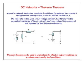
- 1. DC Networks – Thevenin Theorem An active network having two terminals A and B can be replaced by a constant voltage source having an emf, E and an internal resistance, r. The value of E is the open-circuit voltage between A and B and r is the equivalent resistance of the circuit with load removed and the sources of emf replaced by their internal resistances. Thevenin theorem can be used to understand the effect of output resistance on a voltage source under load conditions. E R1 A B R2 rint RTH VTH A B = V
- 2. DC Networks – Thevenin Theorem Use the following procedure to obtain the Thevenin equivalent for the circuit shown, determine the terminal voltage VT and current through the load R3. 1. remove the load resistance from the circuit, 2. determine the open circuit voltage, VTH, across the break, E = 20V R1= 8Ω A B R2 = 4Ω rint = 2Ω VTH A B E = 20V R1= 8Ω R3 = 15Ω R2 = 4Ω rint = 2Ω VT (use the potential divider formula)
- 3. DC Networks – Thevenin Theorem 3. remove each source of emf and replace them with their internal resistances 4. dermine the Thevenin equivalent resistance, RTH ‘looking in’ at the break, 5. replace the load to the Thevenin equivalent circuit and determine the network parameters. A B rint = 2Ω R1= 8Ω R2 = 4Ω RTH B A RTH RLOAD VTH I V
- 4. Activity 1. Use Thevenin theorem to derive the terminal voltage VT and load current. DC Networks – Thevenin Theorem R=20Ω rint = 1Ω E = 48V R2 = 2Ω R1=10Ω VT A B 2. Use Thevenin theorem to derive the terminal voltage VT and load current. RL= 5ΩVB = 24V 3Ω 12Ω V A B 6Ω VT
- 5. Obtain the Thevenin equivalent circuit for the network shown and determine the value of load resistor required for a current of 0.5A to flow between terminals AB. DC Networks – Thevenin Theorem - + R1 = 4Ω B A R2 = 6Ω pd across R1 and R2 = 5 – 2 = 3V - + 1 2 Using the potential divider theorem pd across R2 = 3 x pd across R2 = 3 x 6 4 + 6 R2 R1 + R2 = 1.8V pd across R1 = 3 – 1.8 = 1.2V Determine the voltage across R1 and R2 R1 = 4Ω E1 = 5V E1 = 5V E2 = 2V B A R2 = 6Ω E2 = 2V
- 6. Redraw the circuit indicating the pds and their polarity ( + ve side to highest source). DC Networks – Thevenin Theorem 3 path 1 = 5 – 1.2 = 3.8V path 2 = 2 + 1.8 = 3.8V ETH = 3.8V - + 4Ω B A 6Ω VR1 = 1.2V 5V - + 2V VR2 = 1.8V + + -- The sum of the pd’s must be the same along both paths indicated, tracing each path gives; path 1 path 2 Replace each voltage source with its internal resistance (zero in this case).4 Looking into the circuit from the terminals AB, the 6Ω and 4Ω then appear in parallel. 4 x 6 4 + 6 = 2.4 ΩRTH =
- 7. DC Networks – Thevenin Theorem 4Ω B A 6Ω Replace each voltage source with its internal resistance (zero in this case).4 Looking into the circuit from the terminals AB, the 6Ω and 4Ω then appear in parallel. 4 x 6 4 + 6 = 2.4 ΩRTH = 4 Draw the Thevenin equivalent circuit.5 For a load current IL of 0.5A to flow.6 RTOTAL = ETH IL = 3.8 0.5 = 7.6 Ω RL = RTOTAL – RTH = 7.6 – 2.4 = 5.2Ω - + RTH = 2.4Ω A B ETH 3.8V