More Related Content
More from R G Sanjay Prakash
More from R G Sanjay Prakash (19)
Ch.4
- 1. 4-1
Chapter 4
ENERGY ANALYSIS OF CLOSED SYSTEMS
Moving Boundary Work
4-1C It represents the boundary work for quasi-equilibrium processes.
4-2C Yes.
4-3C The area under the process curve, and thus the boundary work done, is greater in the constant
pressure case.
4-4C 1 kPa ⋅ m 3 = 1 k(N / m 2 ) ⋅ m 3 = 1 kN ⋅ m = 1 kJ
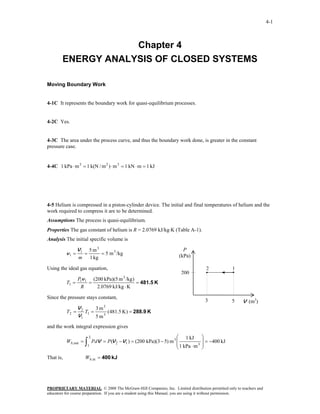
4-5 Helium is compressed in a piston-cylinder device. The initial and final temperatures of helium and the
work required to compress it are to be determined.
Assumptions The process is quasi-equilibrium.
Properties The gas constant of helium is R = 2.0769 kJ/kg⋅K (Table A-1).
Analysis The initial specific volume is
V1 5 m3 P
v1 = = = 5 m 3 /kg (kPa)
m 1 kg
Using the ideal gas equation, 2 1
200
P1v 1 (200 kPa)(5 m 3 /kg )
T1 = = = 481.5 K
R 2.0769 kJ/kg ⋅ K
Since the pressure stays constant,
3 5 V (m3)
V2 3 m3
T2 = T1 = (481.5 K ) = 288.9 K
V1 5 m3
and the work integral expression gives
2 ⎛ 1 kJ ⎞
Wb,out = ∫
1
P dV = P(V 2 −V 1 ) = (200 kPa)(3 − 5) m 3 ⎜
⎜ 1 kPa ⋅ m 3
⎝
⎟ = −400 kJ
⎟
⎠
That is, Wb,in = 400 kJ
PROPRIETARY MATERIAL. © 2008 The McGraw-Hill Companies, Inc. Limited distribution permitted only to teachers and
educators for course preparation. If you are a student using this Manual, you are using it without permission.
- 2. 4-2
4-6 The boundary work done during the process shown in the figure is to be determined.
Assumptions The process is quasi-equilibrium.
P
Analysis No work is done during the process 2-3 since (kPa)
the area under process line is zero. Then the work done is 1
500 3
equal to the area under the process line 1-2: 400
P1 + P2
Wb,out = Area = m(v 2 − v 1 )
2
(100 + 500)kPa ⎛ 1 kJ ⎞ 100 2
= (2 kg)(1.0 − 0.5)m 3 /kg⎜ ⎟
2 ⎜ 1 kPa ⋅ m 3 ⎟
⎝ ⎠
= 300 kJ 0.5 1 v (m3/kg)
4-7E The boundary work done during the process shown in the figure is to be determined.
Assumptions The process is quasi-equilibrium.
P
Analysis The work done is equal to the area under the (psia)
process line 1-2: 2
500
P1 + P2
Wb,out = Area = (V 2 −V 1 )
2
(100 + 500)psia ⎛ 1 Btu ⎞ 1
= (4.0 − 2.0)ft 3 ⎜ ⎟ 100
2 ⎜ 5.404 psia ⋅ ft 3 ⎟
⎝ ⎠
= 111 Btu
2 4 V (ft3)
4-8 A piston-cylinder device contains nitrogen gas at a specified state. The boundary work is to be
determined for the polytropic expansion of nitrogen.
Properties The gas constant for nitrogen is 0.2968 kJ/kg.K (Table A-2).
Analysis The mass and volume of nitrogen at the initial state are
PV1
1 (130 kPa)(0.07 m 3 ) N2
m= = = 0.07802 kg
RT1 (0.2968 kJ/kg.K)(120 + 273 K) 130 kPa
120°C
mRT2 (0.07802 kg)(0.2968 kPa.m 3 /kg.K)(100 + 273 K)
V2 = = = 0.08637 m 3
P2 100 kPa
The polytropic index is determined from
P1V1n = P2V 2n ⎯ (130 kPa)(0.07 m 3 ) n = (100 kPa)(0.08637 m 3 ) n ⎯
⎯→ ⎯→ n = 1.249
The boundary work is determined from
P2V 2 − P1V 1 (100 kPa)(0.08637 m 3 ) − (130 kPa)(0.07 m 3 )
Wb = = = 1.86 kJ
1− n 1 − 1.249
PROPRIETARY MATERIAL. © 2008 The McGraw-Hill Companies, Inc. Limited distribution permitted only to teachers and
educators for course preparation. If you are a student using this Manual, you are using it without permission.
- 3. 4-3
4-9 A piston-cylinder device with a set of stops contains steam at a specified state. Now, the steam is
cooled. The compression work for two cases and the final temperature are to be determined.
Analysis (a) The specific volumes for the initial and final states are (Table A-6)
P = 1 MPa ⎫
1 3 P2 = 1 MPa ⎫ 3
⎬v1 = 0.30661 m /kg ⎬v 2 = 0.23275 m /kg
T1 = 400°C⎭ T2 = 250°C⎭
Noting that pressure is constant during the process, the boundary
Steam
work is determined from
0.3 kg
Wb = mP (v1 − v 2 ) = (0.3 kg)(1000 kPa)(0.30661 − 0.23275)m 3/kg = 22.16 kJ 1 MPa
400°C Q
(b) The volume of the cylinder at the final state is 60% of initial
volume. Then, the boundary work becomes
Wb = mP (v1 − 0.60v1 ) = (0.3 kg)(1000 kPa)(0.30661 − 0.60 × 0.30661)m3/kg = 36.79 kJ
The temperature at the final state is
P2 = 0.5 MPa ⎫
⎪
3 ⎬T2 = 151.8°C (Table A-5)
v 2 = (0.60 × 0.30661) m /kg ⎪
⎭
4-10 A piston-cylinder device contains nitrogen gas at a specified state. The
final temperature and the boundary work are to be determined for the
isentropic expansion of nitrogen.
Properties The properties of nitrogen are R = 0.2968 kJ/kg.K , k = 1.4
(Table A-2a)
N2
Analysis The mass and the final volume of nitrogen are 130 kPa
120°C
P1V1 (130 kPa)(0.07 m 3 )
m= = = 0.07802 kg
RT1 (0.2968 kJ/kg.K)(120 + 273 K)
P1V1k = P2V 2k ⎯ (130 kPa)(0.07 m 3 )1.4 = (100 kPa)V 21.4 ⎯ V 2 = 0.08443 m 3
⎯→ ⎯→
The final temperature and the boundary work are determined as
P2V 2 (100 kPa)(0.08443 m 3 )
T2 = = = 364.6 K
mR (0.07802 kg)(0.2968 kPa.m 3 /kg.K)
P2V 2 − P1V 1 (100 kPa)(0.08443 m 3 ) − (130 kPa)(0.07 m 3 )
Wb = = = 1.64 kJ
1− k 1 − 1.4
PROPRIETARY MATERIAL. © 2008 The McGraw-Hill Companies, Inc. Limited distribution permitted only to teachers and
educators for course preparation. If you are a student using this Manual, you are using it without permission.
- 4. 4-4
4-11 Saturated water vapor in a cylinder is heated at constant pressure until its temperature rises to a
specified value. The boundary work done during this process is to be determined.
Assumptions The process is quasi-equilibrium.
Properties Noting that the pressure remains constant during this process, the specific volumes at the initial
and the final states are (Table A-4 through A-6)
P1 = 300 kPa ⎫ P
3
⎬ v 1 = v g @ 300 kPa = 0.60582 m /kg (kPa
Sat. vapor ⎭
P2 = 300 kPa ⎫ 3 1 2
⎬ v 2 = 0.71643 m /kg 300
T2 = 200°C ⎭
Analysis The boundary work is determined from its definition to be
2 V
Wb,out = ∫
1
P dV = P (V 2 − V1 ) = mP (v 2 − v1 )
⎛ 1 kJ ⎞
= (5 kg)(300 kPa)(0.71643 − 0.60582) m3/kg⎜ ⎟
⎜ 1 kPa ⋅ m3 ⎟
⎝ ⎠
= 165.9 kJ
Discussion The positive sign indicates that work is done by the system (work output).
4-12 Refrigerant-134a in a cylinder is heated at constant pressure until its temperature rises to a specified
value. The boundary work done during this process is to be determined.
Assumptions The process is quasi-equilibrium.
Properties Noting that the pressure remains constant during this process, the specific volumes at the initial
and the final states are (Table A-11 through A-13)
P1 = 900 kPa ⎫ 3
⎬ v 1 = v f @ 900 kPa = 0.0008580 m /kg P
Sat. liquid ⎭ (kPa)
P2 = 900 kPa ⎫ 3
⎬ v 2 = 0.027413 m /kg 1 2
T2 = 70°C ⎭ 900
Analysis The boundary work is determined from its definition to be
V1 0.2 m 3 v
m= = = 233.1 kg
v 1 0.0008580 m 3 /kg
and
2
Wb,out = ∫
1
P dV = P (V 2 − V1 ) = mP(v 2 − v1 )
⎛ 1 kJ ⎞
= (233.1 kg)(900 kPa)(0.027413 − 0.0008580)m3/kg⎜ ⎟
⎜ 1 kPa ⋅ m3 ⎟
⎝ ⎠
= 5571 kJ
Discussion The positive sign indicates that work is done by the system (work output).
PROPRIETARY MATERIAL. © 2008 The McGraw-Hill Companies, Inc. Limited distribution permitted only to teachers and
educators for course preparation. If you are a student using this Manual, you are using it without permission.
- 5. 4-5
4-13 EES Problem 4-12 is reconsidered. The effect of pressure on the work done as the pressure varies
from 400 kPa to 1200 kPa is to be investigated. The work done is to be plotted versus the pressure.
Analysis The problem is solved using EES, and the solution is given below.
"Knowns"
Vol_1L=200 [L]
x_1=0 "saturated liquid state"
P=900 [kPa]
T_2=70 [C]
"Solution"
Vol_1=Vol_1L*convert(L,m^3)
"The work is the boundary work done by the R-134a during the constant pressure process."
W_boundary=P*(Vol_2-Vol_1)
R134a
150
"The mass is:"
125
Vol_1=m*v_1 100
v_1=volume(R134a,P=P,x=x_1)
Vol_2=m*v_2 75
T [°C]
v_2=volume(R134a,P=P,T=T_2) 50 2
1
"Plot information:" 25 900 kPa
v[1]=v_1
0
v[2]=v_2
P[1]=P -25
P[2]=P
-50
T[1]=temperature(R134a,P=P,x=x_1) 10-4 10-3 10-2 10-1
T[2]=T_2 3
v [m /kg]
P Wboundary
[kJ] R134a
[kPa] 105
400 6643
500 6405
600 6183 104
700 5972
P [kPa]
800 5769 2
900 5571 103 1
1000 5377
1100 5187
102
1200 4999
101
10-4 10-3 10-2 10-1
3
v [m /kg]
PROPRIETARY MATERIAL. © 2008 The McGraw-Hill Companies, Inc. Limited distribution permitted only to teachers and
educators for course preparation. If you are a student using this Manual, you are using it without permission.
- 6. 4-6
7250
P = 800 kPa
6800
Wboundary [kJ]
6350
5900
5450
5000
50 60 70 80 90 100 110 120 130
T[2] [C]
7500
T2 = 100 C
7150
Wboundary [kJ]
6800
6450
6100
5750
400 500 600 700 800 900 1000 1100 1200
P [kPa]
7000
6500
Wboundary [kJ]
6000 T2 = 70 C
5500
5000
4500
400 500 600 700 800 900 1000 1100 1200
P [kPa]
PROPRIETARY MATERIAL. © 2008 The McGraw-Hill Companies, Inc. Limited distribution permitted only to teachers and
educators for course preparation. If you are a student using this Manual, you are using it without permission.
- 7. 4-7
4-14E Superheated water vapor in a cylinder is cooled at constant pressure until 70% of it condenses. The
boundary work done during this process is to be determined.
Assumptions The process is quasi-equilibrium.
Properties Noting that the pressure remains constant during this process, the specific volumes at the initial
and the final states are (Table A-4E through A-6E)
P1 = 40 psia ⎫ 3 P
⎬v 1 = 15.686 ft /lbm (psia)
T1 = 600°F ⎭
P2 = 40 psia ⎫
⎬ v 2 = v f + x 2v fg 2 1
x 2 = 0.3 ⎭ 40
= 0.01715 + 0.3(10.501 − 0.01715)
= 3.1623 ft 3 /lbm
v
Analysis The boundary work is determined from its definition to be
2
Wb,out = ∫
1
P dV = P(V 2 − V1 ) = mP(v 2 − v1 )
⎛ 1 Btu ⎞
= (16 lbm)(40 psia)(3.1623 − 15.686)ft 3/lbm⎜ ⎟
⎜ 5.4039 psia ⋅ ft 3 ⎟
⎝ ⎠
= −1483 Btu
Discussion The negative sign indicates that work is done on the system (work input).
4-15 Air in a cylinder is compressed at constant temperature until its pressure rises to a specified value.
The boundary work done during this process is to be determined.
Assumptions 1 The process is quasi-equilibrium. 2 Air is an ideal gas.
Properties The gas constant of air is R = 0.287 kJ/kg.K (Table A-1). P
Analysis The boundary work is determined from its definition to be
2
2 V2 P T = 12°C
Wb,out = ∫
1
P dV = PV1 ln
1
V1
= mRT ln 1
P2 1
150 kPa
= (2.4 kg)(0.287 kJ/kg ⋅ K)(285 K)ln V
600 kPa
= −272 kJ
Discussion The negative sign indicates that work is done on the system (work input).
PROPRIETARY MATERIAL. © 2008 The McGraw-Hill Companies, Inc. Limited distribution permitted only to teachers and
educators for course preparation. If you are a student using this Manual, you are using it without permission.
- 8. 4-8
4-16E A gas in a cylinder is heated and is allowed to expand to a specified pressure in a process during
which the pressure changes linearly with volume. The boundary work done during this process is to be
determined.
Assumptions The process is quasi-equilibrium.
Analysis (a) The pressure of the gas changes linearly with volume, and thus the process curve on a P-V
diagram will be a straight line. The boundary work during this process is simply the area under the process
curve, which is a trapezoidal. Thus,
At state 1:
P
P1 = aV1 + b (psia)
15 psia = (5 psia/ft 3 )(7 ft 3 ) + b P = aV + b
100 2
b = −20 psia
At state 2: 1
15
P2 = aV 2 + b
100 psia = (5 psia/ft 3 )V 2 + (−20 psia) V
3 7 (ft3)
V 2 = 24 ft
and,
P1 + P2 (100 + 15)psia ⎛ 1 Btu ⎞
Wb,out = Area = (V 2 −V1 ) = (24 − 7)ft 3 ⎜ ⎟
2 2 ⎜ 5.4039 psia ⋅ ft 3 ⎟
⎝ ⎠
= 181 Btu
Discussion The positive sign indicates that work is done by the system (work output).
4-17 [Also solved by EES on enclosed CD] A gas in a cylinder expands polytropically to a specified
volume. The boundary work done during this process is to be determined.
Assumptions The process is quasi-equilibrium.
Analysis The boundary work for this polytropic process can be determined directly from
n 1.3
⎛V ⎞ ⎛ 0.03 m 3 ⎞
P2 = P1 ⎜ 1
⎜V ⎟ = (150 kPa)⎜
⎟
⎟ = 12.74 kPa P
⎜ 0.2 m 3 ⎟
⎝ 2 ⎠ ⎝ ⎠ (kPa)
1
and, 15
2 P2V 2 − P1V1
Wb,out = ∫1
P dV =
1− n
PV
2
(12.74 × 0.2 − 150 × 0.03) kPa ⋅ m 3 ⎛ 1 kJ ⎞
= ⎜ ⎟
1 − 1.3 ⎜ 1 kPa ⋅ m 3 ⎟ V
⎝ ⎠
0.0 0.2 (m3)
= 6.51 kJ
Discussion The positive sign indicates that work is done by the system (work output).
PROPRIETARY MATERIAL. © 2008 The McGraw-Hill Companies, Inc. Limited distribution permitted only to teachers and
educators for course preparation. If you are a student using this Manual, you are using it without permission.
- 9. 4-9
4-18 EES Problem 4-17 is reconsidered. The process described in the problem is to be plotted on a P-V
diagram, and the effect of the polytropic exponent n on the boundary work as the polytropic exponent
varies from 1.1 to 1.6 is to be plotted.
Analysis The problem is solved using EES, and the solution is given below.
Function BoundWork(P[1],V[1],P[2],V[2],n)
"This function returns the Boundary Work for the polytropic process. This function is required
since the expression for boundary work depens on whether n=1 or n<>1"
If n<>1 then
BoundWork:=(P[2]*V[2]-P[1]*V[1])/(1-n)"Use Equation 3-22 when n=1"
else
BoundWork:= P[1]*V[1]*ln(V[2]/V[1]) "Use Equation 3-20 when n=1"
endif
end
"Inputs from the diagram window"
{n=1.3
P[1] = 150 [kPa]
V[1] = 0.03 [m^3]
V[2] = 0.2 [m^3]
Gas$='AIR'}
"System: The gas enclosed in the piston-cylinder device."
"Process: Polytropic expansion or compression, P*V^n = C"
P[2]*V[2]^n=P[1]*V[1]^n
"n = 1.3" "Polytropic exponent"
"Input Data"
W_b = BoundWork(P[1],V[1],P[2],V[2],n)"[kJ]"
"If we modify this problem and specify the mass, then we can calculate the final temperature of
the fluid for compression or expansion"
m[1] = m[2] "Conservation of mass for the closed system"
"Let's solve the problem for m[1] = 0.05 kg"
m[1] = 0.05 [kg]
"Find the temperatures from the pressure and specific volume."
T[1]=temperature(gas$,P=P[1],v=V[1]/m[1])
T[2]=temperature(gas$,P=P[2],v=V[2]/m[2])
PROPRIETARY MATERIAL. © 2008 The McGraw-Hill Companies, Inc. Limited distribution permitted only to teachers and
educators for course preparation. If you are a student using this Manual, you are using it without permission.
- 10. 4-10
160
140
120
100
P [kPa]
80
60
40
20
0
0.02 0.04 0.06 0.08 0.1 0.12 0.14 0.16 0.18 0.2
3
V [m ]
8
n Wb [kJ]
1.1 7.776
1.156 7.393 7.5
1.211 7.035
1.267 6.7
7
1.322 6.387
Wb [kJ]
1.378 6.094
1.433 5.82 6.5
1.489 5.564
1.544 5.323
6
1.6 5.097
5.5
5
1.1 1.2 1.3 1.4 1.5 1.6
n
PROPRIETARY MATERIAL. © 2008 The McGraw-Hill Companies, Inc. Limited distribution permitted only to teachers and
educators for course preparation. If you are a student using this Manual, you are using it without permission.
- 11. 4-11
4-19 Nitrogen gas in a cylinder is compressed polytropically until the temperature rises to a specified
value. The boundary work done during this process is to be determined.
Assumptions 1 The process is quasi-equilibrium. 2 Nitrogen is an ideal gas.
Properties The gas constant for nitrogen is R = 0.2968 kJ/kg.K (Table A-2a)
Analysis The boundary work for this polytropic process can be
determined from
P
2 P V − PV mR(T2 − T1 )
Wb,out = ∫1
P dV = 2 2 1 1 =
1− n 1− n
2
(2 kg)(0.2968 kJ/kg ⋅ K)(360 − 300)K PV n =C
=
1 − 1.4
= −89.0 kJ
1
Discussion The negative sign indicates that work is done on
V
the system (work input).
4-20 [Also solved by EES on enclosed CD] A gas whose equation of state is v ( P + 10 / v 2 ) = Ru T expands
in a cylinder isothermally to a specified volume. The unit of the quantity 10 and the boundary work done
during this process are to be determined.
Assumptions The process is quasi-equilibrium.
P
2
Analysis (a) The term 10 / v must have pressure units
since it is added to P.
Thus the quantity 10 must have the unit kPa·m6/kmol2.
(b) The boundary work for this process can be determined from T = 300 K
Ru T 10 Ru T 10 NRu T 10 N 2
P= − = − = −
v v 2 V / N (V / N ) 2 V V2 V
2 4
and
2⎛
2⎞
⎛ ⎞
⎜ NRuT − 10 N ⎟dV = NRuT ln V 2 + 10 N 2 ⎜ 1 − 1 ⎟
2
Wb,out =
1 ∫ P dV =
1 ⎜ V
⎝
∫ 2 ⎟
V ⎠ V1 ⎜V V ⎟
⎝ 2 1⎠
3
4m
= (0.5 kmol)(8.314 kJ/kmol ⋅ K)(300 K)ln
2 m3
⎛ 1 1 ⎞⎛ 1 kJ ⎞
+ (10 kPa ⋅ m 6 /kmol2 )(0.5kmol)2 ⎜ ⎟⎜ ⎟
⎜ 4 m3 − 2 m3 ⎟⎜ 1 kPa ⋅ m3 ⎟
= 864 kJ ⎝ ⎠⎝ ⎠
Discussion The positive sign indicates that work is done by the system (work output).
PROPRIETARY MATERIAL. © 2008 The McGraw-Hill Companies, Inc. Limited distribution permitted only to teachers and
educators for course preparation. If you are a student using this Manual, you are using it without permission.
- 12. 4-12
4-21 EES Problem 4-20 is reconsidered. Using the integration feature, the work done is to be calculated
and compared, and the process is to be plotted on a P-V diagram.
Analysis The problem is solved using EES, and the solution is given below.
"Input Data"
N=0.5 [kmol]
v1_bar=2/N "[m^3/kmol]"
v2_bar=4/N "[m^3/kmol]"
T=300 [K]
R_u=8.314 [kJ/kmol-K]
"The quation of state is:"
v_bar*(P+10/v_bar^2)=R_u*T "P is in kPa"
"using the EES integral function, the boundary work, W_bEES, is"
W_b_EES=N*integral(P,v_bar, v1_bar, v2_bar,0.01)
"We can show that W_bhand= integeral of Pdv_bar is
(one should solve for P=F(v_bar) and do the integral 'by hand' for practice)."
W_b_hand = N*(R_u*T*ln(v2_bar/v1_bar) +10*(1/v2_bar-1/v1_bar))
"To plot P vs v_bar, define P_plot =f(v_bar_plot, T) as"
{v_bar_plot*(P_plot+10/v_bar_plot^2)=R_u*T}
" P=P_plot and v_bar=v_bar_plot just to generate the parametric table for plotting purposes. To
plot P vs v_bar for a new temperature or v_bar_plot range, remove the '{' and '}' from the above
equation, and reset the v_bar_plot values in the Parametric Table. Then press F3 or select Solve
Table from the Calculate menu. Next select New Plot Window under the Plot menu to plot the
new data."
P vs v bar
Pplot vplot 650
622.9 4 600 1
560.7 4.444 550
509.8 4.889 500
467.3 5.333 T = 300 K
450
431.4 5.778
P plot [kPa]
400
400.6 6.222 350
373.9 6.667 300 2
350.5 7.111
250
329.9 7.556 Area = W boundary
200
311.6 8
150
100
50
0
3.5 4.0 4.5 5.0 5.5 6.0 6.5 7.0 7.5 8.0 8.5
v [m ^3/km ol]
plot
PROPRIETARY MATERIAL. © 2008 The McGraw-Hill Companies, Inc. Limited distribution permitted only to teachers and
educators for course preparation. If you are a student using this Manual, you are using it without permission.
- 13. 4-13
4-22 CO2 gas in a cylinder is compressed until the volume drops to a specified value. The pressure changes
during the process with volume as P = aV −2 . The boundary work done during this process is to be
determined.
Assumptions The process is quasi-equilibrium.
P
Analysis The boundary work done during this
process is determined from 2
2 2⎛ a ⎞ ⎛ 1 1 ⎞ P = aV--2
Wb,out = ∫ PdV = ∫
1 1
⎜ 2 ⎟dV = − a⎜
⎝V ⎠
⎜V − V ⎟
⎝ 2
⎟
1 ⎠
1
⎛ 1 1 ⎞⎛ 1 kJ ⎞
= −(8 kPa ⋅ m 6 )⎜ − ⎟⎜ ⎟
⎜ 0.1 m 3 0.3 m 3 ⎟⎜ 1 kPa ⋅ m 3 ⎟ V
⎝ ⎠⎝ ⎠
0.1 0.3 (m3)
= −53.3 kJ
Discussion The negative sign indicates that work is done on the system (work input).
4-23 Several sets of pressure and volume data are taken as a gas expands. The boundary work done
during this process is to be determined using the experimental data.
Assumptions The process is quasi-equilibrium.
Analysis Plotting the given data on a P-V diagram on a graph paper and evaluating the area under the
process curve, the work done is determined to be 0.25 kJ.
4-24 A piston-cylinder device contains nitrogen gas at a specified state. The boundary work is to be
determined for the isothermal expansion of nitrogen.
Properties The properties of nitrogen are R = 0.2968 kJ/kg.K , k = 1.4 (Table A-2a).
Analysis We first determine initial and final volumes from ideal gas relation, and find the boundary work
using the relation for isothermal expansion of an ideal gas
mRT (0.25 kg)(0.2968 kJ/kg.K)(120 + 273 K)
V1 = = = 0.2243 m 3
P1 (130 kPa)
mRT (0.25 kg)(0.2968 kJ/kg.K)(120 + 273 K) N2
V2 = = = 0.2916 m 3
P2 (100 kPa) 130 kPa
120°C
⎛V ⎞ ⎛ 0.2916 m 3 ⎞
Wb = P1V1 ln⎜ 2
⎜V ⎟ = (130 kPa)(0.2243 m 3 ) ln⎜
⎟
⎟ = 7.65 kJ
⎜ 0.2243 m 3 ⎟
⎝ 1 ⎠ ⎝ ⎠
PROPRIETARY MATERIAL. © 2008 The McGraw-Hill Companies, Inc. Limited distribution permitted only to teachers and
educators for course preparation. If you are a student using this Manual, you are using it without permission.
- 14. 4-14
4-25 A piston-cylinder device contains air gas at a specified state. The air undergoes a cycle with three
processes. The boundary work for each process and the net work of the cycle are to be determined.
Properties The properties of air are R = 0.287 kJ/kg.K , k = 1.4 (Table A-2a).
Analysis For the isothermal expansion process:
mRT (0.15 kg)(0.287 kJ/kg.K)(350 + 273 K)
V1 = = = 0.01341 m 3
P1 (2000 kPa)
Air
mRT (0.15 kg)(0.287 kJ/kg.K)(350 + 273 K) 2 MPa
V2 = = = 0.05364 m 3 350°C
P2 (500 kPa)
⎛V ⎞ ⎛ 0.05364 m3 ⎞
Wb,1− 2 = PV1 ln⎜ 2 ⎟ = (2000 kPa)(0.01341 m3 ) ln⎜
⎜V ⎟
⎟ = 37.18 kJ
1 ⎜ 0.01341 m3 ⎟
⎝ 1⎠ ⎝ ⎠
For the polytropic compression process:
P2V 2n = P3V 3n ⎯ (500 kPa)(0.05364 m 3 )1.2 = (2000 kPa)V 31.2 ⎯ V 3 = 0.01690 m 3
⎯→ ⎯→
P3V 3 − P2V 2 (2000 kPa)(0.01690 m 3 ) − (500 kPa)(0.05364 m 3 )
Wb , 2 − 3 = = = -34.86 kJ
1− n 1 − 1.2
For the constant pressure compression process:
Wb,3−1 = P3 (V 1 −V 3 ) = (2000 kPa)(0.01341 − 0.01690)m 3 = -6.97 kJ
The net work for the cycle is the sum of the works for each process
Wnet = Wb,1− 2 + Wb,2−3 + Wb,3−1 = 37.18 + (−34.86) + (−6.97) = -4.65 kJ
PROPRIETARY MATERIAL. © 2008 The McGraw-Hill Companies, Inc. Limited distribution permitted only to teachers and
educators for course preparation. If you are a student using this Manual, you are using it without permission.
- 15. 4-15
4-26 A saturated water mixture contained in a spring-loaded piston-cylinder device is heated until the
pressure and temperature rises to specified values. The work done during this process is to be determined.
Assumptions The process is quasi-equilibrium.
Analysis The initial state is saturated mixture at 90°C. The
pressure and the specific volume at this state are (Table A-4), P
2
P1 = 70.183 kPa 800 kPa
v 1 = v f + xv fg
= 0.001036 + (0.10)(2.3593 − 0.001036) 1
3
= 0.23686 m /kg
The final specific volume at 800 kPa and 250°C is (Table A-6) v
v 2 = 0.29321 m 3 /kg
Since this is a linear process, the work done is equal to the area under the process line 1-2:
P1 + P2
Wb,out = Area = m(v 2 − v 1 )
2
(70.183 + 800)kPa ⎛ 1 kJ ⎞
= (1 kg)(0.29321 − 0.23686)m 3 ⎜ ⎟
2 ⎝ 1 kPa ⋅ m 3 ⎠
= 24.52 kJ
4-27 A saturated water mixture contained in a spring-loaded piston-cylinder device is cooled until it is
saturated liquid at a specified temperature. The work done during this process is to be determined.
Assumptions The process is quasi-equilibrium.
Analysis The initial state is saturated mixture at 1 MPa. The
specific volume at this state is (Table A-5), P
v 1 = v f + xv fg
= 0.001127 + (0.10)(0.19436 − 0.001127) 1 MPa 1
3
= 0.020450 m /kg
2
The final state is saturated liquid at 100°C (Table A-4)
v
P2 = 101.42 kPa
v 2 = v f = 0.001043 m 3 /kg
Since this is a linear process, the work done is equal to the area under the process line 1-2:
P1 + P2
Wb,out = Area = m(v 2 − v 1 )
2
(1000 + 101.42)kPa ⎛ 1 kJ ⎞
= (0.5 kg)(0.001043 − 0.020450)m 3 ⎜ ⎟
2 ⎝ 1 kPa ⋅ m 3 ⎠
= −5.34 kJ
The negative sign shows that the work is done on the system in the amount of 5.34 kJ.
PROPRIETARY MATERIAL. © 2008 The McGraw-Hill Companies, Inc. Limited distribution permitted only to teachers and
educators for course preparation. If you are a student using this Manual, you are using it without permission.
- 16. 4-16
4-28 Argon is compressed in a polytropic process. The final temperature is to be determined.
Assumptions The process is quasi-equilibrium.
Analysis For a polytropic expansion or compression process,
Pv n = Constant
For an ideal gas,
Pv = RT
Combining these equations produces
( n-1 )/n 0.2 / 1.2
⎛P ⎞ ⎛ 1200 kPa ⎞
⎜
T2 = T1 ⎜ 2 ⎟
⎟ = (303 K)⎜ ⎟ = 444.7 K
⎝ P1 ⎠ ⎝ 120 kPa ⎠
PROPRIETARY MATERIAL. © 2008 The McGraw-Hill Companies, Inc. Limited distribution permitted only to teachers and
educators for course preparation. If you are a student using this Manual, you are using it without permission.
- 17. 4-17
Closed System Energy Analysis
4-29 Saturated water vapor is isothermally condensed to a saturated liquid in a piston-cylinder device. The
heat transfer and the work done are to be determined.
Assumptions 1 The cylinder is stationary and thus the kinetic and potential energy changes are zero. 2
There are no work interactions involved other than the boundary work. 3 The thermal energy stored in the
cylinder itself is negligible. 4 The compression or expansion process is quasi-equilibrium.
Analysis We take the contents of the cylinder as the system. This is a closed system since no mass enters
or leaves. The energy balance for this stationary closed system can be expressed as
E in − E out = ΔE system
1 24
4 3 1 24
4 3
Net energy transfer Change in internal, kinetic,
by heat, work, and mass potential, etc. energies
Water
Wb,in − Qout = ΔU = m(u 2 − u1 ) (since KE = PE = 0)
200°C Heat
Qout = Wb,in − m(u 2 − u1 ) sat. vapor
The properties at the initial and final states are (Table A-4)
T1 = 200°C ⎫ v 1 = v g = 0.12721 m 3 / kg T
⎬
x1 = 1 ⎭ u1 = u g = 2594.2 kJ/kg
P1 = P2 = 1554.9 kPa
2 1
T2 = 200°C ⎫ v 2 = v f = 0.001157 m 3 / kg
⎬
x2 = 0 ⎭ u 2 = u f = 850.46 kJ/kg
v
The work done during this process is
2 ⎛ 1 kJ ⎞
wb,out = ∫1
P dV = P (v 2 − v 1 ) = (1554.9 kPa)(0.001157 − 0.12721) m 3 /kg⎜
⎜ 1 kPa ⋅ m 3
⎝
⎟ = −196.0 kJ/kg
⎟
⎠
That is,
wb,in = 196.0 kJ/kg
Substituting the energy balance equation, we get
q out = wb,in − (u 2 − u1 ) = wb,in + u fg = 196.0 + 1743.7 = 1940 kJ/kg
PROPRIETARY MATERIAL. © 2008 The McGraw-Hill Companies, Inc. Limited distribution permitted only to teachers and
educators for course preparation. If you are a student using this Manual, you are using it without permission.
- 18. 4-18
4-30E The heat transfer during a process that a closed system undergoes without any internal energy
change is to be determined.
Assumptions 1 The system is stationary and thus the kinetic and potential energy changes are zero. 2 The
compression or expansion process is quasi-equilibrium.
Analysis The energy balance for this stationary closed system can be expressed as
E in − E out = ΔE system
1 24
4 3 1 24
4 3
Net energy transfer Change in internal, kinetic,
by heat, work, and mass potential, etc. energies
Qin − Wout = ΔU = 0 (since KE = PE = 0)
Qin = Wout
Then,
⎛ 1 Btu ⎞
Qin = 1.6 × 10 6 lbf ⋅ ft ⎜ ⎟ = 2056 Btu
⎝ 778.17 lbf ⋅ ft ⎠
4-31 The table is to be completed using conservation of energy principle for a closed system.
Analysis The energy balance for a closed system can be expressed as
E in − E out = ΔE system
1 24
4 3 1 24
4 3
Net energy transfer Change in internal, kinetic,
by heat, work, and mass potential, etc. energies
Qin − Wout = E 2 − E1 = m(e 2 − e1 )
Application of this equation gives the following completed table:
Qin Wout E1 E2 m e2 − e1
(kJ) (kJ) (kJ) (kJ) (kg) (kJ/kg)
280 440 1020 860 3 -53.3
-350 130 550 70 5 -96
-40 260 300 0 2 -150
300 550 750 500 1 -250
-400 -200 500 300 2 -100
PROPRIETARY MATERIAL. © 2008 The McGraw-Hill Companies, Inc. Limited distribution permitted only to teachers and
educators for course preparation. If you are a student using this Manual, you are using it without permission.
- 19. 4-19
4-32 A substance is contained in a well-insulated, rigid container that is equipped with a stirring device.
The change in the internal energy of this substance for a given work input is to be determined.
Assumptions 1 The tank is stationary and thus the kinetic and potential energy changes are zero. 2 The
tank is insulated and thus heat transfer is negligible.
Analysis This is a closed system since no mass enters or
leaves. The energy balance for this stationary closed system
can be expressed as
E in − E out = ΔE system
1 24
4 3 1 24
4 3
Net energy transfer Change in internal, kinetic,
by heat, work, and mass potential, etc. energies
Wsh,in = ΔU (since KE = PE = 0)
Then,
ΔU = 15 kJ
4-33 Motor oil is contained in a rigid container that is equipped with a stirring device. The rate of specific
energy increase is to be determined.
Analysis This is a closed system since no mass enters or leaves. The energy balance for closed system can
be expressed as
E in − E out = ΔE system
1 24
4 3 1 24
4 3
Net energy transfer Change in internal, kinetic,
by heat, work, and mass potential, etc. energies
& & &
Qin + Wsh,in = ΔE
Then,
& & &
ΔE = Qin + Wsh,in = 1 + 1.5 = 2.5 = 2.5 W
Dividing this by the mass in the system gives
&
ΔE 2.5 J/s
Δe =
& = = 1.67 J/kg ⋅ s
m 1.5 kg
PROPRIETARY MATERIAL. © 2008 The McGraw-Hill Companies, Inc. Limited distribution permitted only to teachers and
educators for course preparation. If you are a student using this Manual, you are using it without permission.
- 20. 4-20
4-34E R-134a contained in a rigid vessel is heated. The heat transfer is to be determined.
Assumptions 1 The system is stationary and thus the kinetic and potential energy changes are zero. 2 There
are no work interactions involved 3 The thermal energy stored in the vessel itself is negligible.
Analysis We take R-134a as the system. This is a closed system since no
mass enters or leaves. The energy balance for this stationary closed system
can be expressed as
R-134a Q
E in − E out = ΔE system 1 ft3
1 24
4 3 1 24
4 3
Net energy transfer
by heat, work, and mass
Change in internal, kinetic,
potential, etc. energies −20°F
Qin = ΔU = m(u 2 − u1 ) (since KE = PE = 0) x = 0.277
The properties at the initial and final states are (Tables A-11E, A-13E)
T1 = −20°F ⎫ v 1 = v f + xv fg = 0.01156 + (0.277)(3.4426 − 0.01156) = 0.96196 ft 3 / lbm
⎬
x1 = 0.277 ⎭ u1 = u f + xu fg = 6.019 + (0.277)(85.874) = 29.81 Btu/lbm
T2 = 100°F ⎫
⎪
⎬ u 2 = 111.30 Btu/lbm
3 T
v 2 = v 1 = 0.96196 ft / lbm ⎪
⎭
Note that the final state is superheated vapor and the internal energy at 2
this state should be obtained by interpolation using 50 psia and 60 psia
mini tables (100°F line) in Table A-13E. The mass in the system is
V1 1 ft 3 1
m= = = 1.0395 lbm
v 1 0.96196 ft 3 /lbm v
Substituting,
Qin = m(u 2 − u1 ) = (1.0395 lbm)(111.30 − 29.81) Btu/lbm = 84.7 Btu
PROPRIETARY MATERIAL. © 2008 The McGraw-Hill Companies, Inc. Limited distribution permitted only to teachers and
educators for course preparation. If you are a student using this Manual, you are using it without permission.
- 21. 4-21
4-35 An insulated rigid tank is initially filled with a saturated liquid-vapor mixture of water. An electric
heater in the tank is turned on, and the entire liquid in the tank is vaporized. The length of time the heater
was kept on is to be determined, and the process is to be shown on a P-v diagram.
Assumptions 1 The tank is stationary and thus the kinetic and potential energy changes are zero. 2 The
device is well-insulated and thus heat transfer is negligible. 3 The energy stored in the resistance wires, and
the heat transferred to the tank itself is negligible.
Analysis We take the contents of the tank as the system. This is a closed system since no mass enters or
leaves. Noting that the volume of the system is constant and thus there is no boundary work, the energy
balance for this stationary closed system can be expressed as
Ein − Eout = ΔEsystem
1 24
4 3 123
4 4
Net energy transfer Change in internal, kinetic, H2O
by heat, work, and mass potential, etc. energies V = const.
We,in = ΔU = m(u2 − u1 ) (since Q = KE = PE = 0)
VIΔt = m(u2 − u1 )
We
The properties of water are (Tables A-4 through A-6)
P = 100kPa ⎫ v f = 0.001043, v g = 1.6941 m3 /kg
1
⎬
x1 = 0.25 ⎭ u f = 417.40, u fg = 2088.2 kJ/kg
T
v1 = v f + x1v fg = 0.001043 + [0.25 × (1.6941 − 0.001043)] = 0.42431 m3/kg 2
u1 = u f + x1u fg = 417.40 + (0.25 × 2088.2 ) = 939.4 kJ/kg
⎫
v 2 = v1 = 0.42431 m3/kg ⎪ 1
⎬ u2 = u g @ 0.42431m 3 /kg = 2556.2 kJ/kg v
sat.vapor ⎪
⎭
Substituting,
⎛ 1000 VA ⎞
(110 V)(8 A)Δt = (5 kg)(2556.2 − 939.4)kJ/kg⎜
⎜ 1 kJ/s ⎟⎟
⎝ ⎠
Δt = 9186 s ≅ 153.1 min
PROPRIETARY MATERIAL. © 2008 The McGraw-Hill Companies, Inc. Limited distribution permitted only to teachers and
educators for course preparation. If you are a student using this Manual, you are using it without permission.
- 22. 4-22
4-36 EES Problem 4-35 is reconsidered. The effect of the initial mass of water on the length of time
required to completely vaporize the liquid as the initial mass varies from 1 kg to 10 kg is to be investigated.
The vaporization time is to be plotted against the initial mass.
Analysis The problem is solved using EES, and the solution is given below.
PROCEDURE P2X2(v[1]:P[2],x[2])
Fluid$='Steam_IAPWS'
If v[1] > V_CRIT(Fluid$) then
P[2]=pressure(Fluid$,v=v[1],x=1)
x[2]=1
else
P[2]=pressure(Fluid$,v=v[1],x=0)
x[2]=0
EndIf
End
"Knowns"
{m=5 [kg]}
P[1]=100 [kPa]
y=0.75 "moisture"
Volts=110 [V]
I=8 [amp]
"Solution"
"Conservation of Energy for the closed tank:"
E_dot_in-E_dot_out=DELTAE_dot
E_dot_in=W_dot_ele "[kW]"
W_dot_ele=Volts*I*CONVERT(J/s,kW) "[kW]"
E_dot_out=0 "[kW]"
DELTAE_dot=m*(u[2]-u[1])/DELTAt_s "[kW]"
DELTAt_min=DELTAt_s*convert(s,min) "[min]"
"The quality at state 1 is:"
Fluid$='Steam_IAPWS'
x[1]=1-y
u[1]=INTENERGY(Fluid$,P=P[1], x=x[1]) "[kJ/kg]"
v[1]=volume(Fluid$,P=P[1], x=x[1]) "[m^3/kg]"
T[1]=temperature(Fluid$,P=P[1], x=x[1]) "[C]"
"Check to see if state 2 is on the saturated liquid line or saturated vapor line:"
Call P2X2(v[1]:P[2],x[2])
u[2]=INTENERGY(Fluid$,P=P[2], x=x[2]) "[kJ/kg]"
v[2]=volume(Fluid$,P=P[2], x=x[2]) "[m^3/kg]"
T[2]=temperature(Fluid$,P=P[2], x=x[2]) "[C]"
PROPRIETARY MATERIAL. © 2008 The McGraw-Hill Companies, Inc. Limited distribution permitted only to teachers and
educators for course preparation. If you are a student using this Manual, you are using it without permission.
- 23. 4-23
S te a m
700
600
500
400
T [°C]
300
200
2
43 7.9 kP a
100 10 0 kP a
1
0.0 5 0.1 0 .2 0 .5
0
1 0 -3 1 0 -2 1 0 -1 100 101 102 103
3
v [m /k g ]
Δtmin m
[min] [kg]
30.63 1
61.26 2
91.89 3
122.5 4
153.2 5
183.8 6
214.4 7
245 8
275.7 9
306.3 10
350
300
250
200
Δ t m in [m in]
150
100
50
0
1 2 3 4 5 6 7 8 9 10
m [kg]
PROPRIETARY MATERIAL. © 2008 The McGraw-Hill Companies, Inc. Limited distribution permitted only to teachers and
educators for course preparation. If you are a student using this Manual, you are using it without permission.
- 24. 4-24
4-37 A cylinder is initially filled with R-134a at a specified state. The refrigerant is cooled at constant
pressure. The amount of heat loss is to be determined, and the process is to be shown on a T-v
diagram.
Assumptions 1 The cylinder is stationary and thus the kinetic and potential energy changes are zero. 2
There are no work interactions involved other than the boundary work. 3 The thermal energy stored in the
cylinder itself is negligible. 4 The compression or expansion process is quasi-equilibrium.
Analysis We take the contents of the cylinder as the system. This is a closed system since no mass enters
or leaves. The energy balance for this stationary closed system can be expressed as
Ein − Eout = ΔEsystem
1 24
4 3 123
4 4
Net energy transfer Change in internal, kinetic,
by heat, work, and mass potential, etc. energies
− Qout − Wb,out = ΔU = m(u2 − u1 ) (since KE = PE = 0)
− Qout = m(h2 − h1 ) Q
R-134a
since ΔU + Wb = ΔH during a constant pressure quasi- 800 kPa
equilibrium process. The properties of R-134a are
(Tables A-11 through A-13)
T
P1 = 800 kPa ⎫ 1
⎬ h1 = 306.88 kJ/kg
T1 = 70°C ⎭
P2 = 800 kPa ⎫ 2
⎬ h2 = h f @15°C = 72.34 kJ/kg
T2 = 15°C ⎭
Substituting,
v
Qout = - (5 kg)(72.34 - 306.88) kJ/kg = 1173 kJ
PROPRIETARY MATERIAL. © 2008 The McGraw-Hill Companies, Inc. Limited distribution permitted only to teachers and
educators for course preparation. If you are a student using this Manual, you are using it without permission.
- 25. 4-25
4-38E A cylinder contains water initially at a specified state. The water is heated at constant pressure. The
final temperature of the water is to be determined, and the process is to be shown on a T-v diagram.
Assumptions 1 The cylinder is stationary and thus the kinetic and potential energy changes are zero. 2 The
thermal energy stored in the cylinder itself is negligible. 3 The compression or expansion process is quasi-
equilibrium.
Analysis We take the contents of the cylinder as the system. This is a closed system since no mass enters
or leaves. The energy balance for this stationary closed system can be expressed as
E in − E out = ΔE system
1 24
4 3 1 24
4 3
Net energy transfer Change in internal, kinetic,
by heat, work, and mass potential, etc. energies
Qin − Wb,out = ΔU = m(u 2 − u1 ) (since KE = PE = 0)
Q
Qin = m(h2 − h1 ) H2O
120 psia
since ΔU + Wb = ΔH during a constant pressure quasi-equilibrium
process. The properties of water are (Tables A-6E)
V1 2 ft 3
v1 = = = 4 ft 3 /lbm T
m 0.5 lbm 2
P1 = 120 psia ⎫ ⎪ 1
3 ⎬ h1 = 1217.0 Btu/lbm
v 1 = 4 ft /lbm ⎪
⎭
Substituting,
200 Btu = (0.5 lbm)(h2 − 1217.0)Btu/lbm v
h2 = 1617.0 Btu/lbm
Then,
P2 = 120 psia ⎫
⎬ T2 = 1161.4°F
h2 = 1617.0 Btu/lbm ⎭
PROPRIETARY MATERIAL. © 2008 The McGraw-Hill Companies, Inc. Limited distribution permitted only to teachers and
educators for course preparation. If you are a student using this Manual, you are using it without permission.
- 26. 4-26
4-39 A cylinder is initially filled with saturated liquid water at a specified pressure. The water is heated
electrically as it is stirred by a paddle-wheel at constant pressure. The voltage of the current source is to be
determined, and the process is to be shown on a P-v diagram.
Assumptions 1 The cylinder is stationary and thus the kinetic and potential energy changes are zero. 2 The
cylinder is well-insulated and thus heat transfer is negligible. 3 The thermal energy stored in the cylinder
itself is negligible. 4 The compression or expansion process is quasi-equilibrium.
Analysis We take the contents of the cylinder as the system. This is a closed system since no mass enters
or leaves. The energy balance for this stationary closed system can be expressed as
E in − E out = ΔE system
1 24
4 3 1 24
4 3
Net energy transfer Change in internal, kinetic,
by heat, work, and mass potential, etc. energies
We,in + W pw,in − W b,out = ΔU (since Q = KE = PE = 0)
H2O
We,in + W pw,in = m(h2 − h1 )
P = const.
( VIΔt ) + W pw,in = m(h2 − h1 )
Wpw
We
since ΔU + Wb = ΔH during a constant pressure quasi-equilibrium
process. The properties of water are (Tables A-4 through A-6)
P = 175 kPa ⎫ h1 = h f @175 kPa = 487.01 kJ/kg
1
⎬ 3
sat.liquid ⎭ v1 = v f @175 kPa = 0.001057 m /kg
P2 = 175 kPa ⎫
⎬ h2 = h f + x2 h fg = 487.01 + (0.5 × 2213.1) = 1593.6 kJ/kg
x2 = 0.5 ⎭
V1 0.005 m3
m= = = 4.731 kg P
v1 0.001057 m3/kg
Substituting,
VIΔt + (400kJ) = (4.731 kg)(1593.6 − 487.01)kJ/kg 1 2
VIΔt = 4835 kJ
4835 kJ ⎛ 1000 VA ⎞
V= ⎜ ⎟ = 223.9 V v
(8 A)(45 × 60 s) ⎜ 1 kJ/s ⎟
⎝ ⎠
PROPRIETARY MATERIAL. © 2008 The McGraw-Hill Companies, Inc. Limited distribution permitted only to teachers and
educators for course preparation. If you are a student using this Manual, you are using it without permission.
- 27. 4-27
4-40 [Also solved by EES on enclosed CD] A cylinder equipped with an external spring is initially filled
with steam at a specified state. Heat is transferred to the steam, and both the temperature and pressure rise.
The final temperature, the boundary work done by the steam, and the amount of heat transfer are to be
determined, and the process is to be shown on a P-v diagram.
Assumptions 1 The cylinder is stationary and thus the kinetic and potential energy changes are zero. 2 The
thermal energy stored in the cylinder itself is negligible. 3 The compression or expansion process is quasi-
equilibrium. 4 The spring is a linear spring.
Analysis We take the contents of the cylinder as the system. This is a closed system since no mass enters
or leaves. Noting that the spring is not part of the system (it is external), the energy balance for this
stationary closed system can be expressed as
E in − E out = ΔE system
1 24
4 3 1 24
4 3
Net energy transfer Change in internal, kinetic,
by heat, work, and mass potential, etc. energies
Qin − Wb,out = ΔU = m(u 2 − u1 ) (since KE = PE = 0) Q
H2O
Qin = m(u 2 − u1 ) + Wb,out 200 kPa
200°C
The properties of steam are (Tables A-4 through A-6)
P1 = 200 kPa ⎫ v 1 = 1.08049 m 3 /kg
⎬ P
T1 = 200°C ⎭ u1 = 2654.6 kJ/kg 2
3
V1 0.5 m
m= = = 0.4628 kg
v 1 1.08049 m 3 /kg 1
V2 0.6 m 3
v2 = = = 1.2966 m 3 /kg
m 0.4628 kg
P2 = 500 kPa ⎫
⎪ T2 = 1132°C v
⎬
v 2 = 1.2966 m /kg ⎪ u 2 = 4325.2 kJ/kg
⎭
3
(b) The pressure of the gas changes linearly with volume, and thus the process curve on a P-V diagram will
be a straight line. The boundary work during this process is simply the area under the process curve, which
is a trapezoidal. Thus,
P1 + P2 ⎛ ⎞
Wb = Area = (V 2 −V1 ) = (200 + 500)kPa (0.6 − 0.5)m 3 ⎜ 1 kJ 3
⎜ 1 kPa ⋅ m
⎟ = 35 kJ
⎟
2 2 ⎝ ⎠
(c) From the energy balance we have
Qin = (0.4628 kg)(4325.2 - 2654.6)kJ/kg + 35 kJ = 808 kJ
PROPRIETARY MATERIAL. © 2008 The McGraw-Hill Companies, Inc. Limited distribution permitted only to teachers and
educators for course preparation. If you are a student using this Manual, you are using it without permission.
- 28. 4-28
4-41 EES Problem 4-40 is reconsidered. The effect of the initial temperature of steam on the final
temperature, the work done, and the total heat transfer as the initial temperature varies from 150°C to
250°C is to be investigated. The final results are to be plotted against the initial temperature.
Analysis The problem is solved using EES, and the solution is given below.
"The process is given by:"
"P[2]=P[1]+k*x*A/A, and as the spring moves 'x' amount, the volume changes by V[2]-V[1]."
P[2]=P[1]+(Spring_const)*(V[2] - V[1]) "P[2] is a linear function of V[2]"
"where Spring_const = k/A, the actual spring constant divided by the piston face area"
"Conservation of mass for the closed system is:"
m[2]=m[1]
"The conservation of energy for the closed system is"
"E_in - E_out = DeltaE, neglect DeltaKE and DeltaPE for the system"
Q_in - W_out = m[1]*(u[2]-u[1])
DELTAU=m[1]*(u[2]-u[1])
"Input Data"
P[1]=200 [kPa]
V[1]=0.5 [m^3]
"T[1]=200 [C]"
P[2]=500 [kPa]
V[2]=0.6 [m^3]
Fluid$='Steam_IAPWS'
m[1]=V[1]/spvol[1]
spvol[1]=volume(Fluid$,T=T[1], P=P[1])
u[1]=intenergy(Fluid$, T=T[1], P=P[1])
spvol[2]=V[2]/m[2]
"The final temperature is:"
T[2]=temperature(Fluid$,P=P[2],v=spvol[2])
u[2]=intenergy(Fluid$, P=P[2], T=T[2])
Wnet_other = 0
W_out=Wnet_other + W_b
"W_b = integral of P[2]*dV[2] for 0.5<V[2]<0.6 and is given by:"
W_b=P[1]*(V[2]-V[1])+Spring_const/2*(V[2]-V[1])^2
PROPRIETARY MATERIAL. © 2008 The McGraw-Hill Companies, Inc. Limited distribution permitted only to teachers and
educators for course preparation. If you are a student using this Manual, you are using it without permission.
- 29. 4-29
Qin T1 T2 Wout
[kJ] [C] [C] [kJ]
778.2 150 975 35
793.2 175 1054 35
808 200 1131 35
822.7 225 1209 35
837.1 250 1285 35
Steam
10 5
10 4
1132 C
10 3 200 C
2
P [kPa]
10 2 1
10 1
Area = W
b
10 0
10 -3 10 -2 10 -1 10 0 10 1
3
v [m /kg]
50
40
30
W out [kJ]
20
10
0
150 170 190 210 230 250
T[1] [C]
PROPRIETARY MATERIAL. © 2008 The McGraw-Hill Companies, Inc. Limited distribution permitted only to teachers and
educators for course preparation. If you are a student using this Manual, you are using it without permission.
- 30. 4-30
840
830
820
810
Q in [kJ]
800
790
780
770
150 170 190 210 230 250
T[1] [C]
1300
1250
1200
T[2] [C]
1150
1100
1050
1000
950
150 170 190 210 230 250
T[1] [C]
PROPRIETARY MATERIAL. © 2008 The McGraw-Hill Companies, Inc. Limited distribution permitted only to teachers and
educators for course preparation. If you are a student using this Manual, you are using it without permission.
- 31. 4-31
4-42 Two tanks initially separated by a partition contain steam at different states. Now the partition is
removed and they are allowed to mix until equilibrium is established. The temperature and quality of the
steam at the final state and the amount of heat lost from the tanks are to be determined.
Assumptions 1 The tank is stationary and thus the kinetic and
potential energy changes are zero. 2 There are no work
interactions. TANK B
TANK A
Analysis (a) We take the contents of both tanks as the system. 2 kg 3 kg
This is a closed system since no mass enters or leaves. Noting 1 MPa 150°C
that the volume of the system is constant and thus there is no 300°C x=0.5
boundary work, the energy balance for this stationary closed
system can be expressed as
E in − E out = ΔEsystem Q
1 24
4 3 1 24
4 3
Net energy transfer Change in internal, kinetic,
by heat, work, and mass potential, etc. energies
− Qout = ΔU A + ΔU B = [m(u 2 − u1 )] A + [m(u 2 − u1 )]B (since W = KE = PE = 0)
The properties of steam in both tanks at the initial state are (Tables A-4 through A-6)
P1, A = 1000 kPa ⎫v 1, A = 0.25799 m 3 /kg
⎪
⎬
T1, A = 300°C ⎪u1, A = 2793.7 kJ/kg
⎭
T1, B = 150°C ⎫ v f = 0.001091, v g = 0.39248 m 3 /kg
⎬
x1 = 0.50 ⎭ u f = 631.66, u fg = 1927.4 kJ/kg
v 1, B = v f + x1v fg = 0.001091 + [0.50 × (0.39248 − 0.001091)] = 0.19679 m 3 /kg
u1, B = u f + x1u fg = 631.66 + (0.50 × 1927.4) = 1595.4 kJ/kg
The total volume and total mass of the system are
V = V A + V B = m Av 1, A + m Bv 1, B = (2 kg)(0.25799 m 3 /kg) + (3 kg)(0.19679 m 3 /kg) = 1.106 m 3
m = m A + m B = 3 + 2 = 5 kg
Now, the specific volume at the final state may be determined
V 1.106 m 3
v2 = = = 0.22127 m 3 /kg
m 5 kg
which fixes the final state and we can determine other properties
T2 = Tsat @ 300 kPa = 133.5 °C
P2 = 300 kPa ⎫
⎪ v2 −v f 0.22127 − 0.001073
⎬ x2 = = = 0.3641
3
v 2 = 0.22127 m /kg ⎪
⎭ v g − v f 0.60582 − 0.001073
u2 = u f + x2u fg = 561.11 + (0.3641 × 1982.1) = 1282.8 kJ/kg
(b) Substituting,
− Qout = ΔU A + ΔU B = [m(u 2 − u1 )] A + [m(u 2 − u1 )]B
= (2 kg)(1282.8 − 2793.7)kJ/kg + (3 kg)(1282.8 − 1595.4)kJ/kg = −3959 kJ
or Qout = 3959 kJ
PROPRIETARY MATERIAL. © 2008 The McGraw-Hill Companies, Inc. Limited distribution permitted only to teachers and
educators for course preparation. If you are a student using this Manual, you are using it without permission.
- 32. 4-32
4-43 A room is heated by an electrical radiator containing heating oil. Heat is lost from the room. The time
period during which the heater is on is to be determined.
Assumptions 1 Air is an ideal gas since it is at a high temperature and low pressure relative to its critical
point values of -141°C and 3.77 MPa. 2 The kinetic and potential energy changes are negligible,
Δke ≅ Δpe ≅ 0 . 3 Constant specific heats at room temperature can be used for air. This assumption results
in negligible error in heating and air-conditioning applications. 4 The local atmospheric pressure is 100
kPa. 5 The room is air-tight so that no air leaks in and out during the process.
Properties The gas constant of air is R = 0.287 kPa.m3/kg.K (Table A-1). Also, cv = 0.718 kJ/kg.K for air
at room temperature (Table A-2). Oil properties are given to be ρ = 950 kg/m3 and cp = 2.2 kJ/kg.°C.
Analysis We take the air in the room and the oil in the radiator to
be the system. This is a closed system since no mass crosses the
system boundary. The energy balance for this stationary constant- Room
10°C
volume closed system can be expressed as Q
Ein − Eout = ΔEsystem Radiator
1 24
4 3 123
4 4
Net energy transfer Change in internal, kinetic,
by heat, work, and mass potential, etc. energies
& &
(Win − Qout )Δt = ΔU air + ΔU oil
≅ [mcv (T2 − T1 )]air + [mc p (T2 − T1 )]oil (since KE = PE = 0)
The mass of air and oil are
PV air (100 kPa)(50 m 3 )
m air = = = 62.32 kg
RT1 (0.287kPa ⋅ m 3 /kg ⋅ K)(10 + 273 K)
m oil = ρ oilV oil = (950 kg/m 3 )(0.030 m 3 ) = 28.50 kg
Substituting,
(1.8 − 0.35 kJ/s) Δt = (62.32 kg)(0.718 kJ/kg ⋅ °C)(20 − 10)°C + (28.50 kg)(2.2 kJ/kg ⋅ °C)(50 − 10)°C
⎯
⎯→ Δt = 2038 s = 34.0 min
Discussion In practice, the pressure in the room will remain constant during this process rather than the
volume, and some air will leak out as the air expands. As a result, the air in the room will undergo a
constant pressure expansion process. Therefore, it is more proper to be conservative and to using ΔH
instead of use ΔU in heating and air-conditioning applications.
PROPRIETARY MATERIAL. © 2008 The McGraw-Hill Companies, Inc. Limited distribution permitted only to teachers and
educators for course preparation. If you are a student using this Manual, you are using it without permission.
- 33. 4-33
4-44 Saturated liquid water is heated at constant pressure to a saturated vapor in a piston-cylinder device.
The heat transfer is to be determined.
Assumptions 1 The cylinder is stationary and thus the kinetic and potential energy changes are zero. 2
There are no work interactions involved other than the boundary work. 3 The thermal energy stored in the
cylinder itself is negligible. 4 The compression or expansion process is quasi-equilibrium.
Analysis We take the contents of the cylinder as the system. This is a closed system since no mass enters
or leaves. The energy balance for this stationary closed system can be expressed as
E in − E out = ΔE system
1 24
4 3 1 24
4 3
Net energy transfer Change in internal, kinetic,
by heat, work, and mass potential, etc. energies
Qin − Wb,out = ΔU = m(u 2 − u1 ) (since KE = PE = 0) Q
Water
Qin = Wb,out + m(u 2 − u1 ) 2 kg
150°C
Qin = m(h2 − h1 )
T
since ΔU + Wb = ΔH during a constant pressure quasi-
equilibrium process. Since water changes from saturated liquid
to saturated vapor, we have
1 2
Qin = mh fg = (2 kg)(2113.8 kJ/kg ) = 4228 kJ
since
v
h fg @150°C = 2113.8 kJ/kg (Table A - 4)
PROPRIETARY MATERIAL. © 2008 The McGraw-Hill Companies, Inc. Limited distribution permitted only to teachers and
educators for course preparation. If you are a student using this Manual, you are using it without permission.
- 34. 4-34
4-45 A saturated water mixture contained in a spring-loaded piston-cylinder device is heated until the
pressure and volume rise to specified values. The heat transfer and the work done are to be determined.
Assumptions 1 The cylinder is stationary and thus the kinetic and potential energy changes are zero. 2
There are no work interactions involved other than the boundary work. 3 The thermal energy stored in the
cylinder itself is negligible. 4 The compression or expansion process is quasi-equilibrium.
Analysis We take the contents of the cylinder as the system.
This is a closed system since no mass enters or leaves. The
energy balance for this stationary closed system can be P
expressed as 2
300 kPa
E in − E out = ΔE system
1 24
4 3 1 24
4 3
Net energy transfer Change in internal, kinetic,
by heat, work, and mass potential, etc. energies 1
75 kPa
Qin − Wb,out = ΔU = m(u 2 − u1 ) (since KE = PE = 0)
Qin = Wb,out + m(u 2 − u1 ) v
The initial state is saturated mixture at 75 kPa. The specific
volume and internal energy at this state are (Table A-5),
v 1 = v f + xv fg = 0.001037 + (0.13)(2.2172 − 0.001037) = 0.28914 m 3 /kg
u1 = u f + xu fg = 384.36 + (0.13)(2111.8) = 658.89 kJ/kg
The mass of water is
V1 2 m3
m= = = 6.9170 kg
v 1 0.28914 m 3 /kg
The final specific volume is
V2 5 m3
v2 = = = 0.72285 m 3 /kg
m 6.9170 kg
The final state is now fixed. The internal energy at this specific volume and 300 kPa pressure is (Table A-
6)
u 2 = 2657.2 kJ/kg
Since this is a linear process, the work done is equal to the area under the process line 1-2:
P1 + P2 (75 + 300)kPa ⎛ 1 kJ ⎞
Wb,out = Area = (V 2 −V1 ) = (5 − 2)m 3 ⎜ ⎟ = 562.5 kJ
2 2 ⎝ 1 kPa ⋅ m 3 ⎠
Substituting into energy balance equation gives
Qin = Wb,out + m(u 2 − u1 ) = 562.5 kJ + (6.9170 kg)(2657.2 − 658.89) kJ/kg = 14,385 kJ
PROPRIETARY MATERIAL. © 2008 The McGraw-Hill Companies, Inc. Limited distribution permitted only to teachers and
educators for course preparation. If you are a student using this Manual, you are using it without permission.
- 35. 4-35
4-46 R-134a contained in a spring-loaded piston-cylinder device is cooled until the temperature and
volume drop to specified values. The heat transfer and the work done are to be determined.
Assumptions 1 The cylinder is stationary and thus the kinetic and potential energy changes are zero. 2
There are no work interactions involved other than the boundary work. 3 The thermal energy stored in the
cylinder itself is negligible. 4 The compression or expansion process is quasi-equilibrium.
Analysis We take the contents of the cylinder as the system. This is a closed system since no mass enters
or leaves. The energy balance for this stationary closed system can be expressed as
E in − E out = ΔE system
1 24
4 3 1 24
4 3
Net energy transfer Change in internal, kinetic,
by heat, work, and mass potential, etc. energies
Wb,in − Qout = ΔU = m(u 2 − u1 ) (since KE = PE = 0)
Qout = Wb,in − m(u 2 − u1 )
The initial state properties are (Table A-13)
P
P1 = 600 kPa ⎫ v 1 = 0.055522 m / kg 3
1
⎬ 600 kPa
T1 = 15°C ⎭ u1 = 357.96 kJ/kg
The mass of refrigerant is 2
V1 0.3 m 3
m= = = 5.4033 kg
v 1 0.055522 m 3 /kg v
The final specific volume is
V2 0.1 m 3
v2 = = = 0.018507 m 3 /kg
m 5.4033 kg
The final state at this specific volume and at -30°C is a saturated mixture. The properties at this state are
(Table A-11)
v 2 −v f 0.018507 − 0.0007203
x2 = = = 0.079024
v g −v f 0.22580 − 0.0007203
u 2 = u f + x 2 u fg = 12.59 + (0.079024)(200.52) = 28.44 kJ/kg
P2 = 84.43 kPa
Since this is a linear process, the work done is equal to the area under the process line 1-2:
P1 + P2 (600 + 84.43)kPa ⎛ 1 kJ ⎞
Wb,in = Area = (V 1 −V 2 ) = (0.3 − 0.1)m 3 ⎜ ⎟ = 68.44 kJ
2 2 ⎝ 1 kPa ⋅ m 3 ⎠
Substituting into energy balance equation gives
Qout = Wb,in − m(u 2 − u1 ) = 68.44 kJ − (5.4033 kg)(28.44 − 357.96) kJ/kg = 1849 kJ
PROPRIETARY MATERIAL. © 2008 The McGraw-Hill Companies, Inc. Limited distribution permitted only to teachers and
educators for course preparation. If you are a student using this Manual, you are using it without permission.
- 36. 4-36
4-47E Saturated R-134a vapor is condensed at constant pressure to a saturated liquid in a piston-cylinder
device. The heat transfer and the work done are to be determined.
Assumptions 1 The cylinder is stationary and thus the kinetic and potential energy changes are zero. 2
There are no work interactions involved other than the boundary work. 3 The thermal energy stored in the
cylinder itself is negligible. 4 The compression or expansion process is quasi-equilibrium.
Analysis We take the contents of the cylinder as the system. This is a closed system since no mass enters
or leaves. The energy balance for this stationary closed system can be expressed as
E in − E out = ΔE system
1 24
4 3 1 24
4 3
Net energy transfer Change in internal, kinetic,
by heat, work, and mass potential, etc. energies
Wb,in − Qout = ΔU = m(u 2 − u1 ) (since KE = PE = 0) Q
Qout = Wb,in − m(u 2 − u1 ) R-134a
100°F
The properties at the initial and final states are (Table A-11E)
T1 = 100°F ⎫ v 1 = v g = 0.34045 ft 3 / lbm
⎬ T
x1 = 1 ⎭ u1 = u g = 107.45 Btu/lbm
T2 = 100°F ⎫ v 2 = v f = 0.01386 ft 3 / lbm
⎬
x2 = 0 ⎭ u 2 = u f = 44.768 Btu/lbm 2 1
Also from Table A-11E,
P1 = P2 = 138.93 psia
v
u fg = 62.683 Btu/lbm
h fg = 71.080 Btu/lbm
The work done during this process is
2 ⎛ 1 Btu ⎞
wb,out = ∫1
Pdv = P(v 2 − v1) = (138.93 psia)(0.01386 − 0.34045) ft3/lbm⎜ ⎟
⎜ 5.404 psia ⋅ ft3 ⎟ = −8.396 Btu/lbm
⎝ ⎠
That is,
wb,in = 8.396 Btu/lbm
Substituting into energy balance equation gives
q out = wb,in − (u 2 − u1 ) = wb,in + u fg = 8.396 + 62.683 = 71.080 Btu/lbm
Discussion The heat transfer may also be determined from
−q out = h2 − h1
q out = h fg = 71.080 Btu/lbm
since ΔU + Wb = ΔH during a constant pressure quasi-equilibrium process.
PROPRIETARY MATERIAL. © 2008 The McGraw-Hill Companies, Inc. Limited distribution permitted only to teachers and
educators for course preparation. If you are a student using this Manual, you are using it without permission.