SlideShare uma empresa Scribd logo
1 de 19
Baixar para ler offline
Communication between Layers of a Protocol (Protocol Data Units)
   We have learned that in the layered OSI reference model, the top most layer of two machines
communicate with each other virtually (they appear to be talking with each other directly but they are
actually not). In fact, the Application layer requests the services of the presentation layer, which in turn
requests the services of the session layer, which in turn requests the services of the transport layer and
so on until the services of the physical layer are requested and this physical layer communicates the
corresponding physical layer of the other machine.
  In requesting the services of a lower layer, a layer (n+1) will send data to layer (n) that we call Layer
(n+1) Protocol Data Unit (or Layer (n+1) PDU). This Layer (n+1) PDU is placed after a header that Layer
(n) adds to it and sends to the corresponding Layer (n) in the other machine, which strips the header and
uses it in performing its work and send the Layer (n+1) PDU to the upper Layer (n+1) in that machine. If
Layer (n) sends information to the lower layer (n–1), that information would be called Layer (n) PDU,
which will be placed after the Layer (n–1) header and sent to the corresponding Layer (n–1) in the other
machine, and so on.


TCP/IP Architecture
We have seen in the previous lectures that the OSI reference model is built on having 7 layers
that the architecture of the TCP/IP protocol is as shown in the following figure.
The different layers in the TCP/IP protocol are not very well structured as it is the case in the OSI
reference model where different layers may interact with other layers skipping layers in between. This
gives the TCP/IP protocol suite more flexibility. The following figure shows a mapping between the
layers of the TCP/IP and the OSI model. Note that this mapping is not fully agreed on where different
textbooks and different people use slightly different mappings.


Although the TCP/IP protocols are a specific Transport Layer protocol (TCP) that is running on top of a
Network Layer protocol (IP), the TCP/IP actually is used to describe a large number of protocols that
include the following set of protocols:
We see that some of the protocols of the:
• Application Layer: Hyper Text Transfer Protocol (HTTP), Simple Mail Transfer Protocol
(SMTP), File Transfer Protocol (FTP), Domain Name System (DNS)
protocol, and Real‐time Transfer Protocol (RTP).
• Transport Layer: Transport Control Protocol (TCP) which is used by HTTP, SMTP, and FTP, and User
Datagram Protocol (UDP) which is used by DNS and
RTP.
• Internetwork Layer: Internet Control Message Protocol (ICMP), Address Resolution Protocol (ARP),
Reverse Address Resolution Protocol (RARP), and Internet Protocol (IP) which is used by TCP, UDP,
and ICMP.
• Network Interface Layer: Many systems exist in this layer including LAN, Token Ring, and
Asynchronous Transfer Protocol (ATM).

Encapsulation of PDU in TCP/IP
As discussed previously, each layer in the TCP/IP protocol stack sends a Protocol Data Unit (PDU) to the
lower layer to its services. The lower layer encapsulates (creates a capsule around) the PDU of the upper
layer and sends it to the lower layer until it reaches the Network Interface Layer, which transmits it over
the network. The encapsulation process includes adding a Header (and possibly a trailer) to the PDU of
the upper layer. A major purpose of the headers is to add addressing information, and the trailers to add
error detection information.
An encapsulation example is shown below where a web‐client (your Internet browser) is requesting a
website. This request goes to the lower layers where the transport layer adds port numbers (that allow
the web‐client application to communication with the web‐server application) in addition to other
information. The internetwork layer adds source and destination IP addresses (that allow the source and
destination machines to communicate with each other) in addition to other information. Finally, the
network Interface layer adds its own source and destination MAC addresses (that allow the different
machines over the link to communicate with each other) in addition to other information, and also adds
a trailer (that allows the detection of errors). This is shown in the following example:
The Internet Protocol (IP)
The Internet Protocol (IP) is the backbone protocol of the Internet. Without it, the Internet would not
have evolved to become what it is now. Nevertheless, the IP is very lousy in performing it work. It does
not guarantee the delivery of packets, if they arrive, it does not guarantee that they will arrive in order
or on time, IP packets are dropped if a specific router becomes congested, error checking is not
performed on the data (it is done only on the IP header). So, basically, you use the services of the IP
protocol at your own risk. The reason for having the IP protocol’s work being so lousy is that this makes
it very simple and puts the complexity at the edges of the network (transfers the complexity from the
network to the end machines). There are two flavors of the IP that are in use today. Internet Protocol
version 4 (IPv4) is the one that is in wide use now and Internet Protocol version 6 (IPv6) which is the new
standard and is now in its experimental phase.
IP Version 4 (IPv4) Header
The interesting part of the IPv4 protocol is its header, which adds all of the functionally that protocol
performs. The header of an IP packet (version 4) is rich in components and is illustrated below:


The length of the header is always a multiple of 4 bytes (multiple of 32 bits), with a minimum length of
20 Bytes (160 bits) if no options are present in the header. Therefore, the length of the header can be 20
Bytes, 24 Bytes, 28 Bytes, … and so on. The maximum length of the header is 15*4 = 60 Bytes. What
increases the header’s length above than the minimum of 20 Bytes is a set of options that may be added

at the end of the header. The following is a description of the different components of the IPv4 header
(the length of the component is between parentheses):
• Version (4 bits): This is the version of the IP protocol being used which takes values of
4 (for IPv4), 5 (for some a specific type of protocols that is not important in our case), or 6 (for
IPv6). So, for the following items, we will assume that the version is 4 as other versions have
different header structures.
• Internet Header Length (4 bits): This specifies the length of the header in multiple of 4 Bytes.
That is, if the header length is the minimum of 20 Bytes, this value will be 5, if the header
length is 24 Bytes, this will be 6, and so on. This specifies the maximum length of the header to
be 15*4 = 60 Bytes.
• Type of Service (8 bits): This is used to indicate specific requirements on the type of service
associated with the delivery of the packet such as the priority in delivering this packet, … etc.
These options are rarely used and most traffic sent over the Internet has all of these bits set to
zero.
• Total Length (16 bits): This gives the total length (in BYTES not bits) of the packet including the
header. Since this component of the header has length of 16 bits, the maximum length of the
packet can be (1111 1111 1111 1111)2 = (65535) Bytes. Therefore, the maximum data you can
have in an IP packet is 65535 – 20 = 65515 Bytes (since the minimum header length is 20
bytes). However, this maximum length is rarely used because most physical networks have
their own maximum on the length of the frames, and since packets are encapsulated in frames
the maximum size of a packet must not exceed what the frame size accepts. For example,
Ethernet has a maximum of 1500 Bytes.
• Identification (16 bits): This component of the header is used by the IP protocol whenever
fragmentation (breaking the packet into smaller pieces called fragments) of a packet is
performed. That is, a long packet is fragmented to smaller pieces because the physical
network over which the packet is to be transmitted does not support the original long packet.
Each fragment will be sent over the network as if it is an independent packet. Since fragments
of many packets may be in transit at the same time (the different pieces of many packets are
being carried over the network and have not been received yet), an identification that allows
the receiving machine to know which original packet does each fragment belong to is needed.
The identification will be set to a random number (one value out of a possible of 65536 values
can be used) for each original packet (so all the fragments of specific packet will have the
same identification number) and this specific identification number is not used again for some
time to insure that fragments of the different packets don’t get mixed up (fragments of first
fragmented packet with identification x do not get mixed up with fragments of second
fragmented packet with identification x). To avoid this, sufficiently long time must pass before
reusing the same identification numbers again. If fragments of a specific packet reach a
physical network that supports packet sizes smaller than their size, these fragments will be
fragmented again. The reassembling of fragments is done only at the destination machine
where this machine waits until it receives all fragments of a packet and then reassembles the
different components to form the original packet. Once the destination machine receives a
fragment of a packet, it sets a timer. If one or more fragments of the packet are lost (they do
not arrive before the timer expires), the destination machine will discard the rest of the
packet.
• Flags (3 bits): One bit of flags is not used. Another bit of the flags is (Don’t Fragment) which is
used by the source machine to request from the routers carrying the packet not to fragment
that packet. In this situation, if a router finds that it has to fragment a packet because the
physical layer over which it will send the packet does not support the size of the packet, it will
drop the packet and send back to the source an ICMP message informing it of this situation.
The third bit is (More Fragments) which is used by the fragmenting machine to indicate to the
destination machine if there are more fragments or not. That is, all fragments except the last
one will have this bit set to 1, while the last fragment will have this bit set to 0.
• Fragment Offset (13 bits): The identification and Flags indicate which packet do fragments
belong to and if there are more fragments coming or not. But they do not indicate the order of
fragments (or the location of a fragment inside the original packet). This is done by the
fragment offset, where the fragment offset represent the location of the first byte in the
fragment within the data of the original packet. Since the fragment offset is 13 bits (giving 213
values) while the total length of the packet is 16 bits (giving 216 values), the fragmentation
process is designed such that each fragment (except the last one) must have a size that is
multiple of 8. That is, the fragment offset represents the 13 most significant bits of the
location of the first byte of the fragment inside the data part of the original packet, where the
3 least significant bits are assumed to be 000. Remember that 216/213 = 8. So,
o if Fragment Offset = (0000 0000 0000 0)2, this represents the first fragment because
the first byte in the fragment is the byte (0000 0000 0000 0000)2 in the data part of
original packet.
o if Fragment Offset = (0000 0000 0000 1)2, this indicates that the first byte in the
fragment is the byte (0000 0000 0000 1000)2 = 8 in data part of the original packet.
o if Fragment Offset = (0000 0000 0001 0)2, this indicates that the first byte in the
fragment is the byte (0000 0000 0001 0000)2 = 16 in the data part of the original
packet.
o And so on.
The process of fragmentation and reassembling fragments is shown in the following figure.


In the above figure, if the Don’t Fragment flag of the packets sent over Network 1 was set to
logic 1, all packets will be dropped by the router and ICMP messages will be sent to the source
machine.
• Time to Live (8 bits): Sometimes packets get lost in the network where routers have trouble
sending them to the destination, so they keep hopping from one router to another aimlessly.
If a sufficient number of packets keep hopping in circles for an indefinite amount of time
without aim between routers, they may bring down the network. To prevent this from
happening, the time to live component is set to a specific value (with 8 bits so it has a
maximum value of 255) such that each router that the packet passes over decrements this
value by one. If the packet does not reach its final destination before this number reaches 0,
the packet is dropped (because most likely it was lost) and an ICMP message is sent back to
the source machine to indicate to it that its packet has been dropped.
• Protocol (8 bits): This indicates the Transport Layer protocol (TCP, UDP, or even ICMP) that
the IP packet is carrying inside of it.
• Header Checksum (16 bits): It is very important to make sure that the header which contains
addresses and other very important information is free of errors. For this, the IP header

contains a checksum (that is computed using a specific method) to detect errors that may
occur in the header itself (not the data of the packet). Since there are some components of
the header that change as the packet travels between routers such as the Time to Live, this
header checksum is recomputed at each router after the modifying the header and the new
checksum is used to replace the old one.
  Source IP Address (32 bits): Contains the IP address of the source machine.
  Destination IP Address (32 bits): Contains the IP address of the destination machine.
  Options (variable length): Allows the source machine to request specific features such as the
path of routers over which the packet is to travel over.
  Padding (variable length): This contains no information but it is used to extend the length of
the header to insure that it is a multiple of 4 bytes (or 32 bits).
The following summarizes the different components in the IPv4 header.


IP Addressing
There are several organizations in the world that have the authority for assigning IP addresses to
institutions that need access to the Internet. When requesting one or more IP addresses, the corresponding
organization responsible for assigning IP addresses will assign to the requesting institution one or more IP
addresses that belong to one of several IP address classes. Three of these classes are for public
distribution, one class is for multicasting, and one class is for experimentation. The five IP address classes
are shown below. Class A addresses have their most significant bit being 0, class B addresses have their
two most significant bits being 10, class C addresses have their three most significant bits being 110, class
D addresses have their four most significant bits being 1110, and finally class E addresses have their five
most significant bits being 11110. Note that class A supports very few Network IDs but a large number of
hosts per network, class B supports more Network IDs but less number of hosts per network, and class C
supports a very large number of networks but few hosts per network.
Since IP addresses are 32‐bit long, the total number of theoretical IP addresses is 232 ≈ 4.295 * 109
different IP addresses. Therefore, you can theoretically connect a total number of computers to the
Internet that is equal to 4.295 * 109. However, in practice, the above assignment of IP classes is very
wasteful. Consider for example the following cases:
Class A: Number of Networks ≈ 128, Number of hosts ≈ 16,800,000
Class B: Number of Networks ≈ 16,400, Number of hosts ≈ 65,500
Class C: Number of Networks ≈ 2,100,000, Number of hosts ≈ 256
Class D: Total number of IP addresses reserved for multicasting ≈ 268,000,000,
Class E: Total number of IP addresses reserved for experimentation ≈ 134,000,000


Clearly many IP addresses are for multicasting and experimentation purposes. In addition, once an
organization requests an IP address range, they are assigned a network ID that belongs to one of the
classes A, B, or C above and have full control over the whole set of host IDs. If that organization does not
use all of its possible Host Ids, they are theoretically wasted.
Note: In fact, this arrangement of IP addresses into classes is OBSOLETE (it is no longer used because it is
very wasteful in assigning IP addresses to Internet users). Another system known as Classless
InterDomain Routing (CIDR) system was developed to reduce the waste in IP address assignment.
Special Addresses
There are some special addresses with specific uses and specific meanings. These special addresses are:
  If (Host ID = 111 … 11) ��� Broadcast the packet to all hosts on the network specified by Net ID
  If (Net ID = 111 … 11) and (Host ID = 111 … 11) ��� Packet is broadcast on the local network
  If (Host ID = 000 … 00) ��� Specifies the network specified by Net ID not a specific host
  If (IP Address = 000 … 00) ��� Used for identifying someone’s own IP address from the MAC
address
  If (IP Address = 127.x.x.x) ��� Used for loopback (packet does not reach the network card of the
source machine but loops back to the same machine)
Also, some addresses have been reserved for use in private LANs (one set of addresses for each of the
classes A, B, and C) where such addresses are not routed by Internet routers (routers in the Internet
discard any IP address in these ranges)
  Range 1: 10.0.0.0 to 10.255.255.255 (class A)
  Range 2: 172.16.0.0 to 172.31.255.255 (class B)
Range 3: 192.168.0.0 to 192.168.255.255 (class C)
Network address translation (NAT) is used to translate between private IP addresses and global IP
addresses
Network Address Translation (NAT)
The concept of NAT is a very powerful concept for several reasons:
 It shields computers in a private LAN from the Internet and therefore reduces the risks that are
associated with connecting a computer to the Internet (hacking attacks).

  More importantly, Internet service providers usually assign one IP address to a home network or
multiple IP addresses to an organization. However, the number of computers on the home
network.
What NAT does is that local addresses (in one of the 3 ranges of private IP addresses that start with 10,
172, or 192) are translated to one public IP address assigned to the home network (in the case of DSL
service) or multiple public IP addresses assigned to the organization by the Internet service provider (in
the case of organizations such as KFUPM ). The NAT system also translates from the public IP address(es)
to the corresponding private IP addresses as the packets arrive from the Internet to the private network.
In fact, all computers in a network that uses NAT appear to the outside world as having only few IP
addresses. For the case of a home network, all computers in your home network will appear to the
outside world as having a single IP address. If you visit a website that records your IP address from one
of your home network computers and then try to visit the same website from another computer, the
website will not be able to distinguish between the two computers. The following are two examples that
show how NAT works.
In the first case, the network is assigned multiple public IP addresses equal to the number of machines in
the network. All that the NAT does is translate each private IP address into one of the public IP
addresses and vice versa. The two situations for outgoing packets (packets going from the private
network to the Internet) and incoming packets (packets going from the Internet to the private network)
are shown below. In the second case, the network is assigned a single public IP address that will be used
by all computers in the private network. The two situations for outgoing packets and incoming packets
are shown afterwards.
Subnet Addressing
The subnetting process involves adding another hierarchy (level) to the hierarchical IP address. We
learned that the IP address contains two parts: Network ID and Host ID. A network administrator usually
has not control over the Network ID as it is assigned by the Internet service provider or by one of the
institutes that are authorized to assign IP addresses to requesting organizations. However, the network
administrator is fully in control of the Host ID part of the IP address. Instead of creating what appears to
be a single network for the complete organization even if it consists of a large number of machines, a
network administrator can subdivide the Host ID part of the IP address into two parts: Subnet ID and
Host ID. By doing this, a third hierarchical level is added to the IP address such that now it contains the 3
levels: Network Id, Subnet ID, and Host ID. The Subnet ID subdivides the single network into smaller
networks that are called subnets. Each of these subnets contains its own set of hosts. The great thing
about subnetting is that it is transparent (not seen) to the outside world and a computer on the Internet
would not have to do any extra work to access a computer in a subnetted network. The following figure
shows an original IP address in Class B before and after subnetting. It also shows the corresponding
subnet mask. The subnet mask contains a series of 1s that start from the most significant bit of the IP
address and stop at the end of the Subnet ID. The subnet mask contains 0s in the bits corresponding to
the Host ID as shown below.
Subnetting Example:
Consider the simple network shown below. This network is connected to the Internet through the
connection shown to the left. Assume that you are assigned IP addresses in Class B with the 14 bits of
the network ID being (11 0000 0110 0000)2 , and you have decided to use a Subnet Mask that reserves 4
bits of the Host ID for the Subnet ID and leaves 12 bits for the Host ID for the hosts:
11111111 11111111 11110000 00000000. Show a possible IP address assignment for the different
computers, routers, and show the different subnets indicating on each subnet its subnet address.
IP Routing
Routing is the process performed by routers to transfer packets from the source machine to the
destination. Unlike switches, routers are configured by a network administrator. Routers share
information about the different routes and the health of each router among themselves so that all of
them can draw a picture of the whole network. Each router stores a table known as Routing table that
contains information about the different routes that the router can send the packet through. Each
machine on the network has some form of routing table. Routing tables in hosts (computer) usually have
few entries (5 to 10 entries) depending on the number of network interface cards installed. Routing
tables in Internet routers may have 100,000 different entries or possibly more.
Format of a Routing Table
Consider the following network (designed in the previous lecture). There are two routers (Router 1 and
Router 2). Let us look at the format of the routing table in these routers.


2
A typical routing table may look something like the following:
Destination Next Hop
Flags
(H = 1 ��� Destination is a Host)
(H = 0 ��� Destination is a Network)
(G = 1 ��� Next Hop is a Gateway/Router)
(G = 0 ��� Next Hop is not Gateway/Router)
Network
Interface
Metric
  Destination: This list the IP addresses of the possible destinations that the router
knows how to route a packet to.
  Next Hop: This gives the next IP address that the packet will be transmitted
over.
  Flags: These provide information about the devices that are connected to
the router (gateway/router or not) and the type of destination (host
or network).
  Network Interface: The port that the router will send the packet over.
  Metric: A measure of the quality of the link to help determine the most
efficient link over which to send the packet.
Types of Destinations:
Generally, there are 3 types of destinations that can be found in routing tables:
  Complete Destination IP Address: This represents the complete destination IP address in
the packet.
  Destination Network ID: This represents the network ID of destination IP address
of the packet.
  Default Gateway: This is where packets with destination IP addresses and
Network IDs that are not found in the routing table will
be sent.
Order of Searching the Routing Table
1. Destination column is searched to determine if the table contains an entry with the complete
destination IP address ��� If found, IP packet is forwarded along the next hop using the proper
network interface
2. If the above was not found, the routing table is searched for the destination Net ID ��� If found,
IP packet is forwarded along the next hop using the proper network interface
Address Resolution Protocol (ARP)
This protocol is used in networks such as Ethernet. To transmit frames in Ethernets, MAC addresses are
used which have the format (xx:xx:xx:xx:xx:xx) where each (x) is a hexadecimal number. MAC
addresses are unique to each computer in the world since these addresses are linked to the Network
Interface Cards (NIC). So, a computer that would like to send a packet to another with a specific IP
address on the network would broadcast an ARP packet on network asking all computers a question that
looks like “To the machine with IP address x.x.x.x, please inform me (where my MAC address is
xx:xx:xx:xx:xx:xx) about your MAC address”. The computer with the particular IP address x.x.x.x will
respond only to the requesting computer with its MAC address.
Reverse Address Resolution Protocol (RARP)
In specific cases, a host on the network may know the MAC address but not the IP address. In this
situation, a reverse process to that done in the ARP is used to get the IP address assigned to the
machine. So, a host may use the RARP protocol to ask the question that looks like “Machine with MAC
address xx:xx:xx:xx:xx:xx, please inform me of the corresponding IP address”.
Internet Control Message Protocol (ICMP)
This protocol is responsible for sending control and error messages over the Internet. In many cases,
routers fail to route a specific packet to its destination as in the cases:
  The Time‐to‐Live counter reaches zero for a specific packet before it reaches its destination.
  A router searches its routing table but could not find where to route the packet
  A router needs to fragment a packet because the physical network supports smaller packets but
the Don’t Fragment flag bit is set to 1.

TCP Connection Establishment
The TCP connection is established in three steps
1. Host A send a connection request (SYN) to Host B indicating the initial sequence number
(Host A ��� Seq_No = x ��� Host B)
2. Host B acknowledges the request by sending an (ACK) with an ACK number that is one higher
than x and a request to initiate its own connection with a sequence number of y
(Host B ��� Ack_No = x+1 ��� Host A)
(Host B ��� Seq_No = y ��� Host A)
3. Host A responds with its own acknowledgment by sending an (ACK) with an ACK number that is
one higher than y
(Host A ��� Ack_No = y+1 ��� Host B)
The following figure illustrates the establishment of TCP connections.
TCPIP

Mais conteúdo relacionado

Mais procurados

TCP Theory
TCP TheoryTCP Theory
TCP Theorysoohyunc
 
Transport services
Transport servicesTransport services
Transport servicesNavin Kumar
 
User datagram protocol
User datagram protocolUser datagram protocol
User datagram protocolMohd Arif
 
TCP - IP Presentation
TCP - IP PresentationTCP - IP Presentation
TCP - IP PresentationHarish Chand
 
TCP - Transmission Control Protocol
TCP - Transmission Control ProtocolTCP - Transmission Control Protocol
TCP - Transmission Control ProtocolPeter R. Egli
 
Transport layer (computer networks)
Transport layer (computer networks)Transport layer (computer networks)
Transport layer (computer networks)Fatbardh Hysa
 
Transport layer services
Transport layer servicesTransport layer services
Transport layer servicesMelvin Cabatuan
 
TCP & UDP ( Transmission Control Protocol and User Datagram Protocol)
TCP & UDP ( Transmission Control Protocol and User Datagram Protocol)TCP & UDP ( Transmission Control Protocol and User Datagram Protocol)
TCP & UDP ( Transmission Control Protocol and User Datagram Protocol)Kruti Niranjan
 
Lec 12(Transport Layer)
Lec 12(Transport Layer)Lec 12(Transport Layer)
Lec 12(Transport Layer)maamir farooq
 
Client server examples for tcp abnormal conditions
Client server examples for tcp abnormal conditionsClient server examples for tcp abnormal conditions
Client server examples for tcp abnormal conditionsCEC Landran
 
Transmission Control Protocol (TCP)
Transmission Control Protocol (TCP)Transmission Control Protocol (TCP)
Transmission Control Protocol (TCP)k33a
 
User datagram protocol (udp)
User datagram protocol (udp)User datagram protocol (udp)
User datagram protocol (udp)Ramola Dhande
 

Mais procurados (20)

TCP Theory
TCP TheoryTCP Theory
TCP Theory
 
Transport services
Transport servicesTransport services
Transport services
 
Transport Layer
Transport LayerTransport Layer
Transport Layer
 
Week9 lec1
Week9 lec1Week9 lec1
Week9 lec1
 
User datagram protocol
User datagram protocolUser datagram protocol
User datagram protocol
 
TCP - IP Presentation
TCP - IP PresentationTCP - IP Presentation
TCP - IP Presentation
 
TCP - Transmission Control Protocol
TCP - Transmission Control ProtocolTCP - Transmission Control Protocol
TCP - Transmission Control Protocol
 
TCP Vs UDP
TCP Vs UDP TCP Vs UDP
TCP Vs UDP
 
TCP/IP and UDP protocols
TCP/IP and UDP protocolsTCP/IP and UDP protocols
TCP/IP and UDP protocols
 
Internet Protocol Version 4
Internet Protocol Version 4Internet Protocol Version 4
Internet Protocol Version 4
 
Transportlayer tanenbaum
Transportlayer tanenbaumTransportlayer tanenbaum
Transportlayer tanenbaum
 
Transport layer (computer networks)
Transport layer (computer networks)Transport layer (computer networks)
Transport layer (computer networks)
 
Transport layer services
Transport layer servicesTransport layer services
Transport layer services
 
TCP & UDP ( Transmission Control Protocol and User Datagram Protocol)
TCP & UDP ( Transmission Control Protocol and User Datagram Protocol)TCP & UDP ( Transmission Control Protocol and User Datagram Protocol)
TCP & UDP ( Transmission Control Protocol and User Datagram Protocol)
 
Lec 12(Transport Layer)
Lec 12(Transport Layer)Lec 12(Transport Layer)
Lec 12(Transport Layer)
 
Client server examples for tcp abnormal conditions
Client server examples for tcp abnormal conditionsClient server examples for tcp abnormal conditions
Client server examples for tcp abnormal conditions
 
Part 6 : Internet applications
Part 6 : Internet applicationsPart 6 : Internet applications
Part 6 : Internet applications
 
Transmission Control Protocol (TCP)
Transmission Control Protocol (TCP)Transmission Control Protocol (TCP)
Transmission Control Protocol (TCP)
 
Transport layer protocol
Transport layer protocolTransport layer protocol
Transport layer protocol
 
User datagram protocol (udp)
User datagram protocol (udp)User datagram protocol (udp)
User datagram protocol (udp)
 

Destaque

Unit iv atm networks
Unit iv atm networksUnit iv atm networks
Unit iv atm networkssangusajjan
 
Compression of digital voice and video
Compression of digital voice and videoCompression of digital voice and video
Compression of digital voice and videosangusajjan
 
Network management
Network managementNetwork management
Network managementsangusajjan
 
VoIP and multimedia networking
VoIP and multimedia networkingVoIP and multimedia networking
VoIP and multimedia networkingsangusajjan
 
Computer studies year 7 exercise (easy)
Computer studies year 7 exercise (easy)Computer studies year 7 exercise (easy)
Computer studies year 7 exercise (easy)fizahPhd
 
Storage devices homework (average)
Storage devices homework (average)Storage devices homework (average)
Storage devices homework (average)fizahPhd
 
Cd ict-worksheet-la1-form-4
Cd ict-worksheet-la1-form-4Cd ict-worksheet-la1-form-4
Cd ict-worksheet-la1-form-4cikgushaharizan
 
Output Devices Homework Worksheet
Output Devices Homework WorksheetOutput Devices Homework Worksheet
Output Devices Homework WorksheetBiscette InfoTech
 
Chapter04 storage devices
Chapter04 storage devicesChapter04 storage devices
Chapter04 storage devicesshidabahri810
 
Output Devices In-Class Worksheet (Med)
Output Devices In-Class Worksheet (Med)Output Devices In-Class Worksheet (Med)
Output Devices In-Class Worksheet (Med)Biscette InfoTech
 
Cd ict-worksheet-la6-form-5
Cd ict-worksheet-la6-form-5Cd ict-worksheet-la6-form-5
Cd ict-worksheet-la6-form-5cikgushaharizan
 
Computer studies year 7 exercise (medium)
Computer studies year 7 exercise (medium)Computer studies year 7 exercise (medium)
Computer studies year 7 exercise (medium)fizahPhd
 
Computer studies year 7 exercise (hard)
Computer studies year 7 exercise (hard)Computer studies year 7 exercise (hard)
Computer studies year 7 exercise (hard)fizahPhd
 
Cd ict-worksheet-la2-form-4
Cd ict-worksheet-la2-form-4Cd ict-worksheet-la2-form-4
Cd ict-worksheet-la2-form-4cikgushaharizan
 
Question bank cn2
Question bank cn2Question bank cn2
Question bank cn2sangusajjan
 

Destaque (20)

Unit iv atm networks
Unit iv atm networksUnit iv atm networks
Unit iv atm networks
 
ATM Network
ATM NetworkATM Network
ATM Network
 
Compression of digital voice and video
Compression of digital voice and videoCompression of digital voice and video
Compression of digital voice and video
 
OUTPUT WORD DETECTIVE
OUTPUT WORD DETECTIVEOUTPUT WORD DETECTIVE
OUTPUT WORD DETECTIVE
 
Profile
ProfileProfile
Profile
 
Network management
Network managementNetwork management
Network management
 
Vp ns
Vp nsVp ns
Vp ns
 
VoIP and multimedia networking
VoIP and multimedia networkingVoIP and multimedia networking
VoIP and multimedia networking
 
Computer studies year 7 exercise (easy)
Computer studies year 7 exercise (easy)Computer studies year 7 exercise (easy)
Computer studies year 7 exercise (easy)
 
Storage devices homework (average)
Storage devices homework (average)Storage devices homework (average)
Storage devices homework (average)
 
Cd ict-worksheet-la1-form-4
Cd ict-worksheet-la1-form-4Cd ict-worksheet-la1-form-4
Cd ict-worksheet-la1-form-4
 
Output Devices Homework Worksheet
Output Devices Homework WorksheetOutput Devices Homework Worksheet
Output Devices Homework Worksheet
 
Chapter04 storage devices
Chapter04 storage devicesChapter04 storage devices
Chapter04 storage devices
 
Output Devices In-Class Worksheet (Med)
Output Devices In-Class Worksheet (Med)Output Devices In-Class Worksheet (Med)
Output Devices In-Class Worksheet (Med)
 
Cd ict-worksheet-la6-form-5
Cd ict-worksheet-la6-form-5Cd ict-worksheet-la6-form-5
Cd ict-worksheet-la6-form-5
 
Computer studies year 7 exercise (medium)
Computer studies year 7 exercise (medium)Computer studies year 7 exercise (medium)
Computer studies year 7 exercise (medium)
 
Computer studies year 7 exercise (hard)
Computer studies year 7 exercise (hard)Computer studies year 7 exercise (hard)
Computer studies year 7 exercise (hard)
 
Cd ict-worksheet-la2-form-4
Cd ict-worksheet-la2-form-4Cd ict-worksheet-la2-form-4
Cd ict-worksheet-la2-form-4
 
Worksheet2
Worksheet2Worksheet2
Worksheet2
 
Question bank cn2
Question bank cn2Question bank cn2
Question bank cn2
 

Semelhante a TCPIP

C. N. II Lec.4.pdf h
C. N. II Lec.4.pdf                      hC. N. II Lec.4.pdf                      h
C. N. II Lec.4.pdf habdnazar2003
 
IntroductionTransport LayerTransport Layer forms the bas.docx
IntroductionTransport LayerTransport Layer forms the bas.docxIntroductionTransport LayerTransport Layer forms the bas.docx
IntroductionTransport LayerTransport Layer forms the bas.docxmariuse18nolet
 
Exploration network chapter_5_modified
Exploration network chapter_5_modifiedExploration network chapter_5_modified
Exploration network chapter_5_modifiedrajesh531
 
Complete notes of computer networks. Bca or bsc students
Complete notes of computer networks. Bca or bsc studentsComplete notes of computer networks. Bca or bsc students
Complete notes of computer networks. Bca or bsc studentssreejasethu1
 
Wireshark Lab Getting Started v6.0 Supplement to Co.docx
Wireshark Lab  Getting Started v6.0  Supplement to Co.docxWireshark Lab  Getting Started v6.0  Supplement to Co.docx
Wireshark Lab Getting Started v6.0 Supplement to Co.docxambersalomon88660
 
Basics of OSI and TCP IP Layers
Basics of OSI and TCP IP LayersBasics of OSI and TCP IP Layers
Basics of OSI and TCP IP Layershafsabanu
 
Report on ip addresses
Report on ip addressesReport on ip addresses
Report on ip addressesAmandeep Kaur
 
ETE405-lec7.pptx
ETE405-lec7.pptxETE405-lec7.pptx
ETE405-lec7.pptxmashiur
 
Unit 4 tansport layer in the internat
Unit 4 tansport layer in the internatUnit 4 tansport layer in the internat
Unit 4 tansport layer in the internatKritika Purohit
 
Wireshark Lab IP v6.0Supplement to Computer Networking A Top-D.docx
Wireshark Lab IP v6.0Supplement to Computer Networking A Top-D.docxWireshark Lab IP v6.0Supplement to Computer Networking A Top-D.docx
Wireshark Lab IP v6.0Supplement to Computer Networking A Top-D.docxalanfhall8953
 

Semelhante a TCPIP (20)

C. N. II Lec.4.pdf h
C. N. II Lec.4.pdf                      hC. N. II Lec.4.pdf                      h
C. N. II Lec.4.pdf h
 
Internet Protocol
Internet ProtocolInternet Protocol
Internet Protocol
 
IP Datagram Structure
IP Datagram StructureIP Datagram Structure
IP Datagram Structure
 
IntroductionTransport LayerTransport Layer forms the bas.docx
IntroductionTransport LayerTransport Layer forms the bas.docxIntroductionTransport LayerTransport Layer forms the bas.docx
IntroductionTransport LayerTransport Layer forms the bas.docx
 
TCP/IP 3RD SEM.2012 AUG.ASSIGNMENT
TCP/IP 3RD SEM.2012 AUG.ASSIGNMENTTCP/IP 3RD SEM.2012 AUG.ASSIGNMENT
TCP/IP 3RD SEM.2012 AUG.ASSIGNMENT
 
Exploration network chapter_5_modified
Exploration network chapter_5_modifiedExploration network chapter_5_modified
Exploration network chapter_5_modified
 
I.p. protocol
I.p. protocolI.p. protocol
I.p. protocol
 
TCP/IP Protocal Suite
TCP/IP Protocal SuiteTCP/IP Protocal Suite
TCP/IP Protocal Suite
 
IP Address
IP AddressIP Address
IP Address
 
Network Layer
Network LayerNetwork Layer
Network Layer
 
Osi model
Osi modelOsi model
Osi model
 
Complete notes of computer networks. Bca or bsc students
Complete notes of computer networks. Bca or bsc studentsComplete notes of computer networks. Bca or bsc students
Complete notes of computer networks. Bca or bsc students
 
Wireshark Lab Getting Started v6.0 Supplement to Co.docx
Wireshark Lab  Getting Started v6.0  Supplement to Co.docxWireshark Lab  Getting Started v6.0  Supplement to Co.docx
Wireshark Lab Getting Started v6.0 Supplement to Co.docx
 
Basics of OSI and TCP IP Layers
Basics of OSI and TCP IP LayersBasics of OSI and TCP IP Layers
Basics of OSI and TCP IP Layers
 
Report on ip addresses
Report on ip addressesReport on ip addresses
Report on ip addresses
 
ETE405-lec7.pptx
ETE405-lec7.pptxETE405-lec7.pptx
ETE405-lec7.pptx
 
Unit 4 tansport layer in the internat
Unit 4 tansport layer in the internatUnit 4 tansport layer in the internat
Unit 4 tansport layer in the internat
 
Wireshark Lab IP v6.0Supplement to Computer Networking A Top-D.docx
Wireshark Lab IP v6.0Supplement to Computer Networking A Top-D.docxWireshark Lab IP v6.0Supplement to Computer Networking A Top-D.docx
Wireshark Lab IP v6.0Supplement to Computer Networking A Top-D.docx
 
Tcp ip
Tcp ipTcp ip
Tcp ip
 
Module 1 slides
Module 1 slidesModule 1 slides
Module 1 slides
 

Mais de sangusajjan

Computer network lesson plan
Computer network lesson planComputer network lesson plan
Computer network lesson plansangusajjan
 
VII Compression Introduction
VII Compression IntroductionVII Compression Introduction
VII Compression Introductionsangusajjan
 
UNIT II tramission control
UNIT II tramission controlUNIT II tramission control
UNIT II tramission controlsangusajjan
 
Unit VI Overlays
Unit VI OverlaysUnit VI Overlays
Unit VI Overlayssangusajjan
 
Unit V network management and security
Unit V network management and securityUnit V network management and security
Unit V network management and securitysangusajjan
 
Unit III IPV6 UDP
Unit III IPV6 UDPUnit III IPV6 UDP
Unit III IPV6 UDPsangusajjan
 
Unit VIII wireless sensor networks
Unit VIII wireless sensor networksUnit VIII wireless sensor networks
Unit VIII wireless sensor networkssangusajjan
 
Unit i packet switching networks
Unit i  packet switching networksUnit i  packet switching networks
Unit i packet switching networkssangusajjan
 

Mais de sangusajjan (11)

Computer network lesson plan
Computer network lesson planComputer network lesson plan
Computer network lesson plan
 
VII VoIP
VII VoIPVII VoIP
VII VoIP
 
VII Compression Introduction
VII Compression IntroductionVII Compression Introduction
VII Compression Introduction
 
UNIT II tramission control
UNIT II tramission controlUNIT II tramission control
UNIT II tramission control
 
Unit VI Overlays
Unit VI OverlaysUnit VI Overlays
Unit VI Overlays
 
Unit V network management and security
Unit V network management and securityUnit V network management and security
Unit V network management and security
 
Unit III IPV6 UDP
Unit III IPV6 UDPUnit III IPV6 UDP
Unit III IPV6 UDP
 
Vivpn pp tfinal
Vivpn pp tfinalVivpn pp tfinal
Vivpn pp tfinal
 
UnIT VIII manet
UnIT VIII manetUnIT VIII manet
UnIT VIII manet
 
Unit VIII wireless sensor networks
Unit VIII wireless sensor networksUnit VIII wireless sensor networks
Unit VIII wireless sensor networks
 
Unit i packet switching networks
Unit i  packet switching networksUnit i  packet switching networks
Unit i packet switching networks
 

Último

How to Troubleshoot Apps for the Modern Connected Worker
How to Troubleshoot Apps for the Modern Connected WorkerHow to Troubleshoot Apps for the Modern Connected Worker
How to Troubleshoot Apps for the Modern Connected WorkerThousandEyes
 
Top 5 Benefits OF Using Muvi Live Paywall For Live Streams
Top 5 Benefits OF Using Muvi Live Paywall For Live StreamsTop 5 Benefits OF Using Muvi Live Paywall For Live Streams
Top 5 Benefits OF Using Muvi Live Paywall For Live StreamsRoshan Dwivedi
 
A Year of the Servo Reboot: Where Are We Now?
A Year of the Servo Reboot: Where Are We Now?A Year of the Servo Reboot: Where Are We Now?
A Year of the Servo Reboot: Where Are We Now?Igalia
 
A Domino Admins Adventures (Engage 2024)
A Domino Admins Adventures (Engage 2024)A Domino Admins Adventures (Engage 2024)
A Domino Admins Adventures (Engage 2024)Gabriella Davis
 
Scaling API-first – The story of a global engineering organization
Scaling API-first – The story of a global engineering organizationScaling API-first – The story of a global engineering organization
Scaling API-first – The story of a global engineering organizationRadu Cotescu
 
Tata AIG General Insurance Company - Insurer Innovation Award 2024
Tata AIG General Insurance Company - Insurer Innovation Award 2024Tata AIG General Insurance Company - Insurer Innovation Award 2024
Tata AIG General Insurance Company - Insurer Innovation Award 2024The Digital Insurer
 
Connector Corner: Accelerate revenue generation using UiPath API-centric busi...
Connector Corner: Accelerate revenue generation using UiPath API-centric busi...Connector Corner: Accelerate revenue generation using UiPath API-centric busi...
Connector Corner: Accelerate revenue generation using UiPath API-centric busi...DianaGray10
 
Boost Fertility New Invention Ups Success Rates.pdf
Boost Fertility New Invention Ups Success Rates.pdfBoost Fertility New Invention Ups Success Rates.pdf
Boost Fertility New Invention Ups Success Rates.pdfsudhanshuwaghmare1
 
AWS Community Day CPH - Three problems of Terraform
AWS Community Day CPH - Three problems of TerraformAWS Community Day CPH - Three problems of Terraform
AWS Community Day CPH - Three problems of TerraformAndrey Devyatkin
 
Bajaj Allianz Life Insurance Company - Insurer Innovation Award 2024
Bajaj Allianz Life Insurance Company - Insurer Innovation Award 2024Bajaj Allianz Life Insurance Company - Insurer Innovation Award 2024
Bajaj Allianz Life Insurance Company - Insurer Innovation Award 2024The Digital Insurer
 
From Event to Action: Accelerate Your Decision Making with Real-Time Automation
From Event to Action: Accelerate Your Decision Making with Real-Time AutomationFrom Event to Action: Accelerate Your Decision Making with Real-Time Automation
From Event to Action: Accelerate Your Decision Making with Real-Time AutomationSafe Software
 
TrustArc Webinar - Stay Ahead of US State Data Privacy Law Developments
TrustArc Webinar - Stay Ahead of US State Data Privacy Law DevelopmentsTrustArc Webinar - Stay Ahead of US State Data Privacy Law Developments
TrustArc Webinar - Stay Ahead of US State Data Privacy Law DevelopmentsTrustArc
 
Artificial Intelligence: Facts and Myths
Artificial Intelligence: Facts and MythsArtificial Intelligence: Facts and Myths
Artificial Intelligence: Facts and MythsJoaquim Jorge
 
Polkadot JAM Slides - Token2049 - By Dr. Gavin Wood
Polkadot JAM Slides - Token2049 - By Dr. Gavin WoodPolkadot JAM Slides - Token2049 - By Dr. Gavin Wood
Polkadot JAM Slides - Token2049 - By Dr. Gavin WoodJuan lago vázquez
 
Apidays New York 2024 - The value of a flexible API Management solution for O...
Apidays New York 2024 - The value of a flexible API Management solution for O...Apidays New York 2024 - The value of a flexible API Management solution for O...
Apidays New York 2024 - The value of a flexible API Management solution for O...apidays
 
Apidays Singapore 2024 - Building Digital Trust in a Digital Economy by Veron...
Apidays Singapore 2024 - Building Digital Trust in a Digital Economy by Veron...Apidays Singapore 2024 - Building Digital Trust in a Digital Economy by Veron...
Apidays Singapore 2024 - Building Digital Trust in a Digital Economy by Veron...apidays
 
Why Teams call analytics are critical to your entire business
Why Teams call analytics are critical to your entire businessWhy Teams call analytics are critical to your entire business
Why Teams call analytics are critical to your entire businesspanagenda
 
Artificial Intelligence Chap.5 : Uncertainty
Artificial Intelligence Chap.5 : UncertaintyArtificial Intelligence Chap.5 : Uncertainty
Artificial Intelligence Chap.5 : UncertaintyKhushali Kathiriya
 
Data Cloud, More than a CDP by Matt Robison
Data Cloud, More than a CDP by Matt RobisonData Cloud, More than a CDP by Matt Robison
Data Cloud, More than a CDP by Matt RobisonAnna Loughnan Colquhoun
 
🐬 The future of MySQL is Postgres 🐘
🐬  The future of MySQL is Postgres   🐘🐬  The future of MySQL is Postgres   🐘
🐬 The future of MySQL is Postgres 🐘RTylerCroy
 

Último (20)

How to Troubleshoot Apps for the Modern Connected Worker
How to Troubleshoot Apps for the Modern Connected WorkerHow to Troubleshoot Apps for the Modern Connected Worker
How to Troubleshoot Apps for the Modern Connected Worker
 
Top 5 Benefits OF Using Muvi Live Paywall For Live Streams
Top 5 Benefits OF Using Muvi Live Paywall For Live StreamsTop 5 Benefits OF Using Muvi Live Paywall For Live Streams
Top 5 Benefits OF Using Muvi Live Paywall For Live Streams
 
A Year of the Servo Reboot: Where Are We Now?
A Year of the Servo Reboot: Where Are We Now?A Year of the Servo Reboot: Where Are We Now?
A Year of the Servo Reboot: Where Are We Now?
 
A Domino Admins Adventures (Engage 2024)
A Domino Admins Adventures (Engage 2024)A Domino Admins Adventures (Engage 2024)
A Domino Admins Adventures (Engage 2024)
 
Scaling API-first – The story of a global engineering organization
Scaling API-first – The story of a global engineering organizationScaling API-first – The story of a global engineering organization
Scaling API-first – The story of a global engineering organization
 
Tata AIG General Insurance Company - Insurer Innovation Award 2024
Tata AIG General Insurance Company - Insurer Innovation Award 2024Tata AIG General Insurance Company - Insurer Innovation Award 2024
Tata AIG General Insurance Company - Insurer Innovation Award 2024
 
Connector Corner: Accelerate revenue generation using UiPath API-centric busi...
Connector Corner: Accelerate revenue generation using UiPath API-centric busi...Connector Corner: Accelerate revenue generation using UiPath API-centric busi...
Connector Corner: Accelerate revenue generation using UiPath API-centric busi...
 
Boost Fertility New Invention Ups Success Rates.pdf
Boost Fertility New Invention Ups Success Rates.pdfBoost Fertility New Invention Ups Success Rates.pdf
Boost Fertility New Invention Ups Success Rates.pdf
 
AWS Community Day CPH - Three problems of Terraform
AWS Community Day CPH - Three problems of TerraformAWS Community Day CPH - Three problems of Terraform
AWS Community Day CPH - Three problems of Terraform
 
Bajaj Allianz Life Insurance Company - Insurer Innovation Award 2024
Bajaj Allianz Life Insurance Company - Insurer Innovation Award 2024Bajaj Allianz Life Insurance Company - Insurer Innovation Award 2024
Bajaj Allianz Life Insurance Company - Insurer Innovation Award 2024
 
From Event to Action: Accelerate Your Decision Making with Real-Time Automation
From Event to Action: Accelerate Your Decision Making with Real-Time AutomationFrom Event to Action: Accelerate Your Decision Making with Real-Time Automation
From Event to Action: Accelerate Your Decision Making with Real-Time Automation
 
TrustArc Webinar - Stay Ahead of US State Data Privacy Law Developments
TrustArc Webinar - Stay Ahead of US State Data Privacy Law DevelopmentsTrustArc Webinar - Stay Ahead of US State Data Privacy Law Developments
TrustArc Webinar - Stay Ahead of US State Data Privacy Law Developments
 
Artificial Intelligence: Facts and Myths
Artificial Intelligence: Facts and MythsArtificial Intelligence: Facts and Myths
Artificial Intelligence: Facts and Myths
 
Polkadot JAM Slides - Token2049 - By Dr. Gavin Wood
Polkadot JAM Slides - Token2049 - By Dr. Gavin WoodPolkadot JAM Slides - Token2049 - By Dr. Gavin Wood
Polkadot JAM Slides - Token2049 - By Dr. Gavin Wood
 
Apidays New York 2024 - The value of a flexible API Management solution for O...
Apidays New York 2024 - The value of a flexible API Management solution for O...Apidays New York 2024 - The value of a flexible API Management solution for O...
Apidays New York 2024 - The value of a flexible API Management solution for O...
 
Apidays Singapore 2024 - Building Digital Trust in a Digital Economy by Veron...
Apidays Singapore 2024 - Building Digital Trust in a Digital Economy by Veron...Apidays Singapore 2024 - Building Digital Trust in a Digital Economy by Veron...
Apidays Singapore 2024 - Building Digital Trust in a Digital Economy by Veron...
 
Why Teams call analytics are critical to your entire business
Why Teams call analytics are critical to your entire businessWhy Teams call analytics are critical to your entire business
Why Teams call analytics are critical to your entire business
 
Artificial Intelligence Chap.5 : Uncertainty
Artificial Intelligence Chap.5 : UncertaintyArtificial Intelligence Chap.5 : Uncertainty
Artificial Intelligence Chap.5 : Uncertainty
 
Data Cloud, More than a CDP by Matt Robison
Data Cloud, More than a CDP by Matt RobisonData Cloud, More than a CDP by Matt Robison
Data Cloud, More than a CDP by Matt Robison
 
🐬 The future of MySQL is Postgres 🐘
🐬  The future of MySQL is Postgres   🐘🐬  The future of MySQL is Postgres   🐘
🐬 The future of MySQL is Postgres 🐘
 

TCPIP

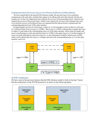
  • 1. Communication between Layers of a Protocol (Protocol Data Units) We have learned that in the layered OSI reference model, the top most layer of two machines communicate with each other virtually (they appear to be talking with each other directly but they are actually not). In fact, the Application layer requests the services of the presentation layer, which in turn requests the services of the session layer, which in turn requests the services of the transport layer and so on until the services of the physical layer are requested and this physical layer communicates the corresponding physical layer of the other machine. In requesting the services of a lower layer, a layer (n+1) will send data to layer (n) that we call Layer (n+1) Protocol Data Unit (or Layer (n+1) PDU). This Layer (n+1) PDU is placed after a header that Layer (n) adds to it and sends to the corresponding Layer (n) in the other machine, which strips the header and uses it in performing its work and send the Layer (n+1) PDU to the upper Layer (n+1) in that machine. If Layer (n) sends information to the lower layer (n–1), that information would be called Layer (n) PDU, which will be placed after the Layer (n–1) header and sent to the corresponding Layer (n–1) in the other machine, and so on. TCP/IP Architecture We have seen in the previous lectures that the OSI reference model is built on having 7 layers that the architecture of the TCP/IP protocol is as shown in the following figure.
  • 2. The different layers in the TCP/IP protocol are not very well structured as it is the case in the OSI reference model where different layers may interact with other layers skipping layers in between. This gives the TCP/IP protocol suite more flexibility. The following figure shows a mapping between the layers of the TCP/IP and the OSI model. Note that this mapping is not fully agreed on where different textbooks and different people use slightly different mappings. Although the TCP/IP protocols are a specific Transport Layer protocol (TCP) that is running on top of a Network Layer protocol (IP), the TCP/IP actually is used to describe a large number of protocols that include the following set of protocols:
  • 3. We see that some of the protocols of the: • Application Layer: Hyper Text Transfer Protocol (HTTP), Simple Mail Transfer Protocol (SMTP), File Transfer Protocol (FTP), Domain Name System (DNS) protocol, and Real‐time Transfer Protocol (RTP). • Transport Layer: Transport Control Protocol (TCP) which is used by HTTP, SMTP, and FTP, and User Datagram Protocol (UDP) which is used by DNS and RTP. • Internetwork Layer: Internet Control Message Protocol (ICMP), Address Resolution Protocol (ARP), Reverse Address Resolution Protocol (RARP), and Internet Protocol (IP) which is used by TCP, UDP, and ICMP. • Network Interface Layer: Many systems exist in this layer including LAN, Token Ring, and Asynchronous Transfer Protocol (ATM). Encapsulation of PDU in TCP/IP As discussed previously, each layer in the TCP/IP protocol stack sends a Protocol Data Unit (PDU) to the lower layer to its services. The lower layer encapsulates (creates a capsule around) the PDU of the upper layer and sends it to the lower layer until it reaches the Network Interface Layer, which transmits it over the network. The encapsulation process includes adding a Header (and possibly a trailer) to the PDU of the upper layer. A major purpose of the headers is to add addressing information, and the trailers to add error detection information.
  • 4. An encapsulation example is shown below where a web‐client (your Internet browser) is requesting a website. This request goes to the lower layers where the transport layer adds port numbers (that allow the web‐client application to communication with the web‐server application) in addition to other information. The internetwork layer adds source and destination IP addresses (that allow the source and destination machines to communicate with each other) in addition to other information. Finally, the network Interface layer adds its own source and destination MAC addresses (that allow the different machines over the link to communicate with each other) in addition to other information, and also adds a trailer (that allows the detection of errors). This is shown in the following example:
  • 5. The Internet Protocol (IP) The Internet Protocol (IP) is the backbone protocol of the Internet. Without it, the Internet would not have evolved to become what it is now. Nevertheless, the IP is very lousy in performing it work. It does not guarantee the delivery of packets, if they arrive, it does not guarantee that they will arrive in order or on time, IP packets are dropped if a specific router becomes congested, error checking is not performed on the data (it is done only on the IP header). So, basically, you use the services of the IP protocol at your own risk. The reason for having the IP protocol’s work being so lousy is that this makes it very simple and puts the complexity at the edges of the network (transfers the complexity from the network to the end machines). There are two flavors of the IP that are in use today. Internet Protocol version 4 (IPv4) is the one that is in wide use now and Internet Protocol version 6 (IPv6) which is the new standard and is now in its experimental phase. IP Version 4 (IPv4) Header The interesting part of the IPv4 protocol is its header, which adds all of the functionally that protocol performs. The header of an IP packet (version 4) is rich in components and is illustrated below: The length of the header is always a multiple of 4 bytes (multiple of 32 bits), with a minimum length of 20 Bytes (160 bits) if no options are present in the header. Therefore, the length of the header can be 20 Bytes, 24 Bytes, 28 Bytes, … and so on. The maximum length of the header is 15*4 = 60 Bytes. What increases the header’s length above than the minimum of 20 Bytes is a set of options that may be added at the end of the header. The following is a description of the different components of the IPv4 header (the length of the component is between parentheses): • Version (4 bits): This is the version of the IP protocol being used which takes values of 4 (for IPv4), 5 (for some a specific type of protocols that is not important in our case), or 6 (for IPv6). So, for the following items, we will assume that the version is 4 as other versions have different header structures. • Internet Header Length (4 bits): This specifies the length of the header in multiple of 4 Bytes. That is, if the header length is the minimum of 20 Bytes, this value will be 5, if the header length is 24 Bytes, this will be 6, and so on. This specifies the maximum length of the header to be 15*4 = 60 Bytes. • Type of Service (8 bits): This is used to indicate specific requirements on the type of service associated with the delivery of the packet such as the priority in delivering this packet, … etc. These options are rarely used and most traffic sent over the Internet has all of these bits set to
  • 6. zero. • Total Length (16 bits): This gives the total length (in BYTES not bits) of the packet including the header. Since this component of the header has length of 16 bits, the maximum length of the packet can be (1111 1111 1111 1111)2 = (65535) Bytes. Therefore, the maximum data you can have in an IP packet is 65535 – 20 = 65515 Bytes (since the minimum header length is 20 bytes). However, this maximum length is rarely used because most physical networks have their own maximum on the length of the frames, and since packets are encapsulated in frames the maximum size of a packet must not exceed what the frame size accepts. For example, Ethernet has a maximum of 1500 Bytes. • Identification (16 bits): This component of the header is used by the IP protocol whenever fragmentation (breaking the packet into smaller pieces called fragments) of a packet is performed. That is, a long packet is fragmented to smaller pieces because the physical network over which the packet is to be transmitted does not support the original long packet. Each fragment will be sent over the network as if it is an independent packet. Since fragments of many packets may be in transit at the same time (the different pieces of many packets are being carried over the network and have not been received yet), an identification that allows the receiving machine to know which original packet does each fragment belong to is needed. The identification will be set to a random number (one value out of a possible of 65536 values can be used) for each original packet (so all the fragments of specific packet will have the same identification number) and this specific identification number is not used again for some time to insure that fragments of the different packets don’t get mixed up (fragments of first fragmented packet with identification x do not get mixed up with fragments of second fragmented packet with identification x). To avoid this, sufficiently long time must pass before reusing the same identification numbers again. If fragments of a specific packet reach a physical network that supports packet sizes smaller than their size, these fragments will be fragmented again. The reassembling of fragments is done only at the destination machine where this machine waits until it receives all fragments of a packet and then reassembles the different components to form the original packet. Once the destination machine receives a fragment of a packet, it sets a timer. If one or more fragments of the packet are lost (they do not arrive before the timer expires), the destination machine will discard the rest of the packet. • Flags (3 bits): One bit of flags is not used. Another bit of the flags is (Don’t Fragment) which is used by the source machine to request from the routers carrying the packet not to fragment that packet. In this situation, if a router finds that it has to fragment a packet because the physical layer over which it will send the packet does not support the size of the packet, it will drop the packet and send back to the source an ICMP message informing it of this situation. The third bit is (More Fragments) which is used by the fragmenting machine to indicate to the destination machine if there are more fragments or not. That is, all fragments except the last one will have this bit set to 1, while the last fragment will have this bit set to 0. • Fragment Offset (13 bits): The identification and Flags indicate which packet do fragments belong to and if there are more fragments coming or not. But they do not indicate the order of fragments (or the location of a fragment inside the original packet). This is done by the fragment offset, where the fragment offset represent the location of the first byte in the fragment within the data of the original packet. Since the fragment offset is 13 bits (giving 213 values) while the total length of the packet is 16 bits (giving 216 values), the fragmentation process is designed such that each fragment (except the last one) must have a size that is multiple of 8. That is, the fragment offset represents the 13 most significant bits of the location of the first byte of the fragment inside the data part of the original packet, where the 3 least significant bits are assumed to be 000. Remember that 216/213 = 8. So, o if Fragment Offset = (0000 0000 0000 0)2, this represents the first fragment because the first byte in the fragment is the byte (0000 0000 0000 0000)2 in the data part of
  • 7. original packet. o if Fragment Offset = (0000 0000 0000 1)2, this indicates that the first byte in the fragment is the byte (0000 0000 0000 1000)2 = 8 in data part of the original packet. o if Fragment Offset = (0000 0000 0001 0)2, this indicates that the first byte in the fragment is the byte (0000 0000 0001 0000)2 = 16 in the data part of the original packet. o And so on. The process of fragmentation and reassembling fragments is shown in the following figure. In the above figure, if the Don’t Fragment flag of the packets sent over Network 1 was set to logic 1, all packets will be dropped by the router and ICMP messages will be sent to the source machine. • Time to Live (8 bits): Sometimes packets get lost in the network where routers have trouble sending them to the destination, so they keep hopping from one router to another aimlessly. If a sufficient number of packets keep hopping in circles for an indefinite amount of time without aim between routers, they may bring down the network. To prevent this from happening, the time to live component is set to a specific value (with 8 bits so it has a maximum value of 255) such that each router that the packet passes over decrements this value by one. If the packet does not reach its final destination before this number reaches 0, the packet is dropped (because most likely it was lost) and an ICMP message is sent back to the source machine to indicate to it that its packet has been dropped. • Protocol (8 bits): This indicates the Transport Layer protocol (TCP, UDP, or even ICMP) that the IP packet is carrying inside of it. • Header Checksum (16 bits): It is very important to make sure that the header which contains addresses and other very important information is free of errors. For this, the IP header contains a checksum (that is computed using a specific method) to detect errors that may occur in the header itself (not the data of the packet). Since there are some components of the header that change as the packet travels between routers such as the Time to Live, this
  • 8. header checksum is recomputed at each router after the modifying the header and the new checksum is used to replace the old one. Source IP Address (32 bits): Contains the IP address of the source machine. Destination IP Address (32 bits): Contains the IP address of the destination machine. Options (variable length): Allows the source machine to request specific features such as the path of routers over which the packet is to travel over. Padding (variable length): This contains no information but it is used to extend the length of the header to insure that it is a multiple of 4 bytes (or 32 bits). The following summarizes the different components in the IPv4 header. IP Addressing There are several organizations in the world that have the authority for assigning IP addresses to institutions that need access to the Internet. When requesting one or more IP addresses, the corresponding organization responsible for assigning IP addresses will assign to the requesting institution one or more IP addresses that belong to one of several IP address classes. Three of these classes are for public distribution, one class is for multicasting, and one class is for experimentation. The five IP address classes are shown below. Class A addresses have their most significant bit being 0, class B addresses have their two most significant bits being 10, class C addresses have their three most significant bits being 110, class D addresses have their four most significant bits being 1110, and finally class E addresses have their five most significant bits being 11110. Note that class A supports very few Network IDs but a large number of hosts per network, class B supports more Network IDs but less number of hosts per network, and class C supports a very large number of networks but few hosts per network.
  • 9. Since IP addresses are 32‐bit long, the total number of theoretical IP addresses is 232 ≈ 4.295 * 109 different IP addresses. Therefore, you can theoretically connect a total number of computers to the Internet that is equal to 4.295 * 109. However, in practice, the above assignment of IP classes is very wasteful. Consider for example the following cases: Class A: Number of Networks ≈ 128, Number of hosts ≈ 16,800,000 Class B: Number of Networks ≈ 16,400, Number of hosts ≈ 65,500 Class C: Number of Networks ≈ 2,100,000, Number of hosts ≈ 256 Class D: Total number of IP addresses reserved for multicasting ≈ 268,000,000, Class E: Total number of IP addresses reserved for experimentation ≈ 134,000,000 Clearly many IP addresses are for multicasting and experimentation purposes. In addition, once an organization requests an IP address range, they are assigned a network ID that belongs to one of the classes A, B, or C above and have full control over the whole set of host IDs. If that organization does not use all of its possible Host Ids, they are theoretically wasted. Note: In fact, this arrangement of IP addresses into classes is OBSOLETE (it is no longer used because it is very wasteful in assigning IP addresses to Internet users). Another system known as Classless InterDomain Routing (CIDR) system was developed to reduce the waste in IP address assignment. Special Addresses There are some special addresses with specific uses and specific meanings. These special addresses are: If (Host ID = 111 … 11) ��� Broadcast the packet to all hosts on the network specified by Net ID If (Net ID = 111 … 11) and (Host ID = 111 … 11) ��� Packet is broadcast on the local network If (Host ID = 000 … 00) ��� Specifies the network specified by Net ID not a specific host If (IP Address = 000 … 00) ��� Used for identifying someone’s own IP address from the MAC address If (IP Address = 127.x.x.x) ��� Used for loopback (packet does not reach the network card of the source machine but loops back to the same machine) Also, some addresses have been reserved for use in private LANs (one set of addresses for each of the classes A, B, and C) where such addresses are not routed by Internet routers (routers in the Internet discard any IP address in these ranges) Range 1: 10.0.0.0 to 10.255.255.255 (class A) Range 2: 172.16.0.0 to 172.31.255.255 (class B)
  • 10. Range 3: 192.168.0.0 to 192.168.255.255 (class C) Network address translation (NAT) is used to translate between private IP addresses and global IP addresses Network Address Translation (NAT) The concept of NAT is a very powerful concept for several reasons: It shields computers in a private LAN from the Internet and therefore reduces the risks that are associated with connecting a computer to the Internet (hacking attacks). More importantly, Internet service providers usually assign one IP address to a home network or multiple IP addresses to an organization. However, the number of computers on the home network. What NAT does is that local addresses (in one of the 3 ranges of private IP addresses that start with 10, 172, or 192) are translated to one public IP address assigned to the home network (in the case of DSL service) or multiple public IP addresses assigned to the organization by the Internet service provider (in the case of organizations such as KFUPM ). The NAT system also translates from the public IP address(es) to the corresponding private IP addresses as the packets arrive from the Internet to the private network. In fact, all computers in a network that uses NAT appear to the outside world as having only few IP addresses. For the case of a home network, all computers in your home network will appear to the outside world as having a single IP address. If you visit a website that records your IP address from one of your home network computers and then try to visit the same website from another computer, the website will not be able to distinguish between the two computers. The following are two examples that show how NAT works. In the first case, the network is assigned multiple public IP addresses equal to the number of machines in the network. All that the NAT does is translate each private IP address into one of the public IP addresses and vice versa. The two situations for outgoing packets (packets going from the private network to the Internet) and incoming packets (packets going from the Internet to the private network) are shown below. In the second case, the network is assigned a single public IP address that will be used by all computers in the private network. The two situations for outgoing packets and incoming packets are shown afterwards.
  • 11.
  • 12.
  • 13. Subnet Addressing The subnetting process involves adding another hierarchy (level) to the hierarchical IP address. We learned that the IP address contains two parts: Network ID and Host ID. A network administrator usually has not control over the Network ID as it is assigned by the Internet service provider or by one of the institutes that are authorized to assign IP addresses to requesting organizations. However, the network administrator is fully in control of the Host ID part of the IP address. Instead of creating what appears to be a single network for the complete organization even if it consists of a large number of machines, a network administrator can subdivide the Host ID part of the IP address into two parts: Subnet ID and Host ID. By doing this, a third hierarchical level is added to the IP address such that now it contains the 3 levels: Network Id, Subnet ID, and Host ID. The Subnet ID subdivides the single network into smaller networks that are called subnets. Each of these subnets contains its own set of hosts. The great thing about subnetting is that it is transparent (not seen) to the outside world and a computer on the Internet would not have to do any extra work to access a computer in a subnetted network. The following figure shows an original IP address in Class B before and after subnetting. It also shows the corresponding subnet mask. The subnet mask contains a series of 1s that start from the most significant bit of the IP address and stop at the end of the Subnet ID. The subnet mask contains 0s in the bits corresponding to the Host ID as shown below.
  • 14. Subnetting Example: Consider the simple network shown below. This network is connected to the Internet through the connection shown to the left. Assume that you are assigned IP addresses in Class B with the 14 bits of the network ID being (11 0000 0110 0000)2 , and you have decided to use a Subnet Mask that reserves 4 bits of the Host ID for the Subnet ID and leaves 12 bits for the Host ID for the hosts: 11111111 11111111 11110000 00000000. Show a possible IP address assignment for the different computers, routers, and show the different subnets indicating on each subnet its subnet address.
  • 15.
  • 16. IP Routing Routing is the process performed by routers to transfer packets from the source machine to the destination. Unlike switches, routers are configured by a network administrator. Routers share information about the different routes and the health of each router among themselves so that all of them can draw a picture of the whole network. Each router stores a table known as Routing table that contains information about the different routes that the router can send the packet through. Each machine on the network has some form of routing table. Routing tables in hosts (computer) usually have few entries (5 to 10 entries) depending on the number of network interface cards installed. Routing tables in Internet routers may have 100,000 different entries or possibly more. Format of a Routing Table Consider the following network (designed in the previous lecture). There are two routers (Router 1 and Router 2). Let us look at the format of the routing table in these routers. 2 A typical routing table may look something like the following:
  • 17. Destination Next Hop Flags (H = 1 ��� Destination is a Host) (H = 0 ��� Destination is a Network) (G = 1 ��� Next Hop is a Gateway/Router) (G = 0 ��� Next Hop is not Gateway/Router) Network Interface Metric Destination: This list the IP addresses of the possible destinations that the router knows how to route a packet to. Next Hop: This gives the next IP address that the packet will be transmitted over. Flags: These provide information about the devices that are connected to the router (gateway/router or not) and the type of destination (host or network). Network Interface: The port that the router will send the packet over. Metric: A measure of the quality of the link to help determine the most efficient link over which to send the packet. Types of Destinations: Generally, there are 3 types of destinations that can be found in routing tables: Complete Destination IP Address: This represents the complete destination IP address in the packet. Destination Network ID: This represents the network ID of destination IP address of the packet. Default Gateway: This is where packets with destination IP addresses and Network IDs that are not found in the routing table will be sent. Order of Searching the Routing Table 1. Destination column is searched to determine if the table contains an entry with the complete destination IP address ��� If found, IP packet is forwarded along the next hop using the proper network interface 2. If the above was not found, the routing table is searched for the destination Net ID ��� If found, IP packet is forwarded along the next hop using the proper network interface Address Resolution Protocol (ARP) This protocol is used in networks such as Ethernet. To transmit frames in Ethernets, MAC addresses are used which have the format (xx:xx:xx:xx:xx:xx) where each (x) is a hexadecimal number. MAC addresses are unique to each computer in the world since these addresses are linked to the Network Interface Cards (NIC). So, a computer that would like to send a packet to another with a specific IP address on the network would broadcast an ARP packet on network asking all computers a question that looks like “To the machine with IP address x.x.x.x, please inform me (where my MAC address is xx:xx:xx:xx:xx:xx) about your MAC address”. The computer with the particular IP address x.x.x.x will respond only to the requesting computer with its MAC address. Reverse Address Resolution Protocol (RARP) In specific cases, a host on the network may know the MAC address but not the IP address. In this situation, a reverse process to that done in the ARP is used to get the IP address assigned to the machine. So, a host may use the RARP protocol to ask the question that looks like “Machine with MAC address xx:xx:xx:xx:xx:xx, please inform me of the corresponding IP address”.
  • 18. Internet Control Message Protocol (ICMP) This protocol is responsible for sending control and error messages over the Internet. In many cases, routers fail to route a specific packet to its destination as in the cases: The Time‐to‐Live counter reaches zero for a specific packet before it reaches its destination. A router searches its routing table but could not find where to route the packet A router needs to fragment a packet because the physical network supports smaller packets but the Don’t Fragment flag bit is set to 1. TCP Connection Establishment The TCP connection is established in three steps 1. Host A send a connection request (SYN) to Host B indicating the initial sequence number (Host A ��� Seq_No = x ��� Host B) 2. Host B acknowledges the request by sending an (ACK) with an ACK number that is one higher than x and a request to initiate its own connection with a sequence number of y (Host B ��� Ack_No = x+1 ��� Host A) (Host B ��� Seq_No = y ��� Host A) 3. Host A responds with its own acknowledgment by sending an (ACK) with an ACK number that is one higher than y (Host A ��� Ack_No = y+1 ��� Host B) The following figure illustrates the establishment of TCP connections.