SlideShare uma empresa Scribd logo
1 de 48
GNS3
                                     Graphical Network Simulator
                                     By Mike Fuszner – version 1.0


GNS3 is a Graphical Network Simulator that allows emulation of
complex networks. You may be familiar with VMWare or Virtual PC
that are used to emulate various operating systems in a virtual
environment. These programs allow you to run operating systems
such as Windows XP Professional or Ubuntu Linux in a virtual
environment on your computer. GNS3 allows the same type of
emulation using Cisco Internetwork Operating Systems. It allows you
to run a Cisco IOS in a virtual environment on your computer. GNS3 is
a graphical front end to a product called Dynagen. Dynamips is the
core program that allows IOS emulation. Dynagen runs on top of Dynamips to create a more user friendly,
text-based environment. A user may create network topologies using simple Windows ini-type files with
Dynagen running on top of Dynamips. GNS3 takes this a step further by providing a graphical environment.

GNS3 allows the emulation of Cisco IOSs
on your Windows or Linux based
computer. Emulation is possible for a
long list of router platforms and PIX
firewalls. Using an EtherSwitch card in a
router, switching platforms may also be
emulated to the degree of the card’s
supported functionality. This means
that GNS3 is an invaluable tool for
preparing for Cisco certifications such as
CCNA and CCNP. There are a number of
router simulators on the market, but
they are limited to the commands that
the developer chooses to include. Almost always there are commands or parameters that are not supported
when working on a practice lab. In these simulators you are only seeing a representation of the output of a
simulated router. The accuracy of that representation is only as good as the developer makes it. With GNS3
you are running an actual Cisco IOS, so you will see exactly what the IOS produces and will have access to any
command or parameter supported by the IOS. In addition, GNS3 is an open source, free program for you to
use. However, due to licensing restrictions, you will have to provide your own Cisco IOSs to use with GNS3.
Also, GNS3 will provide around 1,000 packets per second throughput in a virtual environment. A normal router
will provide a hundred to a thousand times greater throughput. GNS3 does not take the place of a real router,
but is meant to be a tool for learning and testing in a lab environment. Using GNS3 in any other way would be
considered improper.

GNS3 was developed primarily by Jeremy Grossmann. Additional developers involved in creating GNS3 are
David Ruiz, Romain Lamaison, Aurélien Levesque, and Xavier Alt. Dynamips was developed by Christophe
Fillot. Dynagen’s primary developer was Greg Anuzelli. There are a lot of other people that have assisted in
various ways in the development of these products. Development is an ongoing process as each product
evolves.

This documentation will begin with a Quick Start Guide followed by a more in-depth discussion. Finally, in this
introduction, I’d like to list a variety of Web sites that you will find useful:

   http://www.gns3.net                                           GNS3’s primary Web site
   http://wiki.gns3.net                                          GNS3’s Wiki site
   http://www.ipflow.utc.fr/index.php/Cisco_7200_Simulator       Dynamips – the actual emulator
   http://www.ipflow.utc.fr/blog/                                Dynamips blog
   http://dyna-gen.sourceforge.net/                              Dynagen
   http://www.ipflow.utc.fr/bts/                                 Dynamips/Dynagen bug tracking
   http://7200emu.hacki.at                                       Hacki’s forum

The most useful sites will be www.gns3.net and http://7200emu.hacki.at. The GNS3 site will be specific to
GNS3. However, the hacki site is an invaluable forum where you’ll find many how-to’s and be able to interact
with other users. I highly recommend that you visit both sites.
GNS3 Quick Start Guide for Windows Users

This section will take you through the steps to get started with GNS3 in a Windows environment. All of the critical and
most important things to know will be covered, but for an in-depth discussion, see later sections of this document. If you
use Linux, there is a GNS3 Quick Start Guide for Linux Users in the next section.

Step 1: Download GNS3.

Use your Web browser to access
http://www.gns3.net.

Click on the green Download button.


The easiest way to
install GNS3 in a
Windows
environment is to
use the top file:
GNS3-0.5-win32-
all-in-one.exe.

Click on Mirror 1 or
Mirror 2 to begin
the download.
Click the Save button and then choose a location on your hard drive
to save the file.


Your download will begin. The file is a little under 10 MB in size and
will take less than minute to download on a DSL or cable
connection. Dial-up connections will take somewhat longer.


Step 2: Install GNS3

Find the file you download and double-click on it to begin installing
GNS3.

The GNS3 Setup Wizard will begin. Click the Next button.


Click the I Agree button to continue.
Allow GNS3 to create a Start Menu folder with the default name
GNS3 by clicking the Next button.


GNS3 depends on several other programs to operate. Those
dependencies include WinPCAP, Dynamips, and Pemuwrapper. These
components along with GNS3 are all chosen by default for
installation, so just click the Next button to continue.


A default location is chosen for GNS3. Click the Install button to
accept the default location and to begin the actual installation of
files.


The first dependency for GNS3 is WinPcap. Click the Next button to
begin the WinPcap Setup Wizard.
Click I Agree to accept the License Agreement for WinPcap.

The installation for WinPcap will begin. However, if you have a
previous version of WinPcap on your computer, the wizard will ask
to remove the older version and will then install the newer version.


After WinPcap is installed, the GNS3 Setup Wizard returns to
installing GNS3.


When the wizard finishes, you may uncheck Show Readme and then
click the Finish button.


You have now completed the installation of GNS3.
Click the Start button, All Programs, GNS3, and then
choose GNS3 out of the list of applications installed.
You’ll see the main GNS3 window. We’ll discuss its
panes in a later step, but first we have to configure
the location for a Cisco IOS.
Step 3: Defining Cisco IOS files

As mentioned earlier, you must provide your own Cisco IOS to use with GNS3 due to licensing issues. GNS3 is meant to
be used in a lab environment for testing and learning. Once you have obtained your own copy of a Cisco IOS for one of
the supported platforms, you are ready to continue. Current platforms supported include:

    1710                                        2611                                    2691
    1720                                        2611XM                                  3620
    1721                                        2620                                    3640
    1750                                        2620XM                                  3660
    1751                                        2621                                    3725
    1760                                        2621XM                                  3745
    2610                                        2650XM                                  7200
    2610XM                                      2651XM

On the Edit menu, choose IOS image and hypervisors.


Under the IOS Images tab, click           and then find your Cisco IOS
file and click Open. The file will appear as your Image file.
Next, click the drop-down arrow next to Platform and choose the
platform that corresponds to your IOS file.


Now click the drop-down arrow next to Model and choose the
model corresponding to your IOS file.


For now, we’ll accept the default values that
remain. However, there is a very important value
called the IDLE PC value that we will want to
include. We’ll get to that later.

Click the Save button and then the Close button.
This will return you to the default GNS3 window.

It’s time to create our very first simple topology.
But before that, the next section will present a
GNS3 Quick Start Guide for Linux Users.
GNS3 Quick Start Guide for Linux Users
Let’s turn our focus to Linux users now. Our examples will use Ubuntu. Anyone can download Ubuntu from
www.ubuntu.com for free – it just may take awhile since it’s a large file. Performance is somewhat better in a Linux
environment, but the difference is not significant. First, we’ll install necessary dependencies.

Step 1: Install necessary dependencies

Open the Synaptic Package Manager.
Go to the System menu, then
Administration, and finally Synaptic
Package Manager.


Click the Search button in the toolbar,
type python-qt4 in the Search box and
click the Search button.
When you find python-qt4, click on the
white box in front of it, and choose Mark
for Installation.


Click Mark and the click the Apply button in the toolbar.


On the Summary window, click Apply.
Step 2: Download GNS3.

Use Firefox to access http://www.gns3.net.

Click on the green Download button.


You may choose any of the source
archives for Linux. We will use GNS3-0.5-
src.tar.gz.

Click on Mirror 1 or Mirror 2 to begin the
download.

By default, the file will be downloaded
to the desktop.


Next, right-click on the file on the desktop, GNS3-0.5-
scr.tar.gz, and choose Extract Here.
You’ll see a new icon on the desktop labeled
GNS3-0.5-src.


Now we need to download the latest Dynamips binary for
Linux. Use Firefox to visit the Dynamips blog Web site at:
www.ipflow.utc.fr/blog/

In our example, it is found farther down the page as 0.2.8-
RC2 binary for Linux x86 platform.


Drag the downloaded file, dynamips-0.2.8-RC2-
x86.bin into the GNS3-0.5-src folder.
Let’s change the Dynamips permissions to allow
execution. Double-click on dynamips-0.2.8-RC2-
x86.bin and choose Properties.


Click on the Permissions tab, and then click the box next to Execute: Allow
executing file as program. Then click Close.


Step 3: Configuring GNS3

Double-click the gns3 icon to start the application. Click the Run
button.


The Setup Wizard begins with a message as shown.
Click on the big number 1 to open the Preferences window
(actually located under the Edit menu in GNS3).
Then click Dynamips in the left-hand pane.

Click the ellipses next to Executable path and then
click dynamips-0.2.8-RC2-x86.bin and followed by
the Open button.


When you return to the Preferences screen, click
OK.


Now you return to the Setup Wizard. Click the big number 2 to
open the IOS images and hypervisors window (actually located
under the Edit menu in GNS3).
Use the ellipses button next to the Image file box
to locate an IOS image.


As mentioned earlier, you must provide your own
Cisco IOS to use with GNS3 due to licensing issues.
GNS3 is meant to be used in a lab environment
for testing and learning. Once you have obtained
your own copy of a Cisco IOS for one of the
supported platforms, you are ready to continue.
Current platforms supported include:

    1710                                       2611                                       2691
    1720                                       2611XM                                     3620
    1721                                       2620                                       3640
    1750                                       2620XM                                     3660
    1751                                       2621                                       3725
    1760                                       2621XM                                     3745
    2610                                       2650XM                                     7200
    2610XM                                     2651XM

Then click the Save button followed by the Close button. You’ll return again to the Setup Wizard window. Click OK to
finish.

It’s time now to create our first simple topology. So whether you are Windows user or a Linux user, continue to the next
section. We have often used screen shots from Windows when describing GNS3 usage, but the screen shots from Linux
would look identical except for the title area.
Creating the Simplest Topology
We describe how to build a more complex topology later, but for now, let’s just learn how to place one router on the
desktop, start it, and console into it. We will then learn how to find an idlepc value for the IOS we are using. This is a very
important step. When an IOS is running, it will consume up to 100% of your CPU time. This will cause your computer to
become very sluggish and will prevent building more complex topologies. However, if we use an idlepc value, we can
reduce CPU usage dramatically. It puts the IOS into a sleep state when it is not in active use and wakes it up only when it
is necessary. A more technical explanation will be given later.

The GNS3 window is divided into four panes by default.
The left-most pane lists the types of nodes available. You
will see router icons for the various platforms, a PIX
firewall, Ethernet switch, ATM bridge, ATM switch,
Frame Relay switch, and Cloud. Other node types may be
added as explained later.

The right-most pane will provide a topology summary
that will be better understood when we built more
complex topologies. For now, just know that the pane
exists.

The middle section contains two panes. The top pane is
your work area where a topology may be graphically
built. The bottom pane, called the Console, shows
Dynagen at work. Dynagen, as you recall, is the text-based front
end to Dynamips, the core emulator being used. Learning how to
use Dynagen is like learning how to use DOS the first time, so we
will not get into that here. However, we will use a very few
simple but useful commands in the Dynagen pane.

Click on a router icon under Nodes Types corresponding to the
IOS platform you are using. In our example, we are using a 7200
platform. You must use a platform for which you defined an IOS.
Drag an appropriate router node type over to the workplace
pane in the middle and let go. We now have a router ready to
configure.


Right-click the router and choose Configure.
Click on R1 and then the Slots tab. Click the
drop-down arrow next to slot0 and choose an
adapter that says FE at the end. This will add a
FastEthernet adapter to the router. Next, click
the drop-down arrow next to slot1 and
choose PA-4T+. This will add four serial
interfaces to the router. Click OK.
(Note: If you do not have these exact
adapters, just choose something close.)


Right-click the router and choose Start.

Right-click the router again and choose Console. A telnet
console opens up.

(Note: In Windows Vista, the telnet client is not automatically
installed as in previous versions of Windows. Click on the Start
sphere and choose Control Panel. Click on Programs. Under
Programs and Features, click on Turn Windows features on or
off. Click next to Telnet Client to place an x in the box. Click
OK.)


You may need to press Enter once initially
in the Console window. When asked
“Would you like to enter the initial
configuration dialog?”, enter no and press
Enter. Wait for the router to settle down at
a Router> prompt. You may need to press
Enter once or twice to get there.
After the router has settled down to a
Router> prompt, return to the main GNS3
window.


Right-click R0 and choose Idle PC. GNS3 will spend a moment calculating
an Idle PC value before presenting the screen to the right. If you click the
drop-down arrow, you see a list of possible idlepc values. Potentially
better idlepc values are marked with an asterisk. Choose one of the values
with an asterick (in our example, we will choose number 4) and click OK.

You’ll receive a confirmation that the idlepc value has been applied.

If you choose IOS images and hypervisors on the Edit menu, and double-
click on the image under the IOS Images tab, you’ll see the new idlepc
value displayed under Settings.


You may repeat this process to find the
value that reduces CPU usage the most.
To observe CPU usage in Windows, press
Ctrl+ALT+DEL and choose Task Manager.
Click on the Performance tab to view
CPU usage. In Ubuntu, choose System
Monitor under Administration on the
System menu. Click the Resources tab.


You will observe that without an idlepc value, CPU usage will be at or near 100%,
but with an idlepc value, CPU usage will drop to a very low value.
Enjoy using your router!

You may now return to your telnet window
to use your router. You are actually running
the Cisco IOS that you chose. All commands
supported by the IOS are available.

Remember earlier we chose a FastEthernet
adapter and a four-port serial adapter. If you
issue the show ip interface brief command as
shown, you’ll see the designations for these
four ports on the router. In our example,
they are fa0/0, s1/0, s1/1, s1/2, and s1/3 (in
abbreviated form).
GNS3 Main Interface
Before continuing you may want to take a moment to view the following labeled graphics:


Drop-down menu from right-clicking on a router:
Building More Complex Topologies
Although a single router is useful to get familiar with commands, it would be nice to build more complex topologies.
With GNS3 very complex topologies may be built. Just as performance when running virtual machines within VMware or
Virtual PC depends on your computer resources, running many router instances will affect the performance of your
computer. The faster your CPU and the more RAM that you have, the better. However, idlepc does a lot to help with
CPU usage. Ghostios and sparsemem are two additional utilities that will help with RAM usage. Ghostios is enabled by
default in GNS3. Sparsemem must be enabled, since it is off by default. These will be discussed in detail in the section on
Memory Usage. As an example, with 2 Gigabytes of RAM and a 2.5 GHz processor, you should have no problems running
a lab with good performance with a half dozen routers and several workstations.

Let’s build the topology shown with three routers. Start GNS3. Drag
three routers running an IOS you have configured into the
workspace. Right-click each router and choose Configure. Under the
Slots tab, include a FastEthernet adapter and PA-4T serial adapter.

Now we’re ready to connect the routers together. Click the Add
a link button on the toolbar at the top. Choose Manual from the
drop-down menu. Your cursor will change to a cross.

Click on R0 and select s1/0 – then click on R1 and select s1/0.
Click on R1 again and select s1/1 – then click on R2 and select
s1/1.

Now click the Add a link button again (now it looks like a red
Stop sign with an X. After clicking on it, the icon will change
back to a connector look.


Notice the right-pane call Topology Summary. Your connections are
now available for viewing by clicking the plus next to each router.

GNS3 gives each router a default name beginning with R. If you would
like to change the name, right-click on a router and choose Change the
hostname. For this example, we will continue to use the default names.

There are four buttons on the toolbar at the top:


The first button is the Telnet to all IOS button. The next three buttons are the Start/Resume all IOS, Suspend all IOS, and
Stop all IOS. The links are all red. Let’s start the routers by clicking the Start/Resume all IOS
button on the toolbar. A box will pop up indicating the routers are being started, and the links
will turn green. If we click the Telnet to all IOS button, we may observe the boot-up process of
each router. A separate console window will open for each router.

Answer No and press Enter for each router at the question “Would you like to enter the initial configuration dialog?”.

You may now configure each router. In our example, we will change the hostnames, configure the secret password,
enable synchronous logging, assign IP addresses to the interfaces and turn them on, enable RIP version 2, and finally test
connectivity by using pings.
As you can see, East can ping West which verifies connectivity from end-to-end. You may also see that East has the
10.0.0.0/24 network in its routing table.

Now let’s drag three Ethernet switches and place one under each router. Use the Add a link button to add a connection
from each router’s Fa0/0 port to port 1 on each switch. Note that the built-in Ethernet switch has 8 ports. They may act
as access ports or dot1q trunking ports. By default, they act as access ports. If you right-click a switch and choose
configure, you’ll see that you may specify several options. We will use the default values. If you wish to configure more
advanced options with switches, then you’ll need to add a router with an NM-16ESW EtherSwitch adapter. These
adapters support many more switching functions but not all. We’ll discuss EtherSwitch adapters in a later section.

It’s time to add PCs to your topology.
Adding PCs to Your Topology
There are three possible ways to add a computer to your topology. If you just need to check for connectivity using ping
or traceroute, the best way is to use the Virtual PC Simulator. You may also add another router but configure it to act
like a PC. Finally, you may use your real PC.

Using the Virtual PC Simulator (and the Symbol Library)

The Virtual PC Simulator is a program that runs within Windows or Linux. It has limited functionality, but most
important, it allows pings and traceroutes. These are the most common testing commands used during CCNA or CCNP
training and are often the only commands needed. Using VPCS you will save memory and CPU cycles. If you do not need
more functionality in a workstation within your topology, I highly recommend VPCS. The Virtual PC Simulator is a free
product available at the following Web site: http://wiki.freecode.com.cn/doku.php?id=wiki:vpcs

Extract the archive to your PC, and then in Windows run vpcs.exe.

If you are running Linux, right-click the vpcs (not vpcs.exe)
and choose Properties.

Click on the Permissions tab. Then click on the box next to
Execute. Click Close.


                                                          Now right-click the desktop and choose Create Launcher.
                                                          Click the down arrow next to Type and choose Application in
                                                          Terminal. For Name, type VPCS. For Command, you may browse
                                                          to the vpcs program. For Comment, type Virtual PCs. Click OK.
                                                          Now just click the VPCS icon on your desktop.


It is best to open the Virtual PC Simulator before
starting GNS3.
For help, just type ? at the prompt.
VPCS supports up to nine PCs. Just
type a number to switch to another
PC. Use the Show command to
view a PC’s IP or MAC address. To
assign an IP address, subnet mask,
and default gateway to a PC, follow
this format at the prompt:

ip 10.0.0.5 10.0.0.1 24

The above command assigns the
PC an IP address of 10.0.0.5 with a
/24 subnet mask and a default
gateway of 10.0.0.1. To switch to
PC2, just type a 2 and press Enter.
The program is very easy to use.
You’ll find more information at the above Web site.

To integrate VPCS into GNS3, we will first make use of
the Symbol Library. Choose Symbol Manager on the Edit
menu after opening GNS3.

Click the computer symbol under Available symbols, then
click right arrow button between the windows. This will
move the symbol into the Customized nodes column. In
the Name box, type computer. Use the drop-down arrow
to change the type to Cloud, if necessary. Click the Apply
button. Then click OK. In the GNS3 Nodes Types column,
you should now see a computer icon.


Drag three computers into the workspace, placing one
below each switch. Right-click the computer under West,
and choose Configure. Click on C0 under Clouds. Click the
NIO UDP tab.

Type in the following values under Settings:

Local port: 30000
Remote host: 127.0.0.1
Remote port: 20000

These settings correspond to VPCS 1. Click the Add button
and then OK.
Now right-click each of the other computers and choose Configure.
Use the following settings:

Computer        Local port       Remote host       Remote port
C1              30001            127.0.0.1         20001
C2              30002            127.0.0.1         20002

We have just configured each of the computers as clouds that
connect with GNS3 through the UDP ports designated. Before we can
connect our VPCs to our switches, we’ll need to add a port to each
switch. Right-click each switch and choose Configure. Click on the
switch (SW0, SW1, or SW2), change Port setting to 2, and click the
Add button and then OK.

Now click the Add a link button on the Toolbar and choose Manual. Connect port 2 of each switch to its corresponding
VPC’s nio_udp port. Click the Add a link red stop sign button to stop adding links.

Now configure the VPCs within the VPCS window.
Configure IP address, default gateway, and subnet mask
(24) for each PC with the values shown in the topology.

Here are the commands that you would use:


Return to each router’s console window to configure its FastEthernet port. Use the addresses shown in the topology
above. Be sure to use no shutdown to turn on the interface. Then add the network to RIP with the router rip command
and network command.

The routes should show up shortly in the routing tables. Try to ping from West’s computer to East’s computer. This ping
should work. A ping from West’s computer to Central’s computer should also work.

Using a Router that Acts Like a PC

You may also simply add another router to your topology and configure it to act like a PC. This method would use more
memory and processor cycles than the previous method, so I would only recommend this method as a secondary choice.

Just add a router and enter the following commands:

Router(config)# no ip routing                                       Turns off IP routing function
Router(config)# interface fa0/0                                     Switches to FastEthernet interface
Router(config-if)# ip address address subnet_mask                   Assigns IP address and subnet mask to interface
Router(config-if)# no shutdown                                      Turns interface on
Router(config-if)# exit                                             Returns to global configuration mode
Router(config)# ip default-gateway gateway_address                  Configures the default gateway
Router(config)# ip http server                                      Optional – starts http server process

Connect the router (acting as a PC) to the rest of your topology.
Using your Real PC – Talking to Real Networks

One of the interesting things about GNS3 and Dynamips is that you can connect your topology to the real world. For
some of your CCNA and CCNP studies you may need to run an actual Web browser or Cisco’s Security Device Manager
(SDM) among others. Just connect your topology to your real PC. You could even connect to virtual machines running on
your computer inside VMware or Virtual PC. I’ve even set up two copies of Windows XP Professional running inside
VMware virtual machines. Then I ran Cisco soft IP Phones that could talk to themselves. You could connect your virtual
network to a real network as well. Connecting a virtual topology running within GNS3 and Dynamips to real devices is
very exciting, but again, your throughput is going to be limited compared to using real equipment for the entire
topology. It only makes sense to use GNS3 and Dynamips in a lab environment and for learning purposes. Any other
usage is highly discouraged!

Connecting your topology to your real PC is very similar
to the process used with the Virtual PC Simulator above.
Drag a computer (defined as cloud) into your workspace.
Right-click the computer and choose Configure. Click on
C0 under Clouds, but choose the NIO Ethernet tab.
Administrator rights are required (root account under
Linux).

For Windows users, click on the box directly beneath
Generic Ethernet NIO, and choose the network adapter
you wish to use. For Linux users, click on the drop-down
box to choose your network adapter (either your real
adapter or a loopback adapter).

Click the Add button and OK. You will need to configure
the IP settings for your computer’s adapter, and then use the Add a link toolbar button to create your connection.

You may use your regular network adapter, but I usually create an MS Loopback adapter to connect to. In Windows, use
the Add Hardware wizard in Control Panel. Choose “Yes, I have already connected the hardware.” On the next screen,
choose Add a new hardware device at the end of the list and click Next. Choose to “Install the hardware manually…” and
click Next. Choose Network Adapters in the list and click Next. Choose Microsoft as the manufacturer and then Microsoft
Loopback Adapter as the network adapter. Finish the wizard. Then right-click My Network Places and choose Properties.
You may wish to rename the new Local Area Connection as MS Loopback Adapter. Also, assign the proper IP settings to
the adapter in order to connect to your topology. Linux has a built-in loopback adapter already installed.
Using Terminal Programs Like PuTTY or TeraTerm
By default, GNS3 uses the telnet application built into Windows or Linux. But if using Windows, you may prefer to use
PuTTY or TeraTerm. Both of these terminal emulators are free to download at one of the following Web sites:

PuTTY:          http://www.chiark.greenend.org.uk/~sgtatham/putty/
TeraTerm:       http://hp.vector.co.jp/authors/VA002416/teraterm.html

Just download the terminal program you prefer and install it on your
computer. Inside GNS3, choose Preferences under the Edit menu. Choose
General in the left pane, and the change the Terminal command box to
read:

For PuTTY:              c:puttyputty.exe -telnet %h %p
For TeraTerm:           c: TTERMPROttssh.exe %h %p /W=%d /T=1

The above commands should be adjusted to point to the location where
installed the program. Note that with PuTTY instead of the built-in telnet
client, your router name will appear in the title bar of the window.

However, my recommendation for Linux users is to use Konsole-KDE4. That is explained below.


WinTabber (Multiple tabs for Windows)
If you are using a topology that opens
several console windows, it becomes a
bit of a challenge switching from one
device to another. You may
consolidate all of these windows into
one application where the windows
are located under tabs. There are
several ways to do this, but the
program I like is called WinTabber. It’s
another free download at the
following site:

http://www.wintabber.com/

Note: WinTabber works with Windows
2000/XP/Vista. Since Wintabber is only
a Windows program, I recommend
Konsole for Linux users.
Konsole (Multiple tabs for Linux)
If you are using a topology that opens several console windows, it becomes a bit of a challenge switching from one
device to another. You may consolidate all of these windows into one application where the windows are located under
tabs. For Linux users, I recommend using Konsole, but the version is very important. If you open Konsole and then
choose About Konsole under the Help menu, your version should be 2.0 or greater (using KDE 4.0 or greater). It is
installed automatically if you are using the KDE4 desktop. If you are using the GNOME desktop (the default in Ubuntu),
then you will need to install Konsole using KDE4.

Synaptic Package Manager is a Linux tool
that finds, installs, or removes software.
Let’s use it to find and install Konsole
using KDE4. Click on Synaptic Package
Manager under Administration on the
System menu.


Click the Search button and look for konsole-kde4.


Right-click konsole-kde4 and choose Mark for
installation.
Click Apply on the toolbar. Then click the Apply
button on the Summary window.


The package files are downloaded and installed, and the final changes are applied.


Next, open GNS3 and choose Preferences on the
Edit menu.
Choose General in the left-hand pane of the Preferences window.

For Terminal command, use the following:
/usr/lib/kde4/bin/konsole --new-tab -p tabtitle=%d -e telnet %h %p >/dev/null 2>&1 &
Click OK to commit the change.


Now when you console into a device, you’ll have each window in a tab along the bottom. Just click the tab to switch to
another window or device.
Memory and CPU Usage
When you use a topology with multiple devices, issues of memory usage and CPU usage occur. To address the CPU
usage issue, an idle-pc value needs to be included. This value is dependent on the IOS version and not the PC. To address
memory usage, ghostios and sparsemem must be included.

Memory Usage

Labs can consume a large amount of real and virtual memory. The “ghostios” and “sparemem” options were added to
address both of these issues, respectively.


The Ghostios option can significantly reduce the amount of real host RAM needed for labs with multiple routers running
the same IOS image. With this feature, instead of each virtual router storing an identical copy of IOS in its virtual RAM,
the host will allocate one shared region of memory that they will all utilize. So for example, if you are running 10 routers
all with the same IOS image, and that image is
60 MB in size you will save 9*60 = 540 MB of
real RAM when running your lab. Ghostios is
enabled, by default, in GNS3.

The “sparsemem” feature does not conserve
real memory, but instead reduces the amount
of virtual memory used by your router
instances. This can be important, because your
OS limits a single process to 2 GB of virtual
memory on 32-bit Windows, and 3 GB on 32-bit
Linux. Enabling sparsemem only allocates virtual
memory on the host that is actually used by the
IOS in that router instance, rather than the
entire amount of RAM configured. This can
allow you to run more instances.

Both features rely on mmap, so this must also
be enabled. Select Preferences under the Edit
menu within GNS3. Check the appropriate
boxes to enable these features.

CPU Usage

We talked about CPU Usage a bit earlier when we learned how to determine idlepc values. Without idlepc values
configured, you may have noticed that your system’s CPU was running at 100%. This is because Dynamips, the core
emulator running under GNS3, does not know when the virtual router is idle, and when it is performing useful work. The
“idlepc” command performs analysis on a running image to determine the most likely points in the code that represent
an idle loop in the IOS process. Once applied, Dynamips “sleeps” the virtual router occasionally when this idle loop is
executed. This significantly reduces CPU consumption on the host without reducing the virtual router’s capacity to
perform real work.

IdlePC values are particular to an IOS image. They will be different for different IOS versions, and even for different
feature-sets of the same IOS version. However idlepc values are not particular to your host PC, operating system, or to
the version of Dynamips that GNS3 is using. It is possible that Dynamips will not be able to find and idlepc value for an
image, or that the values it does find do not work. If this happens, try repeating the process again.
To determine an idlepc value for a given IOS, start
GNS3. Drag only one router set up to use the IOS
version you are trying to configure. Right-click the
router and choose Start. Then right-click the router and
choose Console. You may need to press Enter once
initially in the Console window. When asked “Would
you like to enter the initial configuration dialog?”, enter
no and press Enter. Wait for the router to settle down
at a Router> prompt. You may need to press Enter once
or twice to get there.


After the router has settled down to a Router> prompt,
return to the main GNS3 window.


Right-click R0 and choose Idle PC. GNS3 will spend a
moment calculating an Idle PC value before presenting
the screen to the right. If you click the drop-down
arrow, you see a list of possible idlepc values.
Potentially better idlepc values are marked with an
asterisk. Choose one of the values with an asterick (in our example, we will choose number 4) and click OK.


You’ll receive a confirmation that the idlepc
value has been applied.

If you choose IOS images and hypervisors on
the Edit menu, and double-click on the image
under the IOS Images tab, you’ll see the new
idlepc value displayed under Settings.

When searching for the best idlepc value, it is
a good idea to monitor your CPU usage. To
observe CPU usage in Windows, press
Ctrl+ALT+DEL and choose Task Manager. Click on the Performance tab to view CPU
usage.

In Ubuntu, choose System Monitor under Administration on the System menu. You will observe that without an idlepc
value, CPU usage will be at or near 100%, but with an idlepc value, CPU usage will drop to a very low value. Experiment
with various idlepc values to determine which one works best at reducing CPU usage.
I’m tired of those ###### across my screen!
Take a look at the ##### across the screen in the graphic
to the right. Every time you boot up your router you’ve
seen these go across the screen. Many of the Cisco IOSs
are compressed. When you see the ####### going across
the screen, the IOS is uncompressing itself. You can save
time if you uncompress the image now, and then load
the uncompressed image when you start your routers. I
would recommend that you uncompress all of your IOS
images that you plan to use with GNS3. This will
significantly speed up your start up time. As a side note,
2600 series images should be uncompressed before using
them. If you do not, they are more likely to crash on you.

To uncompress an IOS image in Windows, use a product such as UltimateZIP. You may download it from here:
http://www.ultimatezip.com/

Download and install UltimateZIP. Then just right-click on an IOS compressed image, and choose Extract to here. To
uncompress a file in Linux, just right-click the file and choose Extract Here. Linux has a built-in extracter.

Afterwards rename the extracted file with the same filename as the original except with an extension of image instead
of bin. This will help you keep track of which image is uncompressed.

Then within GNS3 choose IOS images and hypervisors under the Edit menu. Choose the uncompressed version of your
IOS when you choose an Image file under Settings.


Frame Relay and ATM Devices
An integrated Frame Relay switch is provided by
GNS3. It is actually part of Dynamips. Just drag
the Frame Relay switch from Nodes Types into
the workspace. Right-click on the Frame Relay
switch and choose Configure. Now you may
assign your DLCIs at the source and destination –
creating a frame relay map between the two.

In our example, local DLCI 102 on port 1 is
mapped to DLCI 201 on port 2.

You cannot start, stop, suspend, or resume a
frame relay switch.
ATM switches are
configured
similarly.
Ethernet Switch Devices
GNS3 with Dynamips help integrates an
Ethernet switch that supports VLANs with
802.1q trunking. Trunk ports trunk all VLANs
known to the switch – no VLAN pruning here. It
is just a basic virtual switch with limited
functionality that provides the very basics
you’d want in a switch. If you drag an Ethernet
switch onto the workspace, right-click it and
choose Configure, you’ll see the options you
may set.

By default, there are 8 ports in VLAN 1
configured as access ports. However, you may
in theory have up to 10,000 ports and up to
10,000 VLANs. You are limited to either access
ports or dot1q trunking ports.

You may connect the switch to the real world
through a cloud device. The Console window in
GNS3 may be used to show and clear the MAC address tables using the following commands:

show mac switch_name
clear mac switch_name

If want greater functionality that the virtual Ethernet switch provides that is integrated into GNS3, then you’ll need to
add a router with an EtherSwitch card.


EtherSwitch Cards
You can buy an EtherSwitch card that may be inserted into a router. The card will function similar to a switch. In GNS3
you may also insert an EtherSwitch card into a router slot. The 7200 series routers do not support this adapter but many
of the router platforms available in GNS3 do. The EtherSwitch card that is supported is the NM-16ESW. Here is a list of
some of the features supported by the NM-16ESW card:

        Layer 2 Ethernet                            Spanning Tree Protocol                      Storm-Control
        interfaces                                  Cisco Discovery Protocol                    Port Security
        Switch Virtual Interfaces                   Switched Port Analyzer                      Stacking
        (SVI)                                       (SPAN)                                      Flow Control
        VLAN Trunk Protocol                         Quality of Service
        EtherChannel                                IP Multicast Support

Not all commands that exist on an actual switch are supported by the NM-16ESW card, but as you can see, using an
EtherSwitch card gives you a lot more features than the integrated virtual switch. If you wish to use this card, I
recommend that you download documentation from Cisco’s Web site about the module. Only vlan database mode is
possible (not the newer global configuration mode) and the show vlan command is show vlan-switch, for example.

To use the card, just add a router and include the NM-16ESW adapter.
Packet Capture
GNS3 along with Dynamips can capture packets on virtual Ethernet or serial interfaces. It will write the captured output
to a libpcap file that may be viewed using WireShark. WireShark may be downloaded from the following Web site:

http://www.wireshark.org

Suppose we want to capture packets passing through the
FastEthernet interface on West (f0/0).

Right-click somewhere along the line representing the link between West and
Central. Choose Capture.

The drop-down arrow will allow you to choose which interface to monitor
(West f0/0 or Central f0/0). WireShark will automatically start, provided it has
been configured under the Preferences window.

If we wanted capture packets on the serial link between Central and East, we
would also have to choose the encapsulation type. Choices will be HDLC or
PPP. If you are using a Frame Relay Switch, you’ll have the FR encapsulation
type as an option.

Now let’s generate some traffic to test our capture. Ping East from West. Then
let’s refresh the WireShark window by pressing Ctrl+R. Scroll down to see the
ICMP request and reply packets as a result of the ping. Packets are being
captured whether we refresh the window or not.
Let’s back up and talk about the
preferences for capturing packets.
Choose Preferences from the Edit
menu in GNS3. Then click on Capture
in the left pane. Now you may specify
the working directory for capture
files, the command to use to start
WireShark, and whether to
automatically start WireShark when
you choose to capture.


Saving and Loading Topologies
GNS3 will save and load your network topologies using a Dynagen text format called a NET file. Just choose Save or Save
As on the file menu. You may also use the buttons on the toolbar. This does not save your router configurations. It just
saves your topology drawing, connections, settings, and so forth.

If you would like save just the topology drawing as a graphic file, choose Export on the File menu.

If you would like to save your router configurations, click the Extract all startup-configs button on the toolbar. You may
then paste these configurations back into your routers at a later time. There are other ways to accomplish the same
thing. In the Console window, type export /all or export followed by a device name to export the configuration(s). You
may then type import /all or import followed by a device name to import the configurations back into your routers.

You may use the push /all or save /all commands in order to save the device configurations inside the NET file. When
the NET file is opened in GNS3, everything (including router configurations) will be loaded. You must save your
configurations within each router before using these commands (write or copy run start).

Note: GNS3 will handle a few things differently than Dynagen in NET files. Settings for ram, rom, nvram and the like are
recorded in device subsections – not a model section. GNS3 records idle-pc and IOS filenames in device subsections.
However, if you select Default image for this chassis under the IOS Images tab in the IOS images and hypervisors window
under the Edit menu, a model subsection will be created. Saved NET files may be loaded into Dynagen or GNS3.
Client/Server and Multi-Server Mode
The Dynamips hypervisor mode used by GNS3 uses
a TCP/IP communications channel. This means that
GNS3 may run on one machine, while the
Dynamips emulator may run on a different
machine. Choose IOS images and hypervisor on
the Edit menu in GNS3. Under the Hypervisors tab,
manually specify a hypervisor.

Here we recorded a new hypervisor which will
listen on port 7211 on the “remote_host”
machine. You can also specify the fully qualified
path to the working directory where the hypervisor
will store all of its generated files on the Dynamips
host. Be sure to use the correct directory
separation character for the platform (here back
slashes for a Windows system). You must use a DNS name or an IP address in the Host text box.

Base UDP is the base port for UDP NIOs that Dynamips uses to make the connections between your nodes. Dynamips
will use a UDP port for each end of a link. For example, six UDP ports are used for a full meshed lab of 3 routers and a
base udp of 10000. Here is an output of the netstat command that shows you the connections between the nodes and
the UDP port picked up by Dynamips:

udp     0       0        localhost:10000          localhost:10001        ESTABLISHED
udp     0       0        localhost:10001          localhost:10000        ESTABLISHED
udp     0       0        localhost:10002          localhost:10003        ESTABLISHED
udp     0       0        localhost:10003          localhost:10002        ESTABLISHED
udp     0       0        localhost:10004          localhost:10005        ESTABLISHED
udp     0       0        localhost:10005          localhost:10004        ESTABLISHED

(NIO stands for Network I/O. These are the network interfaces coded in Dynamips that allow it to communicate in many
ways, such as Ethernet, UDP, or TCP.)

Now let's imagine you want to run two connected IOS instances which are separately created on 2 different hypervisors
on the same host, and you choose the same UDP base for the hypervisors. Each hypervisor will try to take the same UDP
port (10000 in the previous example) for each end of the connection and, of course, this will collide because Dynamips
thinks they are different servers and therefore those UDP ports are safe to re-use.

Base console is the TCP base port that the hypervisor will
use when you open a console on an IOS. This value
shouldn't collide because GNS3 uses the following formula
to affect a console port to each router: base port + router
id (which is unique). So it is safe to use the same value for
every hypervisor.

Once your hypervisors are recorded, you can bind them to
your IOS images. Select your image, uncheck the Use the
hypervisor manager option, and then choose your
hypervisor in the list. You may choose more than one
hypervisor by holding the Ctrl key down. GNS3 will
automatically load balance based on memory
consumption. Now every router that is configured with this IOS image is able to communicate with the hypervisor(s).
Note: be sure that any host-based firewalls running on all your Dynamips servers (for example, XP SP2’s firewall) are
permitting the necessary traffic. This includes the Dynamips server port (defaults to TCP 7200), the console ports (e.g.
TCP 2000, 2001, …) and the ports used by the NIO connections between interfaces, which start at UDP 10000 and work
up from there.


Console Window - DynaGen Commands
If you type a ? in the Console window, you’ll see the list of
commands supported. The table below will summarize the
meaning of each command. Generally, you do not need to
understand these commands, but they can extend your
usage of GNS3.


                                                Console Window Commands
Command            Examples                                      Description
capture            capture West f0/0 west.cap                    Begins a capture of all packets in and out of an
                   no capture West f0/0                          interface. The first capture is for an Ethernet interface.
                                                                 If capture a serial interface, the encapsulation must be
                   capture East s0/0 East.cap hdlc               specified: hdlc, ppp, fr (frame-relay).
                   no capture East s0/0                          View results in WireShark.
confreg            confreg /all 0x2102                           Sets the configuration register value
                   confreg R1 0x2102
cpuinfo            cpuinfo /all                                  Show cpu info for router
                   cpuinfo R1
export             export /all “c:temp”                         Saves router config files individually in directory
                   export R1 “c:temp”
hist               hist                                          Prints a list of commands that have been used
list               list                                          Lists all devices
py                 py <python statement>                         Executes Python commands. For example,
                                                                 py print namespace.devices
save               save /all                                     Stores router configs in the NET file
                   save R1
show               show mac switch_name                          Shows mac address table of Ethernet switch
                   show device                                   Shows detailed information about devices in lab
                   show start                                    Shows startup lab configuration
                   show run                                      Shows running configuration of current lab
                   show run R1                                   Shows running configuration of router
suspend            suspend /all                                  Suspends router
                   suspend R1
clear              clear mac switch_name                         Clears mac address table of Ethernet switch
console            console /all                                  Connect to the console port of a router
                   console R1
end                end                                           Exits from the console
filter             filter R1 s1/0 freq_drop in 50                Drops 1 out of every 50 packets inbound to R1 on s1/0
                   filter R1 s1/0 none in                        Removes all inbound filters from R1 on s1/0
idlepc             idlepc get R1                                 Get a list of possible idlepc values for router R1
                   idlepc show R1                                Show the previously determined idlepc value for R1
idlepc set R1 0x12345                          Manually set R1’s idlepc value to 0x12345
                 idlepc copy R1 /all                            Set the same idlepc as on R1 for same IOS
                 idlepc save R1                                 Saves idlepc value for R1
                 idlepc save R1 default                         Saves R1’s idlepc value to defaults section of NET file
                 idlepc save R1 db                              Save R1’s idlepc to the idlepc database
                 idlepc idlemax R1 1500                         Set the idlemax parameter for R1
                 idlepc idlesleep R1 30                         Set the idlesleep parameter for R1
                 idlepc showdrift R1                            Display the drift of idlepc on R1
no               no command                                     Negates a command
reload           reload /all                                    Reloads a router
                 reload R1
send             send bender hypervisor version                 Sends a raw hypervisor command to a Dynamips
                                                                server. Example: sends hypervisor version command to
                                                                host named bender
start            start /all 30                                  Starts a router. When using /all, you may specify a
                 start R                                        pause in seconds between starting devices.
telnet           telnet /all                                    Telnets to the console port. Same as console
                 telnet R1                                      command.
conf             conf localhost                                 Switch into configuration mode of the specific
                                                                hypervisor
copy             copy run start                                 Copy running topology into startup topology
exit             exit                                           Exits from console
help             help command                                   Gives help for a command
import           import /all “c:temp”                          Imports configuration files from directory
                 import R1 “c:temp”
push             push /all                                      Pushes router configs from NET file into nvram
                 push R1
resume           resume /all                                    Resumes a specific router after a suspend
                 resume R1
shell            shell                                          Passes command to a system shell when line begins
                                                                with !
stop             stop /all                                      Stops a router
                 stop R1
ver              ver                                            Print the Dynagen version and credits


Using a Newer Version of Dynamips with GNS3
The version of Dynamips included with the Windows GNS3 installer requires Windows XP SP2. Download the Windows
binaries from the Dynamips site (http://www.ipflow.utc.fr/blog/). For Windows XP / 2003 use “dynamipswxp.exe”. For
Windows 2000, use the file “dynamips-w2000.exe” instead. Then copy both your executable and “cygwin1.dll” to
“C:Program FilesGNS3Dynamips”, replacing the existing files. With Linux you download the latest Dynamips version as
part of the install process, so this is not an issue.
PIX Firewall Emulation
GNS3 is also capable of emulating PIX firewalls.
Once again, you’ll need to provide your own PIX
image. If you want to run more than a restricted
license, you’ll also need to have a valid serial
number and activation keys.

First, go to Preferences on the Edit menu in GNS3.
Click on PEMU in the left pane.

The default path to the Pemuwrapper should be
fine. You may want to specify a different working
directory. Also, be sure to check Enable Pemu
Manger and Use Pemu Manager when importing.

Under Defaults PIX settings, use the
button next to PIX image to specify the location
of your PIX operating system image.

You may use the default Key and Serial number, if
necessary. This will provide a restricted license
with limited features. You will need a valid serial number and activation keys to access additional features. The graphic
on the left is a restricted image. Failover, VPN-DES, and VPN-3DES-AES are disabled. You are also limited to 6 physical
interfaces and 25 VLANs. The graphic on the right is unrestricted. With an unrestricted license, these features are
enabled along with support for additional interfaces and VLANs.


If you have a serial number and valid activation keys, you
may move from a restricted license to an unrestricted
license. Type in the activation keys separated by commas
with no spaces. Use all lower case. Be sure your serial
number is converted to hexadecimal. It is usually in decimal
in a show version command. Use a calculator to convert
from decimal to hexadecimal if necessary.

Click OK to return to the GNS3 main interface.

Drag a PIX firewall icon from the Nodes Types pane into the
workspace.

Right-click on FW1 and choose Configure.
Click on FW1. Once again, choose a PIX image and
type in your Key and Serial number (unless you plan
to use the restricted license).

Click OK to return the main GNS3 interface.

Right-click FW1 and choose Start.

Right-click FW1 and choose Console.


Once you console into your PIX firewall, issue a
show version command.

If the activation keys do not show up properly, then
issue the following command from privileged mode
(enable mode):

Pixfirewall# activation-key 0x12345678 0x12345678 0x12345678 0x12345678

The command is issued on one
line with spaces between the
activation keys. Use valid keys.

Save the configuration using
either the write command or copy
run start. Stop the device and
restart it.

Congratulations! Your PIX firewall
is up and running.

Interfaces on the PIX are Ethernet
interfaces. To connect to other
devices, you’ll need to use either
Ethernet or FastEthernet
interfaces. You may not connect
to a serial interface.

You may connect to other PIX firewalls, routers, and switches. You may not connect to a cloud. Consequently, to connect
to your real PC or to a Virtual PC, you’ll need to connect from the PIX to a switch, and then from the switch to your PC.

Sometimes when you console into your
PIX, you will see that when you hit Enter
after a command, a second line is added
each time. Your PIX is set to echo
commands. Similar to when you write a
batch file and use the echo off command,
we need to turn echo off inside our
console session. Here is the procedure:
Hold down your Control key as press the right bracket key (Ctrl+]). This puts you into a Microsoft Telnet window.

Now type unset crlf and press Enter.

Press Enter again to return to the PIX
window.


CPU Usage – BES and CPULimit

Just as with routers, CPU usage is an issue when emulating PIX firewalls on your computer. You will note that your CPU
usage is most likely 100%. There are no idle-pc values available for PIX firewalls at this time. Instead, you may use third-
party software to control your CPU usage. There are a variety of products on the market. The one that I use for
Windows is called BES and is a free download at the following
Web site:

http://mion.faireal.net/BES/

Complete documentation is available on the Web site along with
the program download. Once you start your PIX firewall, start
BES. Click the Target button.


Choose the pemu.exe process and click the Limit this
button. A confirmation screen will appear:
Click the Control button to control how much CPU limiting
will be used. I’ve set mine to reduce CPU usage by 50%.

If you are running multiple firewalls, you will want to limit
each one. This program may also limit other processes
running on your Windows computer.


For Linux, use cpulimit. You may learn
more about cpulimit at the following Web
site:

http://cpulimit.sf.net or
http://cpulimit.sourceforge.net


Synaptic Package Manager is tool in Linux that finds, installs, and removes software. Let’s use it to find and install
cpulimit.

Click on Synaptic Package Manager
under Administration on the System
menu.
Click the Search button and type cpulimit in the Search
field in the Find window.


Right-click cpulimit and choose Mark for
Installation.

Then click the Apply button in the toolbar.


Click the Apply button at the bottom of the Summary
window. The changes are applied and the software is
installed.


Click the Close button to finish the installation.
To run cpulimit, press F2 while holding the ALT key down
(ALT+F2) in Linux to open a Run Application box. Type the
following in the box:

cpulimit –e pemu –l 40

This will limit the application pemu to 40% CPU usage.


You may type cpulimit –h to see an explanation of the command syntax:

Usage: cpulimit TARGET [OPTIONS...]
   TARGET must be exactly one of these:
      -p, --pid=N        pid of the process
      -e, --exe=FILE     name of the executable program file
      -P, --path=PATH    absolute path name of the executable program file
   OPTIONS
      -l, --limit=N      percentage of cpu allowed from 0 to 100 (mandatory)
      -v, --verbose      show control statistics
      -z, --lazy         exit if there is no suitable target process, or if it dies
      -h, --help         display this help and exit


The following shows the result of running a PIX Firewall (pemu) in GNS3 without CPU control on the left, and then the
CPU levels after using cpulimit at 40%:
Symbol Library
GNS3 provides a variety of symbols, or
icons, which may be used in creating
topologies. We see some of them in the
Nodes Types pane on the left of the main
interface. If you choose Symbol Manager
on the Edit menu, you’ll see some
additional symbols in the Available
symbols pane.

To add one of these symbols, select it in
the Available symbols pane on the left,
and click the arrow button in the middle.
This will transfer a copy of the symbol to
the Customized nodes pane on the right.
You may then type a new name for the
symbol in the Name field at the top. In
addition, you may specify the type of
symbol by using the drop-down arrow
next to Type. For example, I’ve added a
computer as a cloud in the example.

What if you’d like to add some symbols of your own? First, you must create your own Symbol Library. Then simply
specify the path to your Symbol Library and click the Add button.

To create your custom-made symbols library, gather together all of the symbols
you’d like to include in your library. All symbols must be converted to scalable
vector graphics (svg). If you have images in formats such as jpg or bmp, you’ll need
to convert them. An open source product you may download and install for free to
accomplish this is Inkscape. You’ll find it at the following Web site:

http://www.inkscape.org/

Download Inkscape and install it. Open Inkscape and then open your jpg or bmp file. Then use Save As on the File menu.
Give your filename an extension of svg and use the drop-down arrow to choose Plain SVG (*.svg). Convert all of your
symbols to svg files before you continue. By the way, I would size your images to around 70x70 so they fit in size-wise
with the other symbols.

As an example, I am going to add a firewall, IP Phone, and laptop as new symbols in a custom symbols library. I’ve used
Inkscape to convert my jpg files to svg files.

Next, create an XML file with the extension qrc. Every entry has an alias that is the name of the symbol as it will appear
in GNS3. I will use the aliases “Firewall”, “IP Phone”, and “Laptop”. The path on my computer where I have placed these
images is d:symbols. You may use the full path or relative path. Here is the file that I will call mike.qrc:

<!DOCTYPE RCC><RCC version="1.0">
<qresource>
<file alias=’Firewall.svg’>d:symbolsfirewall.svg</file>
<file alias=’IP Phone.svg’>d:symbolsipphone.svg</file>
<file alias=’Laptop.svg’>d:symbolslaptop.svg</file>
</qresource>
</RCC>
Note that my aliases are enclosed in quotes, and that it is acceptable to use spaces. You may create this file in any text
editor, such as Notepad. Save it with a qrc extension (be sure there isn’t a hidden txt extension at the end). A qrc file is a
resource collection file. My file will be called mike.qrc.

Now you need to compile your library using the Qt Resource Compiler (rcc). RCC is included in the Qt application
framework that you may download from the Internet. Or you may download the Windows version from GNS3 by
pointing your browser to:

http://www.gns3.net/files/rcc.exe

Rcc.exe will also need mingwm10.dll to work. If you install Qt, this file will be included. If you just download rcc.exe
from GNS3, then you’ll need to grab a copy of mingwm10.dll from the Internet. One source to download the file from is:

http://www.dll-files.com/dllindex/dll-files.shtml?mingwm10

Copy rcc.exe and mingwm10.dll to the same
directory as your qrc file created above. Then
open a command prompt or terminal window and
traverse to your symbols directory.

Now it’s time to compile your custom symbols
library for use in GNS3. Use the following
command, substituting your filenames as
necessary:

rcc mike.qrc -compress 9 -binary -o mike.rcc

Now you should have your custom symbols
library called mike.rcc (in our example).

The difficult part is finished!

Return to GNS3. Choose Symbol Manger under the Edit menu.

Click       next to library path and choose your new custom
symbol library (mike.rcc in our example).

Then click the Add button.

Your library is now added and available.


Resources
I hope this documentation is helpful. But don’t stop here. I
highly recommend that you visit the GNS3 Web site at www.gns3.net where video demonstrations are available. Also,
one of the most useful sites as you prepare for certifications is the Dynamips forum at http://7200emu.hacki.at.

Mais conteúdo relacionado

Mais procurados

How to Avoid the Top 5 NGINX Configuration Mistakes
How to Avoid the Top 5 NGINX Configuration MistakesHow to Avoid the Top 5 NGINX Configuration Mistakes
How to Avoid the Top 5 NGINX Configuration MistakesNGINX, Inc.
 
Rapport Kernel Linux - Configuration – Compilation & installation
Rapport Kernel Linux - Configuration –  Compilation & installationRapport Kernel Linux - Configuration –  Compilation & installation
Rapport Kernel Linux - Configuration – Compilation & installationAyoub Rouzi
 
EBPF and Linux Networking
EBPF and Linux NetworkingEBPF and Linux Networking
EBPF and Linux NetworkingPLUMgrid
 
NFVアプリケーションをOpenStack上で動かす為に - OpenStack最新情報セミナー 2017年7月
NFVアプリケーションをOpenStack上で動かす為に - OpenStack最新情報セミナー 2017年7月NFVアプリケーションをOpenStack上で動かす為に - OpenStack最新情報セミナー 2017年7月
NFVアプリケーションをOpenStack上で動かす為に - OpenStack最新情報セミナー 2017年7月VirtualTech Japan Inc.
 
[242]open stack neutron dataplane 구현
[242]open stack neutron   dataplane 구현[242]open stack neutron   dataplane 구현
[242]open stack neutron dataplane 구현NAVER D2
 
SR-IOV ixgbe Driver Limitations and Improvement
SR-IOV ixgbe Driver Limitations and ImprovementSR-IOV ixgbe Driver Limitations and Improvement
SR-IOV ixgbe Driver Limitations and ImprovementLF Events
 
Pacemaker 操作方法メモ
Pacemaker 操作方法メモPacemaker 操作方法メモ
Pacemaker 操作方法メモMasayuki Ozawa
 
FCスイッチゾーニング設定ガイド
FCスイッチゾーニング設定ガイドFCスイッチゾーニング設定ガイド
FCスイッチゾーニング設定ガイドBrocade
 
阿里云CDN技术演进之路
阿里云CDN技术演进之路阿里云CDN技术演进之路
阿里云CDN技术演进之路Joshua Zhu
 
150114 OpenStack Korea 정기세미나 session3 - OpenStack 네트워크와 SDN
150114 OpenStack Korea 정기세미나 session3 - OpenStack 네트워크와 SDN150114 OpenStack Korea 정기세미나 session3 - OpenStack 네트워크와 SDN
150114 OpenStack Korea 정기세미나 session3 - OpenStack 네트워크와 SDNIan Choi
 
GraalVMの多言語実行機能が凄そうだったので試しにApache Sparkに組み込んで動かしてみたけどちょっとまだ早かったかもしれない(Open So...
GraalVMの多言語実行機能が凄そうだったので試しにApache Sparkに組み込んで動かしてみたけどちょっとまだ早かったかもしれない(Open So...GraalVMの多言語実行機能が凄そうだったので試しにApache Sparkに組み込んで動かしてみたけどちょっとまだ早かったかもしれない(Open So...
GraalVMの多言語実行機能が凄そうだったので試しにApache Sparkに組み込んで動かしてみたけどちょっとまだ早かったかもしれない(Open So...NTT DATA Technology & Innovation
 
Accelerated Linux Core Dump Analysis training public slides
Accelerated Linux Core Dump Analysis training public slidesAccelerated Linux Core Dump Analysis training public slides
Accelerated Linux Core Dump Analysis training public slidesDmitry Vostokov
 
Cilium - BPF & XDP for containers
 Cilium - BPF & XDP for containers Cilium - BPF & XDP for containers
Cilium - BPF & XDP for containersDocker, Inc.
 
FC SAN Fabric環境におけるパフォーマンストラブルの対処法
FC SAN Fabric環境におけるパフォーマンストラブルの対処法FC SAN Fabric環境におけるパフォーマンストラブルの対処法
FC SAN Fabric環境におけるパフォーマンストラブルの対処法Brocade
 
5G Core Network - ZTE 5g Cloude ServCore
5G Core Network - ZTE 5g Cloude ServCore5G Core Network - ZTE 5g Cloude ServCore
5G Core Network - ZTE 5g Cloude ServCoreITU
 
銀行 API における OAuth 2.0 / FAPI の動向 #openid #bizday
銀行 API における OAuth 2.0 / FAPI の動向 #openid #bizday銀行 API における OAuth 2.0 / FAPI の動向 #openid #bizday
銀行 API における OAuth 2.0 / FAPI の動向 #openid #bizdayTatsuo Kudo
 

Mais procurados (20)

How to Avoid the Top 5 NGINX Configuration Mistakes
How to Avoid the Top 5 NGINX Configuration MistakesHow to Avoid the Top 5 NGINX Configuration Mistakes
How to Avoid the Top 5 NGINX Configuration Mistakes
 
Rapport Kernel Linux - Configuration – Compilation & installation
Rapport Kernel Linux - Configuration –  Compilation & installationRapport Kernel Linux - Configuration –  Compilation & installation
Rapport Kernel Linux - Configuration – Compilation & installation
 
EBPF and Linux Networking
EBPF and Linux NetworkingEBPF and Linux Networking
EBPF and Linux Networking
 
NFVアプリケーションをOpenStack上で動かす為に - OpenStack最新情報セミナー 2017年7月
NFVアプリケーションをOpenStack上で動かす為に - OpenStack最新情報セミナー 2017年7月NFVアプリケーションをOpenStack上で動かす為に - OpenStack最新情報セミナー 2017年7月
NFVアプリケーションをOpenStack上で動かす為に - OpenStack最新情報セミナー 2017年7月
 
[242]open stack neutron dataplane 구현
[242]open stack neutron   dataplane 구현[242]open stack neutron   dataplane 구현
[242]open stack neutron dataplane 구현
 
spring-boot-fr.pdf
spring-boot-fr.pdfspring-boot-fr.pdf
spring-boot-fr.pdf
 
KubeVirt 101
KubeVirt 101KubeVirt 101
KubeVirt 101
 
SR-IOV ixgbe Driver Limitations and Improvement
SR-IOV ixgbe Driver Limitations and ImprovementSR-IOV ixgbe Driver Limitations and Improvement
SR-IOV ixgbe Driver Limitations and Improvement
 
Pacemaker 操作方法メモ
Pacemaker 操作方法メモPacemaker 操作方法メモ
Pacemaker 操作方法メモ
 
Mikrotik API
Mikrotik APIMikrotik API
Mikrotik API
 
FCスイッチゾーニング設定ガイド
FCスイッチゾーニング設定ガイドFCスイッチゾーニング設定ガイド
FCスイッチゾーニング設定ガイド
 
阿里云CDN技术演进之路
阿里云CDN技术演进之路阿里云CDN技术演进之路
阿里云CDN技术演进之路
 
150114 OpenStack Korea 정기세미나 session3 - OpenStack 네트워크와 SDN
150114 OpenStack Korea 정기세미나 session3 - OpenStack 네트워크와 SDN150114 OpenStack Korea 정기세미나 session3 - OpenStack 네트워크와 SDN
150114 OpenStack Korea 정기세미나 session3 - OpenStack 네트워크와 SDN
 
GraalVMの多言語実行機能が凄そうだったので試しにApache Sparkに組み込んで動かしてみたけどちょっとまだ早かったかもしれない(Open So...
GraalVMの多言語実行機能が凄そうだったので試しにApache Sparkに組み込んで動かしてみたけどちょっとまだ早かったかもしれない(Open So...GraalVMの多言語実行機能が凄そうだったので試しにApache Sparkに組み込んで動かしてみたけどちょっとまだ早かったかもしれない(Open So...
GraalVMの多言語実行機能が凄そうだったので試しにApache Sparkに組み込んで動かしてみたけどちょっとまだ早かったかもしれない(Open So...
 
Accelerated Linux Core Dump Analysis training public slides
Accelerated Linux Core Dump Analysis training public slidesAccelerated Linux Core Dump Analysis training public slides
Accelerated Linux Core Dump Analysis training public slides
 
Cilium - BPF & XDP for containers
 Cilium - BPF & XDP for containers Cilium - BPF & XDP for containers
Cilium - BPF & XDP for containers
 
OpenShift on OpenStack with Kuryr
OpenShift on OpenStack with KuryrOpenShift on OpenStack with Kuryr
OpenShift on OpenStack with Kuryr
 
FC SAN Fabric環境におけるパフォーマンストラブルの対処法
FC SAN Fabric環境におけるパフォーマンストラブルの対処法FC SAN Fabric環境におけるパフォーマンストラブルの対処法
FC SAN Fabric環境におけるパフォーマンストラブルの対処法
 
5G Core Network - ZTE 5g Cloude ServCore
5G Core Network - ZTE 5g Cloude ServCore5G Core Network - ZTE 5g Cloude ServCore
5G Core Network - ZTE 5g Cloude ServCore
 
銀行 API における OAuth 2.0 / FAPI の動向 #openid #bizday
銀行 API における OAuth 2.0 / FAPI の動向 #openid #bizday銀行 API における OAuth 2.0 / FAPI の動向 #openid #bizday
銀行 API における OAuth 2.0 / FAPI の動向 #openid #bizday
 

Destaque

Au frustration
Au frustrationAu frustration
Au frustrationAlvi438
 
Virágparádé(2)+ani (nx power lite)
Virágparádé(2)+ani (nx power lite)Virágparádé(2)+ani (nx power lite)
Virágparádé(2)+ani (nx power lite)VarganeAnny
 
Informal stakeholder meeting_kenya_ppt-victor
Informal stakeholder meeting_kenya_ppt-victorInformal stakeholder meeting_kenya_ppt-victor
Informal stakeholder meeting_kenya_ppt-victorJulien Grollier
 
把台灣寄給你
把台灣寄給你把台灣寄給你
把台灣寄給你chengchunhao
 
Comp presentation
Comp presentationComp presentation
Comp presentationstrydi01
 
Presentacion de Inglaterra
Presentacion de InglaterraPresentacion de Inglaterra
Presentacion de Inglaterraslidesharediego
 
Malawi nd2010 ppt-mapemba
Malawi nd2010 ppt-mapembaMalawi nd2010 ppt-mapemba
Malawi nd2010 ppt-mapembaJulien Grollier
 
一塊蛋糕的啟示
一塊蛋糕的啟示一塊蛋糕的啟示
一塊蛋糕的啟示chengchunhao
 
Vi presento la mia famiglia….
Vi presento la mia famiglia….Vi presento la mia famiglia….
Vi presento la mia famiglia….disti94
 
Arany kezek(26)+ani (nx power lite)
Arany kezek(26)+ani (nx power lite)Arany kezek(26)+ani (nx power lite)
Arany kezek(26)+ani (nx power lite)VarganeAnny
 
Usa(1)+ani (nx power lite)
Usa(1)+ani (nx power lite)Usa(1)+ani (nx power lite)
Usa(1)+ani (nx power lite)VarganeAnny
 

Destaque (20)

Jupiter ^^
Jupiter ^^Jupiter ^^
Jupiter ^^
 
Au frustration
Au frustrationAu frustration
Au frustration
 
Ovo
OvoOvo
Ovo
 
Retaining
RetainingRetaining
Retaining
 
Virágparádé(2)+ani (nx power lite)
Virágparádé(2)+ani (nx power lite)Virágparádé(2)+ani (nx power lite)
Virágparádé(2)+ani (nx power lite)
 
Informal stakeholder meeting_kenya_ppt-victor
Informal stakeholder meeting_kenya_ppt-victorInformal stakeholder meeting_kenya_ppt-victor
Informal stakeholder meeting_kenya_ppt-victor
 
Prevue presentatie 2011
Prevue presentatie  2011Prevue presentatie  2011
Prevue presentatie 2011
 
Power To Empower
Power To EmpowerPower To Empower
Power To Empower
 
Fiat lux
Fiat luxFiat lux
Fiat lux
 
把台灣寄給你
把台灣寄給你把台灣寄給你
把台灣寄給你
 
Comp presentation
Comp presentationComp presentation
Comp presentation
 
Presentacion de Inglaterra
Presentacion de InglaterraPresentacion de Inglaterra
Presentacion de Inglaterra
 
Malawi nd2010 ppt-mapemba
Malawi nd2010 ppt-mapembaMalawi nd2010 ppt-mapemba
Malawi nd2010 ppt-mapemba
 
Presentation1
Presentation1Presentation1
Presentation1
 
一塊蛋糕的啟示
一塊蛋糕的啟示一塊蛋糕的啟示
一塊蛋糕的啟示
 
Vi presento la mia famiglia….
Vi presento la mia famiglia….Vi presento la mia famiglia….
Vi presento la mia famiglia….
 
Japan
JapanJapan
Japan
 
Updated pppp
Updated ppppUpdated pppp
Updated pppp
 
Arany kezek(26)+ani (nx power lite)
Arany kezek(26)+ani (nx power lite)Arany kezek(26)+ani (nx power lite)
Arany kezek(26)+ani (nx power lite)
 
Usa(1)+ani (nx power lite)
Usa(1)+ani (nx power lite)Usa(1)+ani (nx power lite)
Usa(1)+ani (nx power lite)
 

Semelhante a Gns3 0.5 Tutorial

Final opensource record 2019
Final opensource record 2019Final opensource record 2019
Final opensource record 2019Karthik Sekhar
 
Nrpe - Nagios Remote Plugin Executor. NRPE plugin for Nagios Core
Nrpe - Nagios Remote Plugin Executor. NRPE plugin for Nagios CoreNrpe - Nagios Remote Plugin Executor. NRPE plugin for Nagios Core
Nrpe - Nagios Remote Plugin Executor. NRPE plugin for Nagios CoreNagios
 
NRPE - Nagios Remote Plugin Executor. NRPE plugin for Nagios Core 4 and others.
NRPE - Nagios Remote Plugin Executor. NRPE plugin for Nagios Core 4 and others.NRPE - Nagios Remote Plugin Executor. NRPE plugin for Nagios Core 4 and others.
NRPE - Nagios Remote Plugin Executor. NRPE plugin for Nagios Core 4 and others.Marc Trimble
 
The Ring programming language version 1.9 book - Part 89 of 210
The Ring programming language version 1.9 book - Part 89 of 210The Ring programming language version 1.9 book - Part 89 of 210
The Ring programming language version 1.9 book - Part 89 of 210Mahmoud Samir Fayed
 
The Ring programming language version 1.8 book - Part 85 of 202
The Ring programming language version 1.8 book - Part 85 of 202The Ring programming language version 1.8 book - Part 85 of 202
The Ring programming language version 1.8 book - Part 85 of 202Mahmoud Samir Fayed
 
Install nagios
Install nagiosInstall nagios
Install nagioshassandb
 
Install nagios
Install nagiosInstall nagios
Install nagioshassandb
 
Install nagios
Install nagiosInstall nagios
Install nagioshassandb
 
How to test drive development using Linux
How to test drive development using LinuxHow to test drive development using Linux
How to test drive development using LinuxCraig Dickson
 
Docker containers : introduction
Docker containers : introductionDocker containers : introduction
Docker containers : introductionrinnocente
 

Semelhante a Gns3 0.5 Tutorial (20)

Gns3 0.5-tutorial
Gns3 0.5-tutorialGns3 0.5-tutorial
Gns3 0.5-tutorial
 
Gns3 0.5-tutorial
Gns3 0.5-tutorialGns3 0.5-tutorial
Gns3 0.5-tutorial
 
Gns3
Gns3Gns3
Gns3
 
Gns3
Gns3Gns3
Gns3
 
Final opensource record 2019
Final opensource record 2019Final opensource record 2019
Final opensource record 2019
 
GNS3
GNS3GNS3
GNS3
 
Linux install
Linux installLinux install
Linux install
 
Iniciación a linux
Iniciación a linuxIniciación a linux
Iniciación a linux
 
1 the linux-guide
1 the linux-guide1 the linux-guide
1 the linux-guide
 
Nrpe - Nagios Remote Plugin Executor. NRPE plugin for Nagios Core
Nrpe - Nagios Remote Plugin Executor. NRPE plugin for Nagios CoreNrpe - Nagios Remote Plugin Executor. NRPE plugin for Nagios Core
Nrpe - Nagios Remote Plugin Executor. NRPE plugin for Nagios Core
 
NRPE - Nagios Remote Plugin Executor. NRPE plugin for Nagios Core 4 and others.
NRPE - Nagios Remote Plugin Executor. NRPE plugin for Nagios Core 4 and others.NRPE - Nagios Remote Plugin Executor. NRPE plugin for Nagios Core 4 and others.
NRPE - Nagios Remote Plugin Executor. NRPE plugin for Nagios Core 4 and others.
 
The Ring programming language version 1.9 book - Part 89 of 210
The Ring programming language version 1.9 book - Part 89 of 210The Ring programming language version 1.9 book - Part 89 of 210
The Ring programming language version 1.9 book - Part 89 of 210
 
All in one
All in oneAll in one
All in one
 
The Ring programming language version 1.8 book - Part 85 of 202
The Ring programming language version 1.8 book - Part 85 of 202The Ring programming language version 1.8 book - Part 85 of 202
The Ring programming language version 1.8 book - Part 85 of 202
 
Install nagios
Install nagiosInstall nagios
Install nagios
 
Install nagios
Install nagiosInstall nagios
Install nagios
 
Install nagios
Install nagiosInstall nagios
Install nagios
 
How to test drive development using Linux
How to test drive development using LinuxHow to test drive development using Linux
How to test drive development using Linux
 
Docker containers : introduction
Docker containers : introductionDocker containers : introduction
Docker containers : introduction
 
A Newbie’s Initiation To Linux
A Newbie’s Initiation To LinuxA Newbie’s Initiation To Linux
A Newbie’s Initiation To Linux
 

Gns3 0.5 Tutorial

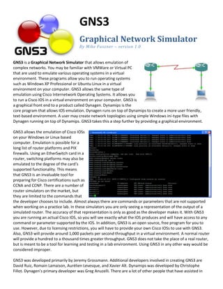
  • 1. GNS3 Graphical Network Simulator By Mike Fuszner – version 1.0 GNS3 is a Graphical Network Simulator that allows emulation of complex networks. You may be familiar with VMWare or Virtual PC that are used to emulate various operating systems in a virtual environment. These programs allow you to run operating systems such as Windows XP Professional or Ubuntu Linux in a virtual environment on your computer. GNS3 allows the same type of emulation using Cisco Internetwork Operating Systems. It allows you to run a Cisco IOS in a virtual environment on your computer. GNS3 is a graphical front end to a product called Dynagen. Dynamips is the core program that allows IOS emulation. Dynagen runs on top of Dynamips to create a more user friendly, text-based environment. A user may create network topologies using simple Windows ini-type files with Dynagen running on top of Dynamips. GNS3 takes this a step further by providing a graphical environment. GNS3 allows the emulation of Cisco IOSs on your Windows or Linux based computer. Emulation is possible for a long list of router platforms and PIX firewalls. Using an EtherSwitch card in a router, switching platforms may also be emulated to the degree of the card’s supported functionality. This means that GNS3 is an invaluable tool for preparing for Cisco certifications such as CCNA and CCNP. There are a number of router simulators on the market, but they are limited to the commands that the developer chooses to include. Almost always there are commands or parameters that are not supported when working on a practice lab. In these simulators you are only seeing a representation of the output of a simulated router. The accuracy of that representation is only as good as the developer makes it. With GNS3 you are running an actual Cisco IOS, so you will see exactly what the IOS produces and will have access to any command or parameter supported by the IOS. In addition, GNS3 is an open source, free program for you to use. However, due to licensing restrictions, you will have to provide your own Cisco IOSs to use with GNS3. Also, GNS3 will provide around 1,000 packets per second throughput in a virtual environment. A normal router will provide a hundred to a thousand times greater throughput. GNS3 does not take the place of a real router, but is meant to be a tool for learning and testing in a lab environment. Using GNS3 in any other way would be considered improper. GNS3 was developed primarily by Jeremy Grossmann. Additional developers involved in creating GNS3 are David Ruiz, Romain Lamaison, Aurélien Levesque, and Xavier Alt. Dynamips was developed by Christophe Fillot. Dynagen’s primary developer was Greg Anuzelli. There are a lot of other people that have assisted in
  • 2. various ways in the development of these products. Development is an ongoing process as each product evolves. This documentation will begin with a Quick Start Guide followed by a more in-depth discussion. Finally, in this introduction, I’d like to list a variety of Web sites that you will find useful: http://www.gns3.net GNS3’s primary Web site http://wiki.gns3.net GNS3’s Wiki site http://www.ipflow.utc.fr/index.php/Cisco_7200_Simulator Dynamips – the actual emulator http://www.ipflow.utc.fr/blog/ Dynamips blog http://dyna-gen.sourceforge.net/ Dynagen http://www.ipflow.utc.fr/bts/ Dynamips/Dynagen bug tracking http://7200emu.hacki.at Hacki’s forum The most useful sites will be www.gns3.net and http://7200emu.hacki.at. The GNS3 site will be specific to GNS3. However, the hacki site is an invaluable forum where you’ll find many how-to’s and be able to interact with other users. I highly recommend that you visit both sites.
  • 3. GNS3 Quick Start Guide for Windows Users This section will take you through the steps to get started with GNS3 in a Windows environment. All of the critical and most important things to know will be covered, but for an in-depth discussion, see later sections of this document. If you use Linux, there is a GNS3 Quick Start Guide for Linux Users in the next section. Step 1: Download GNS3. Use your Web browser to access http://www.gns3.net. Click on the green Download button. The easiest way to install GNS3 in a Windows environment is to use the top file: GNS3-0.5-win32- all-in-one.exe. Click on Mirror 1 or Mirror 2 to begin the download.
  • 4. Click the Save button and then choose a location on your hard drive to save the file. Your download will begin. The file is a little under 10 MB in size and will take less than minute to download on a DSL or cable connection. Dial-up connections will take somewhat longer. Step 2: Install GNS3 Find the file you download and double-click on it to begin installing GNS3. The GNS3 Setup Wizard will begin. Click the Next button. Click the I Agree button to continue.
  • 5. Allow GNS3 to create a Start Menu folder with the default name GNS3 by clicking the Next button. GNS3 depends on several other programs to operate. Those dependencies include WinPCAP, Dynamips, and Pemuwrapper. These components along with GNS3 are all chosen by default for installation, so just click the Next button to continue. A default location is chosen for GNS3. Click the Install button to accept the default location and to begin the actual installation of files. The first dependency for GNS3 is WinPcap. Click the Next button to begin the WinPcap Setup Wizard.
  • 6. Click I Agree to accept the License Agreement for WinPcap. The installation for WinPcap will begin. However, if you have a previous version of WinPcap on your computer, the wizard will ask to remove the older version and will then install the newer version. After WinPcap is installed, the GNS3 Setup Wizard returns to installing GNS3. When the wizard finishes, you may uncheck Show Readme and then click the Finish button. You have now completed the installation of GNS3. Click the Start button, All Programs, GNS3, and then choose GNS3 out of the list of applications installed. You’ll see the main GNS3 window. We’ll discuss its panes in a later step, but first we have to configure the location for a Cisco IOS.
  • 7. Step 3: Defining Cisco IOS files As mentioned earlier, you must provide your own Cisco IOS to use with GNS3 due to licensing issues. GNS3 is meant to be used in a lab environment for testing and learning. Once you have obtained your own copy of a Cisco IOS for one of the supported platforms, you are ready to continue. Current platforms supported include: 1710 2611 2691 1720 2611XM 3620 1721 2620 3640 1750 2620XM 3660 1751 2621 3725 1760 2621XM 3745 2610 2650XM 7200 2610XM 2651XM On the Edit menu, choose IOS image and hypervisors. Under the IOS Images tab, click and then find your Cisco IOS file and click Open. The file will appear as your Image file.
  • 8. Next, click the drop-down arrow next to Platform and choose the platform that corresponds to your IOS file. Now click the drop-down arrow next to Model and choose the model corresponding to your IOS file. For now, we’ll accept the default values that remain. However, there is a very important value called the IDLE PC value that we will want to include. We’ll get to that later. Click the Save button and then the Close button. This will return you to the default GNS3 window. It’s time to create our very first simple topology. But before that, the next section will present a GNS3 Quick Start Guide for Linux Users.
  • 9. GNS3 Quick Start Guide for Linux Users Let’s turn our focus to Linux users now. Our examples will use Ubuntu. Anyone can download Ubuntu from www.ubuntu.com for free – it just may take awhile since it’s a large file. Performance is somewhat better in a Linux environment, but the difference is not significant. First, we’ll install necessary dependencies. Step 1: Install necessary dependencies Open the Synaptic Package Manager. Go to the System menu, then Administration, and finally Synaptic Package Manager. Click the Search button in the toolbar, type python-qt4 in the Search box and click the Search button.
  • 10. When you find python-qt4, click on the white box in front of it, and choose Mark for Installation. Click Mark and the click the Apply button in the toolbar. On the Summary window, click Apply.
  • 11. Step 2: Download GNS3. Use Firefox to access http://www.gns3.net. Click on the green Download button. You may choose any of the source archives for Linux. We will use GNS3-0.5- src.tar.gz. Click on Mirror 1 or Mirror 2 to begin the download. By default, the file will be downloaded to the desktop. Next, right-click on the file on the desktop, GNS3-0.5- scr.tar.gz, and choose Extract Here.
  • 12. You’ll see a new icon on the desktop labeled GNS3-0.5-src. Now we need to download the latest Dynamips binary for Linux. Use Firefox to visit the Dynamips blog Web site at: www.ipflow.utc.fr/blog/ In our example, it is found farther down the page as 0.2.8- RC2 binary for Linux x86 platform. Drag the downloaded file, dynamips-0.2.8-RC2- x86.bin into the GNS3-0.5-src folder.
  • 13. Let’s change the Dynamips permissions to allow execution. Double-click on dynamips-0.2.8-RC2- x86.bin and choose Properties. Click on the Permissions tab, and then click the box next to Execute: Allow executing file as program. Then click Close. Step 3: Configuring GNS3 Double-click the gns3 icon to start the application. Click the Run button. The Setup Wizard begins with a message as shown. Click on the big number 1 to open the Preferences window (actually located under the Edit menu in GNS3).
  • 14. Then click Dynamips in the left-hand pane. Click the ellipses next to Executable path and then click dynamips-0.2.8-RC2-x86.bin and followed by the Open button. When you return to the Preferences screen, click OK. Now you return to the Setup Wizard. Click the big number 2 to open the IOS images and hypervisors window (actually located under the Edit menu in GNS3).
  • 15. Use the ellipses button next to the Image file box to locate an IOS image. As mentioned earlier, you must provide your own Cisco IOS to use with GNS3 due to licensing issues. GNS3 is meant to be used in a lab environment for testing and learning. Once you have obtained your own copy of a Cisco IOS for one of the supported platforms, you are ready to continue. Current platforms supported include: 1710 2611 2691 1720 2611XM 3620 1721 2620 3640 1750 2620XM 3660 1751 2621 3725 1760 2621XM 3745 2610 2650XM 7200 2610XM 2651XM Then click the Save button followed by the Close button. You’ll return again to the Setup Wizard window. Click OK to finish. It’s time now to create our first simple topology. So whether you are Windows user or a Linux user, continue to the next section. We have often used screen shots from Windows when describing GNS3 usage, but the screen shots from Linux would look identical except for the title area.
  • 16. Creating the Simplest Topology We describe how to build a more complex topology later, but for now, let’s just learn how to place one router on the desktop, start it, and console into it. We will then learn how to find an idlepc value for the IOS we are using. This is a very important step. When an IOS is running, it will consume up to 100% of your CPU time. This will cause your computer to become very sluggish and will prevent building more complex topologies. However, if we use an idlepc value, we can reduce CPU usage dramatically. It puts the IOS into a sleep state when it is not in active use and wakes it up only when it is necessary. A more technical explanation will be given later. The GNS3 window is divided into four panes by default. The left-most pane lists the types of nodes available. You will see router icons for the various platforms, a PIX firewall, Ethernet switch, ATM bridge, ATM switch, Frame Relay switch, and Cloud. Other node types may be added as explained later. The right-most pane will provide a topology summary that will be better understood when we built more complex topologies. For now, just know that the pane exists. The middle section contains two panes. The top pane is your work area where a topology may be graphically built. The bottom pane, called the Console, shows Dynagen at work. Dynagen, as you recall, is the text-based front end to Dynamips, the core emulator being used. Learning how to use Dynagen is like learning how to use DOS the first time, so we will not get into that here. However, we will use a very few simple but useful commands in the Dynagen pane. Click on a router icon under Nodes Types corresponding to the IOS platform you are using. In our example, we are using a 7200 platform. You must use a platform for which you defined an IOS. Drag an appropriate router node type over to the workplace pane in the middle and let go. We now have a router ready to configure. Right-click the router and choose Configure.
  • 17. Click on R1 and then the Slots tab. Click the drop-down arrow next to slot0 and choose an adapter that says FE at the end. This will add a FastEthernet adapter to the router. Next, click the drop-down arrow next to slot1 and choose PA-4T+. This will add four serial interfaces to the router. Click OK. (Note: If you do not have these exact adapters, just choose something close.) Right-click the router and choose Start. Right-click the router again and choose Console. A telnet console opens up. (Note: In Windows Vista, the telnet client is not automatically installed as in previous versions of Windows. Click on the Start sphere and choose Control Panel. Click on Programs. Under Programs and Features, click on Turn Windows features on or off. Click next to Telnet Client to place an x in the box. Click OK.) You may need to press Enter once initially in the Console window. When asked “Would you like to enter the initial configuration dialog?”, enter no and press Enter. Wait for the router to settle down at a Router> prompt. You may need to press Enter once or twice to get there.
  • 18. After the router has settled down to a Router> prompt, return to the main GNS3 window. Right-click R0 and choose Idle PC. GNS3 will spend a moment calculating an Idle PC value before presenting the screen to the right. If you click the drop-down arrow, you see a list of possible idlepc values. Potentially better idlepc values are marked with an asterisk. Choose one of the values with an asterick (in our example, we will choose number 4) and click OK. You’ll receive a confirmation that the idlepc value has been applied. If you choose IOS images and hypervisors on the Edit menu, and double- click on the image under the IOS Images tab, you’ll see the new idlepc value displayed under Settings. You may repeat this process to find the value that reduces CPU usage the most. To observe CPU usage in Windows, press Ctrl+ALT+DEL and choose Task Manager. Click on the Performance tab to view CPU usage. In Ubuntu, choose System Monitor under Administration on the System menu. Click the Resources tab. You will observe that without an idlepc value, CPU usage will be at or near 100%, but with an idlepc value, CPU usage will drop to a very low value.
  • 19. Enjoy using your router! You may now return to your telnet window to use your router. You are actually running the Cisco IOS that you chose. All commands supported by the IOS are available. Remember earlier we chose a FastEthernet adapter and a four-port serial adapter. If you issue the show ip interface brief command as shown, you’ll see the designations for these four ports on the router. In our example, they are fa0/0, s1/0, s1/1, s1/2, and s1/3 (in abbreviated form).
  • 20. GNS3 Main Interface Before continuing you may want to take a moment to view the following labeled graphics: Drop-down menu from right-clicking on a router:
  • 21. Building More Complex Topologies Although a single router is useful to get familiar with commands, it would be nice to build more complex topologies. With GNS3 very complex topologies may be built. Just as performance when running virtual machines within VMware or Virtual PC depends on your computer resources, running many router instances will affect the performance of your computer. The faster your CPU and the more RAM that you have, the better. However, idlepc does a lot to help with CPU usage. Ghostios and sparsemem are two additional utilities that will help with RAM usage. Ghostios is enabled by default in GNS3. Sparsemem must be enabled, since it is off by default. These will be discussed in detail in the section on Memory Usage. As an example, with 2 Gigabytes of RAM and a 2.5 GHz processor, you should have no problems running a lab with good performance with a half dozen routers and several workstations. Let’s build the topology shown with three routers. Start GNS3. Drag three routers running an IOS you have configured into the workspace. Right-click each router and choose Configure. Under the Slots tab, include a FastEthernet adapter and PA-4T serial adapter. Now we’re ready to connect the routers together. Click the Add a link button on the toolbar at the top. Choose Manual from the drop-down menu. Your cursor will change to a cross. Click on R0 and select s1/0 – then click on R1 and select s1/0. Click on R1 again and select s1/1 – then click on R2 and select s1/1. Now click the Add a link button again (now it looks like a red Stop sign with an X. After clicking on it, the icon will change back to a connector look. Notice the right-pane call Topology Summary. Your connections are now available for viewing by clicking the plus next to each router. GNS3 gives each router a default name beginning with R. If you would like to change the name, right-click on a router and choose Change the hostname. For this example, we will continue to use the default names. There are four buttons on the toolbar at the top: The first button is the Telnet to all IOS button. The next three buttons are the Start/Resume all IOS, Suspend all IOS, and Stop all IOS. The links are all red. Let’s start the routers by clicking the Start/Resume all IOS button on the toolbar. A box will pop up indicating the routers are being started, and the links will turn green. If we click the Telnet to all IOS button, we may observe the boot-up process of each router. A separate console window will open for each router. Answer No and press Enter for each router at the question “Would you like to enter the initial configuration dialog?”. You may now configure each router. In our example, we will change the hostnames, configure the secret password, enable synchronous logging, assign IP addresses to the interfaces and turn them on, enable RIP version 2, and finally test connectivity by using pings.
  • 22.
  • 23. As you can see, East can ping West which verifies connectivity from end-to-end. You may also see that East has the 10.0.0.0/24 network in its routing table. Now let’s drag three Ethernet switches and place one under each router. Use the Add a link button to add a connection from each router’s Fa0/0 port to port 1 on each switch. Note that the built-in Ethernet switch has 8 ports. They may act as access ports or dot1q trunking ports. By default, they act as access ports. If you right-click a switch and choose configure, you’ll see that you may specify several options. We will use the default values. If you wish to configure more advanced options with switches, then you’ll need to add a router with an NM-16ESW EtherSwitch adapter. These adapters support many more switching functions but not all. We’ll discuss EtherSwitch adapters in a later section. It’s time to add PCs to your topology.
  • 24. Adding PCs to Your Topology There are three possible ways to add a computer to your topology. If you just need to check for connectivity using ping or traceroute, the best way is to use the Virtual PC Simulator. You may also add another router but configure it to act like a PC. Finally, you may use your real PC. Using the Virtual PC Simulator (and the Symbol Library) The Virtual PC Simulator is a program that runs within Windows or Linux. It has limited functionality, but most important, it allows pings and traceroutes. These are the most common testing commands used during CCNA or CCNP training and are often the only commands needed. Using VPCS you will save memory and CPU cycles. If you do not need more functionality in a workstation within your topology, I highly recommend VPCS. The Virtual PC Simulator is a free product available at the following Web site: http://wiki.freecode.com.cn/doku.php?id=wiki:vpcs Extract the archive to your PC, and then in Windows run vpcs.exe. If you are running Linux, right-click the vpcs (not vpcs.exe) and choose Properties. Click on the Permissions tab. Then click on the box next to Execute. Click Close. Now right-click the desktop and choose Create Launcher. Click the down arrow next to Type and choose Application in Terminal. For Name, type VPCS. For Command, you may browse to the vpcs program. For Comment, type Virtual PCs. Click OK. Now just click the VPCS icon on your desktop. It is best to open the Virtual PC Simulator before starting GNS3.
  • 25. For help, just type ? at the prompt. VPCS supports up to nine PCs. Just type a number to switch to another PC. Use the Show command to view a PC’s IP or MAC address. To assign an IP address, subnet mask, and default gateway to a PC, follow this format at the prompt: ip 10.0.0.5 10.0.0.1 24 The above command assigns the PC an IP address of 10.0.0.5 with a /24 subnet mask and a default gateway of 10.0.0.1. To switch to PC2, just type a 2 and press Enter. The program is very easy to use. You’ll find more information at the above Web site. To integrate VPCS into GNS3, we will first make use of the Symbol Library. Choose Symbol Manager on the Edit menu after opening GNS3. Click the computer symbol under Available symbols, then click right arrow button between the windows. This will move the symbol into the Customized nodes column. In the Name box, type computer. Use the drop-down arrow to change the type to Cloud, if necessary. Click the Apply button. Then click OK. In the GNS3 Nodes Types column, you should now see a computer icon. Drag three computers into the workspace, placing one below each switch. Right-click the computer under West, and choose Configure. Click on C0 under Clouds. Click the NIO UDP tab. Type in the following values under Settings: Local port: 30000 Remote host: 127.0.0.1 Remote port: 20000 These settings correspond to VPCS 1. Click the Add button and then OK.
  • 26. Now right-click each of the other computers and choose Configure. Use the following settings: Computer Local port Remote host Remote port C1 30001 127.0.0.1 20001 C2 30002 127.0.0.1 20002 We have just configured each of the computers as clouds that connect with GNS3 through the UDP ports designated. Before we can connect our VPCs to our switches, we’ll need to add a port to each switch. Right-click each switch and choose Configure. Click on the switch (SW0, SW1, or SW2), change Port setting to 2, and click the Add button and then OK. Now click the Add a link button on the Toolbar and choose Manual. Connect port 2 of each switch to its corresponding VPC’s nio_udp port. Click the Add a link red stop sign button to stop adding links. Now configure the VPCs within the VPCS window. Configure IP address, default gateway, and subnet mask (24) for each PC with the values shown in the topology. Here are the commands that you would use: Return to each router’s console window to configure its FastEthernet port. Use the addresses shown in the topology above. Be sure to use no shutdown to turn on the interface. Then add the network to RIP with the router rip command and network command. The routes should show up shortly in the routing tables. Try to ping from West’s computer to East’s computer. This ping should work. A ping from West’s computer to Central’s computer should also work. Using a Router that Acts Like a PC You may also simply add another router to your topology and configure it to act like a PC. This method would use more memory and processor cycles than the previous method, so I would only recommend this method as a secondary choice. Just add a router and enter the following commands: Router(config)# no ip routing Turns off IP routing function Router(config)# interface fa0/0 Switches to FastEthernet interface Router(config-if)# ip address address subnet_mask Assigns IP address and subnet mask to interface Router(config-if)# no shutdown Turns interface on Router(config-if)# exit Returns to global configuration mode Router(config)# ip default-gateway gateway_address Configures the default gateway Router(config)# ip http server Optional – starts http server process Connect the router (acting as a PC) to the rest of your topology.
  • 27. Using your Real PC – Talking to Real Networks One of the interesting things about GNS3 and Dynamips is that you can connect your topology to the real world. For some of your CCNA and CCNP studies you may need to run an actual Web browser or Cisco’s Security Device Manager (SDM) among others. Just connect your topology to your real PC. You could even connect to virtual machines running on your computer inside VMware or Virtual PC. I’ve even set up two copies of Windows XP Professional running inside VMware virtual machines. Then I ran Cisco soft IP Phones that could talk to themselves. You could connect your virtual network to a real network as well. Connecting a virtual topology running within GNS3 and Dynamips to real devices is very exciting, but again, your throughput is going to be limited compared to using real equipment for the entire topology. It only makes sense to use GNS3 and Dynamips in a lab environment and for learning purposes. Any other usage is highly discouraged! Connecting your topology to your real PC is very similar to the process used with the Virtual PC Simulator above. Drag a computer (defined as cloud) into your workspace. Right-click the computer and choose Configure. Click on C0 under Clouds, but choose the NIO Ethernet tab. Administrator rights are required (root account under Linux). For Windows users, click on the box directly beneath Generic Ethernet NIO, and choose the network adapter you wish to use. For Linux users, click on the drop-down box to choose your network adapter (either your real adapter or a loopback adapter). Click the Add button and OK. You will need to configure the IP settings for your computer’s adapter, and then use the Add a link toolbar button to create your connection. You may use your regular network adapter, but I usually create an MS Loopback adapter to connect to. In Windows, use the Add Hardware wizard in Control Panel. Choose “Yes, I have already connected the hardware.” On the next screen, choose Add a new hardware device at the end of the list and click Next. Choose to “Install the hardware manually…” and click Next. Choose Network Adapters in the list and click Next. Choose Microsoft as the manufacturer and then Microsoft Loopback Adapter as the network adapter. Finish the wizard. Then right-click My Network Places and choose Properties. You may wish to rename the new Local Area Connection as MS Loopback Adapter. Also, assign the proper IP settings to the adapter in order to connect to your topology. Linux has a built-in loopback adapter already installed.
  • 28. Using Terminal Programs Like PuTTY or TeraTerm By default, GNS3 uses the telnet application built into Windows or Linux. But if using Windows, you may prefer to use PuTTY or TeraTerm. Both of these terminal emulators are free to download at one of the following Web sites: PuTTY: http://www.chiark.greenend.org.uk/~sgtatham/putty/ TeraTerm: http://hp.vector.co.jp/authors/VA002416/teraterm.html Just download the terminal program you prefer and install it on your computer. Inside GNS3, choose Preferences under the Edit menu. Choose General in the left pane, and the change the Terminal command box to read: For PuTTY: c:puttyputty.exe -telnet %h %p For TeraTerm: c: TTERMPROttssh.exe %h %p /W=%d /T=1 The above commands should be adjusted to point to the location where installed the program. Note that with PuTTY instead of the built-in telnet client, your router name will appear in the title bar of the window. However, my recommendation for Linux users is to use Konsole-KDE4. That is explained below. WinTabber (Multiple tabs for Windows) If you are using a topology that opens several console windows, it becomes a bit of a challenge switching from one device to another. You may consolidate all of these windows into one application where the windows are located under tabs. There are several ways to do this, but the program I like is called WinTabber. It’s another free download at the following site: http://www.wintabber.com/ Note: WinTabber works with Windows 2000/XP/Vista. Since Wintabber is only a Windows program, I recommend Konsole for Linux users.
  • 29. Konsole (Multiple tabs for Linux) If you are using a topology that opens several console windows, it becomes a bit of a challenge switching from one device to another. You may consolidate all of these windows into one application where the windows are located under tabs. For Linux users, I recommend using Konsole, but the version is very important. If you open Konsole and then choose About Konsole under the Help menu, your version should be 2.0 or greater (using KDE 4.0 or greater). It is installed automatically if you are using the KDE4 desktop. If you are using the GNOME desktop (the default in Ubuntu), then you will need to install Konsole using KDE4. Synaptic Package Manager is a Linux tool that finds, installs, or removes software. Let’s use it to find and install Konsole using KDE4. Click on Synaptic Package Manager under Administration on the System menu. Click the Search button and look for konsole-kde4. Right-click konsole-kde4 and choose Mark for installation.
  • 30. Click Apply on the toolbar. Then click the Apply button on the Summary window. The package files are downloaded and installed, and the final changes are applied. Next, open GNS3 and choose Preferences on the Edit menu.
  • 31. Choose General in the left-hand pane of the Preferences window. For Terminal command, use the following: /usr/lib/kde4/bin/konsole --new-tab -p tabtitle=%d -e telnet %h %p >/dev/null 2>&1 & Click OK to commit the change. Now when you console into a device, you’ll have each window in a tab along the bottom. Just click the tab to switch to another window or device.
  • 32. Memory and CPU Usage When you use a topology with multiple devices, issues of memory usage and CPU usage occur. To address the CPU usage issue, an idle-pc value needs to be included. This value is dependent on the IOS version and not the PC. To address memory usage, ghostios and sparsemem must be included. Memory Usage Labs can consume a large amount of real and virtual memory. The “ghostios” and “sparemem” options were added to address both of these issues, respectively. The Ghostios option can significantly reduce the amount of real host RAM needed for labs with multiple routers running the same IOS image. With this feature, instead of each virtual router storing an identical copy of IOS in its virtual RAM, the host will allocate one shared region of memory that they will all utilize. So for example, if you are running 10 routers all with the same IOS image, and that image is 60 MB in size you will save 9*60 = 540 MB of real RAM when running your lab. Ghostios is enabled, by default, in GNS3. The “sparsemem” feature does not conserve real memory, but instead reduces the amount of virtual memory used by your router instances. This can be important, because your OS limits a single process to 2 GB of virtual memory on 32-bit Windows, and 3 GB on 32-bit Linux. Enabling sparsemem only allocates virtual memory on the host that is actually used by the IOS in that router instance, rather than the entire amount of RAM configured. This can allow you to run more instances. Both features rely on mmap, so this must also be enabled. Select Preferences under the Edit menu within GNS3. Check the appropriate boxes to enable these features. CPU Usage We talked about CPU Usage a bit earlier when we learned how to determine idlepc values. Without idlepc values configured, you may have noticed that your system’s CPU was running at 100%. This is because Dynamips, the core emulator running under GNS3, does not know when the virtual router is idle, and when it is performing useful work. The “idlepc” command performs analysis on a running image to determine the most likely points in the code that represent an idle loop in the IOS process. Once applied, Dynamips “sleeps” the virtual router occasionally when this idle loop is executed. This significantly reduces CPU consumption on the host without reducing the virtual router’s capacity to perform real work. IdlePC values are particular to an IOS image. They will be different for different IOS versions, and even for different feature-sets of the same IOS version. However idlepc values are not particular to your host PC, operating system, or to the version of Dynamips that GNS3 is using. It is possible that Dynamips will not be able to find and idlepc value for an image, or that the values it does find do not work. If this happens, try repeating the process again.
  • 33. To determine an idlepc value for a given IOS, start GNS3. Drag only one router set up to use the IOS version you are trying to configure. Right-click the router and choose Start. Then right-click the router and choose Console. You may need to press Enter once initially in the Console window. When asked “Would you like to enter the initial configuration dialog?”, enter no and press Enter. Wait for the router to settle down at a Router> prompt. You may need to press Enter once or twice to get there. After the router has settled down to a Router> prompt, return to the main GNS3 window. Right-click R0 and choose Idle PC. GNS3 will spend a moment calculating an Idle PC value before presenting the screen to the right. If you click the drop-down arrow, you see a list of possible idlepc values. Potentially better idlepc values are marked with an asterisk. Choose one of the values with an asterick (in our example, we will choose number 4) and click OK. You’ll receive a confirmation that the idlepc value has been applied. If you choose IOS images and hypervisors on the Edit menu, and double-click on the image under the IOS Images tab, you’ll see the new idlepc value displayed under Settings. When searching for the best idlepc value, it is a good idea to monitor your CPU usage. To observe CPU usage in Windows, press Ctrl+ALT+DEL and choose Task Manager. Click on the Performance tab to view CPU usage. In Ubuntu, choose System Monitor under Administration on the System menu. You will observe that without an idlepc value, CPU usage will be at or near 100%, but with an idlepc value, CPU usage will drop to a very low value. Experiment with various idlepc values to determine which one works best at reducing CPU usage.
  • 34. I’m tired of those ###### across my screen! Take a look at the ##### across the screen in the graphic to the right. Every time you boot up your router you’ve seen these go across the screen. Many of the Cisco IOSs are compressed. When you see the ####### going across the screen, the IOS is uncompressing itself. You can save time if you uncompress the image now, and then load the uncompressed image when you start your routers. I would recommend that you uncompress all of your IOS images that you plan to use with GNS3. This will significantly speed up your start up time. As a side note, 2600 series images should be uncompressed before using them. If you do not, they are more likely to crash on you. To uncompress an IOS image in Windows, use a product such as UltimateZIP. You may download it from here: http://www.ultimatezip.com/ Download and install UltimateZIP. Then just right-click on an IOS compressed image, and choose Extract to here. To uncompress a file in Linux, just right-click the file and choose Extract Here. Linux has a built-in extracter. Afterwards rename the extracted file with the same filename as the original except with an extension of image instead of bin. This will help you keep track of which image is uncompressed. Then within GNS3 choose IOS images and hypervisors under the Edit menu. Choose the uncompressed version of your IOS when you choose an Image file under Settings. Frame Relay and ATM Devices An integrated Frame Relay switch is provided by GNS3. It is actually part of Dynamips. Just drag the Frame Relay switch from Nodes Types into the workspace. Right-click on the Frame Relay switch and choose Configure. Now you may assign your DLCIs at the source and destination – creating a frame relay map between the two. In our example, local DLCI 102 on port 1 is mapped to DLCI 201 on port 2. You cannot start, stop, suspend, or resume a frame relay switch. ATM switches are configured similarly.
  • 35. Ethernet Switch Devices GNS3 with Dynamips help integrates an Ethernet switch that supports VLANs with 802.1q trunking. Trunk ports trunk all VLANs known to the switch – no VLAN pruning here. It is just a basic virtual switch with limited functionality that provides the very basics you’d want in a switch. If you drag an Ethernet switch onto the workspace, right-click it and choose Configure, you’ll see the options you may set. By default, there are 8 ports in VLAN 1 configured as access ports. However, you may in theory have up to 10,000 ports and up to 10,000 VLANs. You are limited to either access ports or dot1q trunking ports. You may connect the switch to the real world through a cloud device. The Console window in GNS3 may be used to show and clear the MAC address tables using the following commands: show mac switch_name clear mac switch_name If want greater functionality that the virtual Ethernet switch provides that is integrated into GNS3, then you’ll need to add a router with an EtherSwitch card. EtherSwitch Cards You can buy an EtherSwitch card that may be inserted into a router. The card will function similar to a switch. In GNS3 you may also insert an EtherSwitch card into a router slot. The 7200 series routers do not support this adapter but many of the router platforms available in GNS3 do. The EtherSwitch card that is supported is the NM-16ESW. Here is a list of some of the features supported by the NM-16ESW card: Layer 2 Ethernet Spanning Tree Protocol Storm-Control interfaces Cisco Discovery Protocol Port Security Switch Virtual Interfaces Switched Port Analyzer Stacking (SVI) (SPAN) Flow Control VLAN Trunk Protocol Quality of Service EtherChannel IP Multicast Support Not all commands that exist on an actual switch are supported by the NM-16ESW card, but as you can see, using an EtherSwitch card gives you a lot more features than the integrated virtual switch. If you wish to use this card, I recommend that you download documentation from Cisco’s Web site about the module. Only vlan database mode is possible (not the newer global configuration mode) and the show vlan command is show vlan-switch, for example. To use the card, just add a router and include the NM-16ESW adapter.
  • 36. Packet Capture GNS3 along with Dynamips can capture packets on virtual Ethernet or serial interfaces. It will write the captured output to a libpcap file that may be viewed using WireShark. WireShark may be downloaded from the following Web site: http://www.wireshark.org Suppose we want to capture packets passing through the FastEthernet interface on West (f0/0). Right-click somewhere along the line representing the link between West and Central. Choose Capture. The drop-down arrow will allow you to choose which interface to monitor (West f0/0 or Central f0/0). WireShark will automatically start, provided it has been configured under the Preferences window. If we wanted capture packets on the serial link between Central and East, we would also have to choose the encapsulation type. Choices will be HDLC or PPP. If you are using a Frame Relay Switch, you’ll have the FR encapsulation type as an option. Now let’s generate some traffic to test our capture. Ping East from West. Then let’s refresh the WireShark window by pressing Ctrl+R. Scroll down to see the ICMP request and reply packets as a result of the ping. Packets are being captured whether we refresh the window or not.
  • 37. Let’s back up and talk about the preferences for capturing packets. Choose Preferences from the Edit menu in GNS3. Then click on Capture in the left pane. Now you may specify the working directory for capture files, the command to use to start WireShark, and whether to automatically start WireShark when you choose to capture. Saving and Loading Topologies GNS3 will save and load your network topologies using a Dynagen text format called a NET file. Just choose Save or Save As on the file menu. You may also use the buttons on the toolbar. This does not save your router configurations. It just saves your topology drawing, connections, settings, and so forth. If you would like save just the topology drawing as a graphic file, choose Export on the File menu. If you would like to save your router configurations, click the Extract all startup-configs button on the toolbar. You may then paste these configurations back into your routers at a later time. There are other ways to accomplish the same thing. In the Console window, type export /all or export followed by a device name to export the configuration(s). You may then type import /all or import followed by a device name to import the configurations back into your routers. You may use the push /all or save /all commands in order to save the device configurations inside the NET file. When the NET file is opened in GNS3, everything (including router configurations) will be loaded. You must save your configurations within each router before using these commands (write or copy run start). Note: GNS3 will handle a few things differently than Dynagen in NET files. Settings for ram, rom, nvram and the like are recorded in device subsections – not a model section. GNS3 records idle-pc and IOS filenames in device subsections. However, if you select Default image for this chassis under the IOS Images tab in the IOS images and hypervisors window under the Edit menu, a model subsection will be created. Saved NET files may be loaded into Dynagen or GNS3.
  • 38. Client/Server and Multi-Server Mode The Dynamips hypervisor mode used by GNS3 uses a TCP/IP communications channel. This means that GNS3 may run on one machine, while the Dynamips emulator may run on a different machine. Choose IOS images and hypervisor on the Edit menu in GNS3. Under the Hypervisors tab, manually specify a hypervisor. Here we recorded a new hypervisor which will listen on port 7211 on the “remote_host” machine. You can also specify the fully qualified path to the working directory where the hypervisor will store all of its generated files on the Dynamips host. Be sure to use the correct directory separation character for the platform (here back slashes for a Windows system). You must use a DNS name or an IP address in the Host text box. Base UDP is the base port for UDP NIOs that Dynamips uses to make the connections between your nodes. Dynamips will use a UDP port for each end of a link. For example, six UDP ports are used for a full meshed lab of 3 routers and a base udp of 10000. Here is an output of the netstat command that shows you the connections between the nodes and the UDP port picked up by Dynamips: udp 0 0 localhost:10000 localhost:10001 ESTABLISHED udp 0 0 localhost:10001 localhost:10000 ESTABLISHED udp 0 0 localhost:10002 localhost:10003 ESTABLISHED udp 0 0 localhost:10003 localhost:10002 ESTABLISHED udp 0 0 localhost:10004 localhost:10005 ESTABLISHED udp 0 0 localhost:10005 localhost:10004 ESTABLISHED (NIO stands for Network I/O. These are the network interfaces coded in Dynamips that allow it to communicate in many ways, such as Ethernet, UDP, or TCP.) Now let's imagine you want to run two connected IOS instances which are separately created on 2 different hypervisors on the same host, and you choose the same UDP base for the hypervisors. Each hypervisor will try to take the same UDP port (10000 in the previous example) for each end of the connection and, of course, this will collide because Dynamips thinks they are different servers and therefore those UDP ports are safe to re-use. Base console is the TCP base port that the hypervisor will use when you open a console on an IOS. This value shouldn't collide because GNS3 uses the following formula to affect a console port to each router: base port + router id (which is unique). So it is safe to use the same value for every hypervisor. Once your hypervisors are recorded, you can bind them to your IOS images. Select your image, uncheck the Use the hypervisor manager option, and then choose your hypervisor in the list. You may choose more than one hypervisor by holding the Ctrl key down. GNS3 will automatically load balance based on memory consumption. Now every router that is configured with this IOS image is able to communicate with the hypervisor(s).
  • 39. Note: be sure that any host-based firewalls running on all your Dynamips servers (for example, XP SP2’s firewall) are permitting the necessary traffic. This includes the Dynamips server port (defaults to TCP 7200), the console ports (e.g. TCP 2000, 2001, …) and the ports used by the NIO connections between interfaces, which start at UDP 10000 and work up from there. Console Window - DynaGen Commands If you type a ? in the Console window, you’ll see the list of commands supported. The table below will summarize the meaning of each command. Generally, you do not need to understand these commands, but they can extend your usage of GNS3. Console Window Commands Command Examples Description capture capture West f0/0 west.cap Begins a capture of all packets in and out of an no capture West f0/0 interface. The first capture is for an Ethernet interface. If capture a serial interface, the encapsulation must be capture East s0/0 East.cap hdlc specified: hdlc, ppp, fr (frame-relay). no capture East s0/0 View results in WireShark. confreg confreg /all 0x2102 Sets the configuration register value confreg R1 0x2102 cpuinfo cpuinfo /all Show cpu info for router cpuinfo R1 export export /all “c:temp” Saves router config files individually in directory export R1 “c:temp” hist hist Prints a list of commands that have been used list list Lists all devices py py <python statement> Executes Python commands. For example, py print namespace.devices save save /all Stores router configs in the NET file save R1 show show mac switch_name Shows mac address table of Ethernet switch show device Shows detailed information about devices in lab show start Shows startup lab configuration show run Shows running configuration of current lab show run R1 Shows running configuration of router suspend suspend /all Suspends router suspend R1 clear clear mac switch_name Clears mac address table of Ethernet switch console console /all Connect to the console port of a router console R1 end end Exits from the console filter filter R1 s1/0 freq_drop in 50 Drops 1 out of every 50 packets inbound to R1 on s1/0 filter R1 s1/0 none in Removes all inbound filters from R1 on s1/0 idlepc idlepc get R1 Get a list of possible idlepc values for router R1 idlepc show R1 Show the previously determined idlepc value for R1
  • 40. idlepc set R1 0x12345 Manually set R1’s idlepc value to 0x12345 idlepc copy R1 /all Set the same idlepc as on R1 for same IOS idlepc save R1 Saves idlepc value for R1 idlepc save R1 default Saves R1’s idlepc value to defaults section of NET file idlepc save R1 db Save R1’s idlepc to the idlepc database idlepc idlemax R1 1500 Set the idlemax parameter for R1 idlepc idlesleep R1 30 Set the idlesleep parameter for R1 idlepc showdrift R1 Display the drift of idlepc on R1 no no command Negates a command reload reload /all Reloads a router reload R1 send send bender hypervisor version Sends a raw hypervisor command to a Dynamips server. Example: sends hypervisor version command to host named bender start start /all 30 Starts a router. When using /all, you may specify a start R pause in seconds between starting devices. telnet telnet /all Telnets to the console port. Same as console telnet R1 command. conf conf localhost Switch into configuration mode of the specific hypervisor copy copy run start Copy running topology into startup topology exit exit Exits from console help help command Gives help for a command import import /all “c:temp” Imports configuration files from directory import R1 “c:temp” push push /all Pushes router configs from NET file into nvram push R1 resume resume /all Resumes a specific router after a suspend resume R1 shell shell Passes command to a system shell when line begins with ! stop stop /all Stops a router stop R1 ver ver Print the Dynagen version and credits Using a Newer Version of Dynamips with GNS3 The version of Dynamips included with the Windows GNS3 installer requires Windows XP SP2. Download the Windows binaries from the Dynamips site (http://www.ipflow.utc.fr/blog/). For Windows XP / 2003 use “dynamipswxp.exe”. For Windows 2000, use the file “dynamips-w2000.exe” instead. Then copy both your executable and “cygwin1.dll” to “C:Program FilesGNS3Dynamips”, replacing the existing files. With Linux you download the latest Dynamips version as part of the install process, so this is not an issue.
  • 41. PIX Firewall Emulation GNS3 is also capable of emulating PIX firewalls. Once again, you’ll need to provide your own PIX image. If you want to run more than a restricted license, you’ll also need to have a valid serial number and activation keys. First, go to Preferences on the Edit menu in GNS3. Click on PEMU in the left pane. The default path to the Pemuwrapper should be fine. You may want to specify a different working directory. Also, be sure to check Enable Pemu Manger and Use Pemu Manager when importing. Under Defaults PIX settings, use the button next to PIX image to specify the location of your PIX operating system image. You may use the default Key and Serial number, if necessary. This will provide a restricted license with limited features. You will need a valid serial number and activation keys to access additional features. The graphic on the left is a restricted image. Failover, VPN-DES, and VPN-3DES-AES are disabled. You are also limited to 6 physical interfaces and 25 VLANs. The graphic on the right is unrestricted. With an unrestricted license, these features are enabled along with support for additional interfaces and VLANs. If you have a serial number and valid activation keys, you may move from a restricted license to an unrestricted license. Type in the activation keys separated by commas with no spaces. Use all lower case. Be sure your serial number is converted to hexadecimal. It is usually in decimal in a show version command. Use a calculator to convert from decimal to hexadecimal if necessary. Click OK to return to the GNS3 main interface. Drag a PIX firewall icon from the Nodes Types pane into the workspace. Right-click on FW1 and choose Configure.
  • 42. Click on FW1. Once again, choose a PIX image and type in your Key and Serial number (unless you plan to use the restricted license). Click OK to return the main GNS3 interface. Right-click FW1 and choose Start. Right-click FW1 and choose Console. Once you console into your PIX firewall, issue a show version command. If the activation keys do not show up properly, then issue the following command from privileged mode (enable mode): Pixfirewall# activation-key 0x12345678 0x12345678 0x12345678 0x12345678 The command is issued on one line with spaces between the activation keys. Use valid keys. Save the configuration using either the write command or copy run start. Stop the device and restart it. Congratulations! Your PIX firewall is up and running. Interfaces on the PIX are Ethernet interfaces. To connect to other devices, you’ll need to use either Ethernet or FastEthernet interfaces. You may not connect to a serial interface. You may connect to other PIX firewalls, routers, and switches. You may not connect to a cloud. Consequently, to connect to your real PC or to a Virtual PC, you’ll need to connect from the PIX to a switch, and then from the switch to your PC. Sometimes when you console into your PIX, you will see that when you hit Enter after a command, a second line is added each time. Your PIX is set to echo commands. Similar to when you write a batch file and use the echo off command, we need to turn echo off inside our console session. Here is the procedure:
  • 43. Hold down your Control key as press the right bracket key (Ctrl+]). This puts you into a Microsoft Telnet window. Now type unset crlf and press Enter. Press Enter again to return to the PIX window. CPU Usage – BES and CPULimit Just as with routers, CPU usage is an issue when emulating PIX firewalls on your computer. You will note that your CPU usage is most likely 100%. There are no idle-pc values available for PIX firewalls at this time. Instead, you may use third- party software to control your CPU usage. There are a variety of products on the market. The one that I use for Windows is called BES and is a free download at the following Web site: http://mion.faireal.net/BES/ Complete documentation is available on the Web site along with the program download. Once you start your PIX firewall, start BES. Click the Target button. Choose the pemu.exe process and click the Limit this button. A confirmation screen will appear:
  • 44. Click the Control button to control how much CPU limiting will be used. I’ve set mine to reduce CPU usage by 50%. If you are running multiple firewalls, you will want to limit each one. This program may also limit other processes running on your Windows computer. For Linux, use cpulimit. You may learn more about cpulimit at the following Web site: http://cpulimit.sf.net or http://cpulimit.sourceforge.net Synaptic Package Manager is tool in Linux that finds, installs, and removes software. Let’s use it to find and install cpulimit. Click on Synaptic Package Manager under Administration on the System menu.
  • 45. Click the Search button and type cpulimit in the Search field in the Find window. Right-click cpulimit and choose Mark for Installation. Then click the Apply button in the toolbar. Click the Apply button at the bottom of the Summary window. The changes are applied and the software is installed. Click the Close button to finish the installation.
  • 46. To run cpulimit, press F2 while holding the ALT key down (ALT+F2) in Linux to open a Run Application box. Type the following in the box: cpulimit –e pemu –l 40 This will limit the application pemu to 40% CPU usage. You may type cpulimit –h to see an explanation of the command syntax: Usage: cpulimit TARGET [OPTIONS...] TARGET must be exactly one of these: -p, --pid=N pid of the process -e, --exe=FILE name of the executable program file -P, --path=PATH absolute path name of the executable program file OPTIONS -l, --limit=N percentage of cpu allowed from 0 to 100 (mandatory) -v, --verbose show control statistics -z, --lazy exit if there is no suitable target process, or if it dies -h, --help display this help and exit The following shows the result of running a PIX Firewall (pemu) in GNS3 without CPU control on the left, and then the CPU levels after using cpulimit at 40%:
  • 47. Symbol Library GNS3 provides a variety of symbols, or icons, which may be used in creating topologies. We see some of them in the Nodes Types pane on the left of the main interface. If you choose Symbol Manager on the Edit menu, you’ll see some additional symbols in the Available symbols pane. To add one of these symbols, select it in the Available symbols pane on the left, and click the arrow button in the middle. This will transfer a copy of the symbol to the Customized nodes pane on the right. You may then type a new name for the symbol in the Name field at the top. In addition, you may specify the type of symbol by using the drop-down arrow next to Type. For example, I’ve added a computer as a cloud in the example. What if you’d like to add some symbols of your own? First, you must create your own Symbol Library. Then simply specify the path to your Symbol Library and click the Add button. To create your custom-made symbols library, gather together all of the symbols you’d like to include in your library. All symbols must be converted to scalable vector graphics (svg). If you have images in formats such as jpg or bmp, you’ll need to convert them. An open source product you may download and install for free to accomplish this is Inkscape. You’ll find it at the following Web site: http://www.inkscape.org/ Download Inkscape and install it. Open Inkscape and then open your jpg or bmp file. Then use Save As on the File menu. Give your filename an extension of svg and use the drop-down arrow to choose Plain SVG (*.svg). Convert all of your symbols to svg files before you continue. By the way, I would size your images to around 70x70 so they fit in size-wise with the other symbols. As an example, I am going to add a firewall, IP Phone, and laptop as new symbols in a custom symbols library. I’ve used Inkscape to convert my jpg files to svg files. Next, create an XML file with the extension qrc. Every entry has an alias that is the name of the symbol as it will appear in GNS3. I will use the aliases “Firewall”, “IP Phone”, and “Laptop”. The path on my computer where I have placed these images is d:symbols. You may use the full path or relative path. Here is the file that I will call mike.qrc: <!DOCTYPE RCC><RCC version="1.0"> <qresource> <file alias=’Firewall.svg’>d:symbolsfirewall.svg</file> <file alias=’IP Phone.svg’>d:symbolsipphone.svg</file> <file alias=’Laptop.svg’>d:symbolslaptop.svg</file> </qresource> </RCC>
  • 48. Note that my aliases are enclosed in quotes, and that it is acceptable to use spaces. You may create this file in any text editor, such as Notepad. Save it with a qrc extension (be sure there isn’t a hidden txt extension at the end). A qrc file is a resource collection file. My file will be called mike.qrc. Now you need to compile your library using the Qt Resource Compiler (rcc). RCC is included in the Qt application framework that you may download from the Internet. Or you may download the Windows version from GNS3 by pointing your browser to: http://www.gns3.net/files/rcc.exe Rcc.exe will also need mingwm10.dll to work. If you install Qt, this file will be included. If you just download rcc.exe from GNS3, then you’ll need to grab a copy of mingwm10.dll from the Internet. One source to download the file from is: http://www.dll-files.com/dllindex/dll-files.shtml?mingwm10 Copy rcc.exe and mingwm10.dll to the same directory as your qrc file created above. Then open a command prompt or terminal window and traverse to your symbols directory. Now it’s time to compile your custom symbols library for use in GNS3. Use the following command, substituting your filenames as necessary: rcc mike.qrc -compress 9 -binary -o mike.rcc Now you should have your custom symbols library called mike.rcc (in our example). The difficult part is finished! Return to GNS3. Choose Symbol Manger under the Edit menu. Click next to library path and choose your new custom symbol library (mike.rcc in our example). Then click the Add button. Your library is now added and available. Resources I hope this documentation is helpful. But don’t stop here. I highly recommend that you visit the GNS3 Web site at www.gns3.net where video demonstrations are available. Also, one of the most useful sites as you prepare for certifications is the Dynamips forum at http://7200emu.hacki.at.