Tre be civil [compatibility mode]
•
0 gostou•1,262 visualizações

this will help to get all the concept of the transportation engineering of BE civil of college

Recomendados
Mais conteúdo relacionado
Mais procurados
Destaque
Semelhante a Tre be civil [compatibility mode]
Semelhante a Tre be civil [compatibility mode] (20)
Mais de Rahul
Mais de Rahul (20)
Último
Último (20)
Tre be civil [compatibility mode]
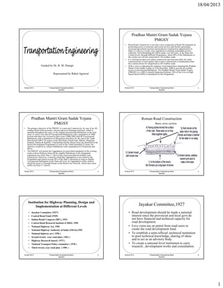
- 1. 18/04/2013 Pradhan Mantri Gram Sadak Yojana PMGSY • Rural Road Connectivity is not only a key component of Rural Development by promoting access to economic and social services and thereby generating increased agricultural incomes and productive employment opportunities in India, it is also as a result, a key ingredient in ensuring sustainable poverty reduction. Notwithstanding the efforts made, over the years, at the State and Central levels, through different Programmes, about 40% of the Habitations in the country are still not connected by All-weather roads. • It is well known that even where connectivity has been provided, the roads y p , constructed are of such quality (due to poor construction or maintenance) that they cannot always be categorized as All-weather roads. Guided by Dr. R. M. Damgir • With a view to redressing the situation, Government have launched the Pradhan Mantri Gram Sadak Yojana on 25th December, 2000 to provide all-weather access to unconnected habitations. The Pradhan Mantri Gram Sadak Yojana (PMGSY) is a 100% Centrally Sponsored Scheme. 50% of the Cess on High Represented by Rahul Agrawal Speed Diesel (HSD) is earmarked for this Programme. 18 April 2013 Transportation Engineering Rahul 1 18 April 2013 Transportation Engineering Rahul 2 Agrawal Agrawal Pradhan Mantri Gram Sadak Yojana Roman Road Construction PMGSY Basic cross section • The primary objective of the PMGSY is to provide Connectivity, by way of an All- weather Road (with necessary culverts and cross-drainage structures, which is operable throughout the year), to the eligible unconnected Habitations in the rural areas, in such a way that all Unconnected Habitations with a population of 1000 persons and above are covered in three years (2000-2003) and all Unconnected Habitations with a population of 500 persons and above by the end of the Tenth Plan Period (2007). In respect of the Hill States (North-East, Sikkim, Himachal Pradesh, Jammu & Kashmir, Uttaranchal) and the Desert Areas (as identified in the Desert D l D Development P Programme) as well as the Tribal (Schedule V) areas, the ) ll h T ib l (S h d l h objective would be to connect Habitations with a population of 250 persons and above. • The PMGSY will permit the Upgradation (to prescribed standards) of the existing roads in those Districts where all the eligible Habitations of the designated population size (refer Para 2.1 above) have been provided all-weather road connectivity. However, it must be noted that Upgradation is not central to the Programme and cannot exceed 20% of the State’s allocation as long as eligible Unconnected Habitations in the State still exist. In Upgradation works, priority should be given to Through Routes of the Rural Core Network, which carry more traffic (see Para 3.7 below) 18 April 2013 Transportation Engineering Rahul 3 18 April 2013 Transportation Engineering Rahul 4 Agrawal Agrawal Institution for Highway Planning, Design and Implementation at Different Levels Jayakar Committee,1927 • Jayakar Committee (1927) • Road development should be made a national • Central Road Fund (1929) interest since the provincial and local govt do • Indian Roads Congress (IRC), 1934 not have financial and technical capacity for • Central Road Research Institute (CRRI), 1950 road development. • National Highway Act, 1956 g y , • Levy extra tax on p y petrol from road users to • National Highway Authority of India (NHAI),1995 create the road development fund. • National highway act ( 1956 ) • To establish a semi-official ,technical institution • Second twenty year road plan ( 1961 ) to pool technical knowledge, sharing of ideas • Highway Research board ( 1973 ) and to act as an advisory body. • National Transport Policy committee ( 1978 ) • To create a national level institution to carry • Third twenty year road plan ( 1981 ) research , development works and consultation. 18 April 2013 Transportation Engineering Rahul 5 18 April 2013 Transportation Engineering Rahul 6 Agrawal Agrawal 1
- 2. 18/04/2013 Classification of Highways Depending on weather • All weather roads • Fair weather roads Depending the type of Carriage way • Paved roads • Unpaved roads Depending upon the pavement surface • Surfaced roads • Un surfaced roads Based on the Traffic Volume • Heavy • Medium • Light Based on Load or Tonnage • Class 1 or Class 2 etc or Class A , B etc Tonnes per day Based on location and function ( Nagpur road plan ) NH, SH, MDR, ODR & VR 18 April 2013 Transportation Engineering Rahul 7 18 April 2013 Transportation Engineering Rahul 8 Agrawal Agrawal Road Patterns Factors Influencing Highway Alignment • Rectangular or Block patterns Requirements: • Radial or Star block pattern Short • Radial or Star Circular pattern Easy • Radial or Star grid pattern Safe Economical • Hexagonal Pattern Factors controlling alignment : • Minimum travel Pattern 1) Obligatory points A. Obligatory points through which alignment is to pass ( bridge site, intermediate Classification of Roadways town , Mountain pass e c ow ou p ss etc B. Obligatory points through which alignment should not pass. 2) Traffic • Expressways 200 Km 3) Geometric design 4) Economics • National Highways 70,548 Km 5) Other considerations • State Highways 1,31,899 Km Additional care in hill roads • Major District Roads 4,67,763 Km Stability Drainage • Rural and Other Roads 26,50,000 Km Geometric standards of hill roads Resisting length 18 April 2013 Transportation Engineering Rahul 9 18 April 2013 Transportation Engineering Rahul 10 Agrawal Agrawal Steps in New Highways Project Works Necessity of Re-alignment • Map Study (available topographic map) • Improvement of horizontal alignment design elements such as radius, • Reconnaissance Survey (identification of soil & on spot site inspection) super elevation, transition curve, clearance on inner side of the curve • Preliminary Survey (alternate alignment, comparison of alternate route • Improvement of vertical alignment design elements like steep gradients, & economic analysis) changes in summit curve to increase sight distance, correction of • Location of Final Alignment (transfer of alignment, circular curve & undesirable undulations like humps and dips etc transition curve & super elevation) • Raising level of portion of road which is subjected to flooding, • Detailed Survey (Earth work quantities & other construction materials) submergence or water logging during monsoons • Materials Survey (their collection & testing) • Reconstruction of weak & narrow bridges & culverts & changes in R i f k b id l h i water way at locations slightly away from existing site • Design (embankment & cut slopes, bridges & pavement layers) • Construction of over bridges or under bridges at suitable locations • Earth Work ( highway cutting & drainage system) across a railway line in place of level crossing or another roads to • Pavement Construction (preparation of sub grade, sub base & surface provide grade separate inter section course) • Construction of bypass to avoid the road running through a town or city • Construction Control (quality control tests during different stages) • Defence requirements 18 April 2013 Transportation Engineering Rahul 11 18 April 2013 Transportation Engineering Rahul 12 Agrawal Agrawal 2
- 3. 18/04/2013 Alignment for hill roads Cross Slope or Camber • Minimum hair pin bends. • Bends should be located on stable and flat slopes. • It is the slope provided to the road surface in the transverse direction to drain off the rain water from the road surface. Drainage and quick disposal of water from pavements surface by providing cross slope is • Cross section for hair pin bends should be at intervals of 20-25m. considered important because 15 m on either side of centre line in straight alignment – To prevent entry of surface water into the sub grade soil through pavement, stability & life of • Avoid bends in valleys. pavement get affected if water enters in the sub grade and the soil gets soaked. • Survey for a width of ; 30m on sharp curves. – To prevent entry of water into the bitumen layer and results in deterioration of pavement layers. • Shape of Camber Geometric Design – Parabolic shape – Straight line camber • Elements of design: – Combination of straight and parabolic shape – Sight distance • The length of road ahead visible to drivers Class of road Width of carriage way – Stopping sight distance Single lane 3.75m – Passing sight distance – Horizontal alignment Two lanes, without raised Krebs 7.0m • Super elevation rates (0.1 for rural areas, 0.06 for urban) Two lanes, with raised Krebs 7.5m • Minimum radius Intermediate carriage way 5.5m – Vertical alignment – Pavement design Multi lane pavements 3.5m per lane – Intersection and crossing design 18 April 2013 Transportation Engineering Rahul 13 18 April 2013 Transportation Engineering Rahul 14 Agrawal Agrawal Sight Distance PIEV Theory • Sight distance available from a point is the actual distance along the road • According to this theory the total reaction time of the driver is split into four surface, which driver from specific height above the carriage way has visibility of the stationary or moving object. parts viz. time by the driver for – Perception • Length of road visible ahead the driver at any instance. • It is time required for the sensation received by the eyes or ears to be transmitted to the • Sight distance are of brain through nervous system & spinal cord. – Stopping or absolute minimum sight distance – Intellection – Safe over taking or passing sight distance • It is time required for understanding the situation – Safe sight distance for entering into uncontrolled intersections – Emotion Stopping Sight Distance • It is time elapsed during emotional sensations and disturbance such as fear, anger or fear – Minimum sight distance available on highway at any spot should be of other feelings. sufficient to length to stop vehicle traveling at design speed, safely without – Volition collision with any other obstruction. • It is time taken for final action. I E – Depends on factor • Total reaction time of driver • Speed of vehicle • Efficiency of brakes • Frictional resistance between road and tyre P V • Gradient of the road Reflex Action 18 April 2013 Transportation Engineering Rahul 15 18 April 2013 Transportation Engineering Rahul 16 Agrawal Agrawal Analysis of Stopping Sight Distance Analysis of Overtaking Sight Distance 1. It is sum of 1. The minimum distance open to the vision of the driver of vehicle intending – Lag distance (distance traveled by vehicle during total reaction time) to overtake of slow vehicle ahead with the safety against traffic of opposite – Braking distance (distance traveled by vehicle after application of brakes) direction is known as Min. OSD or Safe OSD 2. Ld = v t meters 2. Factor for min. OSD 3. Bd = (V.V) / (2gf) meters 1. Overtaking speed of vehicle 2. Overtaken speed of vehicle 3. Speed of Vehicle coming from opposite side 4. SSD = Ld + Bd 4. 4 Skill and reaction time of driver d ti ti fd i = (v t ) + {(v v) / (2gf)} meters 5. Rate of acceleration of overtaking vehicle = (0.278 v t ) + {(v v) / (254 f)} kmph 6. Gradient of road V = speed of vehicles 3. (Justo Khanna Page no. 96) F = design coefficient of friction 0.4 to 0.35 OSD = 0.28 Vb t + 0.28 Vb T + 2s+ 0.28 V T G = acceleration due to gravity = 9.8 m/sec2 Vb = speed of over taking vehicle kmph T = reaction time of driver = 2secs V = speed of overtaking vehicle or design speed kmph T = (14.4 s / A)^0.5 and Spacing = s = (0.2 Vb + 6 ) 18 April 2013 Transportation Engineering Rahul 17 18 April 2013 Transportation Engineering Rahul 18 Agrawal Agrawal 3
- 4. 18/04/2013 Traffic Engineering PCU Passenger Car Unit 1. Traffic characteristics 1. Different class of vehicles such as cars, vans, buses, trucks, auto rickshaw, 1. Road user characteristics motor cycles, pedal cycles, bullock carts, etc are found to use common 1. Physical characteristics roadway facilities without segregation on most of the roads in developing 2. Mental characteristics countries like India. 3. Environmental factors 2. The flow of traffic with unrestrained mixing of different vehicle classes on 2. Vehicular characteristics the roadways forms the heterogeneous traffic flow or mixed traffic flow. 1. Static characteristic : Vehicle Dimension, Weight, Speed & Power of vehicle 3. Different vehicle have different dimension like speed, length, acceleration.. 2. Braking characteristic and apart this it has different driver behavior.. behavior 2. Traffic studies and analysis 4. Common practice of considering the passenger car as the standard vehicle 1. Traffic volume studies unit to covert the other vehicle classes and this unit is called as PCU 2. Origin and destination study 5. PCU/lane or PCU/ hour or PCU/ kilometer length of lane.. 3. Parking study 3. Traffic operation-control and regulation 4. Planning and analysis 5. Geometric design 6. Administration and management 18 April 2013 Transportation Engineering Rahul 19 18 April 2013 Transportation Engineering Rahul 20 Agrawal Agrawal Regulatory signs Traffic Signals 1. Regulatory or mandatory sign are meant to inform the road users of certain laws, 1. At intersection where there are a large number of crossing and right turn regulations and prohibitions; the violation of these signs is legal offence. traffic, there is possibility of several accidents as there can’t be orderly 2. Signs are classified as movements. 1. Stop and Give-way sign 2. Traffic signals are control devices which could alternately direct traffic to 2. Prohibitory sign stop and proceed at intersections using Red, Yellow and Green. 3. No parking and no stopping sign 4. Speed limit and vehicle control sign 3. Advantages 5. Restriction ends sign 1. Smooth movements and crossings 6. 6 Compulsory direction control and other sign C l di i l d h i 2. 2 Reduce accidents R d id 3. Informative signs 3. Safety 1. This sign are used to guide road users along routes, inform them of destination and 4. Control speed distance and provide with information to make travel easier, safe and pleasant. 2. Direction and place identification signs 4. Disadvantages 3. Facility information signs 1. Rear end collisions may increase 4. Other useful information signs 2. Improper design and location of signal may lead to violation of control systems 5. Parking signs 3. Failure of signal due to electric power. 6. Flood gauge 18 April 2013 Transportation Engineering Rahul 21 18 April 2013 Transportation Engineering Rahul 22 Agrawal Agrawal Highway Materials Direct Shear Tests 1. Sub grade soil is an integral part of the road pavement structure as it 1. It is oldest shear tests. provides the support to the pavement from beneath. 2. Apparatus consists of box divided horizontally into two halves. 2. Desirable properties of soil as highway materials are 3. One halve is kept fixed and other half is free to move horizontally. 1. Stability and incompressibility 4. A vertical load is applied and horizontal movements are measured by dial 2. Permanency of strength gauges and horizontal force is noted from the providing ring dial. 3. Minimum changes in volume 5. Limitation : failure plane being predetermined horizontal plane, need not 4. Good drainage and Ease of compaction necessarily represent the imminent plane of failure. 3. Factor on which strength characteristics of soil depends on 6. The shearing stress and strain along this horizontal failure plane is seldom 1. Soil type and moisture content uniform. 2. Dry density 3. Internal structural of soil 4. Type and mode of stress application 4. Evaluation of soil 1. Shear tests 2. Bearing tests 3. Penetration tests 18 April 2013 Transportation Engineering Rahul 23 18 April 2013 Transportation Engineering Rahul 24 Agrawal Agrawal 4
- 5. 18/04/2013 Plate Bearing Test California Bearing Ratio (CBR) test • CBR was developed by the California Division 1. It is used to evaluate this supporting power of sub grade for use in of Highways as a method of classifying and evaluating soil- sub grade and base course pavement design by using relatively large diameter plates. materials for flexible pavements. 2. The PBT was originally devised to find the modulus of sub grade reaction • CBR is a measure of resistance of a material to in the Westergaard’s analysis for wheel load stress in cement concrete penetration of standard plunger under controlled density and moisture conditions. pavements. • CBR test may be conducted in remoulded or 3. Setup consists of a set of plates of diameter 75, 60, 45 & 30cm, a loading undisturbed sample. device consisting of jack and providing ring arrangement and reaction • Test consists of causing a cylindrical plunger of 50mm diameter to penetrate a pavement frame against ehich the jack give thrust to the plate. plate component material at 1.25mm/minute. The t t i l t 1 25 / i t Th 4. A datum frame resting far from the loaded area and dial gauges from this loads for 2.5mm and 5mm are recorded. • This load is expressed as a percentage of frame are used to measure the settlement of the loaded plate. standard load value at a respective deformation level to obtain CBR value. Definition: • It is the ratio of force per unit area required to penetrate a soil mass with standard circular piston at the rate of 1.25 mm/min. to that required for the corresponding penetration of a standard material. 18 April 2013 Transportation Engineering Rahul 25 18 April 2013 Transportation Engineering Rahul 26 Agrawal Agrawal Test for Road Aggregates Bitumen adhesion test 1. Crushing test 1. Bitumen and tar adhere well to all normal types of road aggregates 1. Stone aggregates give low aggregate crushing valve provided they are dry and are free from dust. 2. Crushing valve for base course shouldn’t exceed 45 % 3. Crushing valve for surface course shall be less than 30 % 2. Several laboratory test are 2. Abrasion test 1. Static immersion test 1. Loss Angeles abrasion test Very commonly used and very easy and simple test 2. Deval abrasion test 2. Dynamic immersion test 3. Dory abrasion test 3. Chemical immersion test 3. Impact test pact Maximum permissible valve is 35% for bituminous macadam and 40% for water bound 4. Immersion mechanical test macadam base course. 5. Immersion trafficking test 4. Soundness 6. Coating test 5. Shape test Flakiness index used in road is less than 15% and doesn’t exceed 25% 6. Specific gravity and water absorption test 1. Specific gravity lies between 2.6 to 2.9 2. Water absorption is less then 0.6 % 7. Bitumen adhesion test 18 April 2013 Transportation Engineering Rahul 27 18 April 2013 Transportation Engineering Rahul 28 Agrawal Agrawal Various test on Bitumen Various test on Bitumen : Penetration test 1. Penetration test Determines hardness or softness of bitumen by measuring depth of penetration 1. Determine the hardness or softness of bitumen by measuring the depth in tenth of millimeter to which standard loaded needle will 2. Ductility test penetrate vertically in five second. Carried to test the property of the binder in bitumen 3. Viscosity test 2. Needle weight of 100gm and device for releasing and locking in 4. Float test any position with dial gauge to read penetration valves of 1/10th of millimeter 5. Specific gravity test 6. 6 Softening t t S ft i test 3. 3 The penetration valves of various types of bitumen used in pavement construction in this country range between 20 and 225, 7. Flash and fire point test 30/40 and 80/100 grade bitumen are more used. 8. Solubility test 9. Spot test 4. In hot climate lower penetration grade bitumen like 30/40 bitumen is preferred. 10. Loss of heating test 11. Water content test 18 April 2013 Transportation Engineering Rahul 29 18 April 2013 Transportation Engineering Rahul 30 Agrawal Agrawal 5
- 6. 18/04/2013 Various test on Bitumen : Ductility test Various test on Bitumen : Fire point test 1. Bitumen binder form ductile films around the aggregates. 1. Bitumen leaves out volatiles at temperature depending upon their 2. Test is believed to measure adhesive property of bitumen and its grade. ability to stretch. 2. These volatiles catch fire causing a flash. 3. Bitumen may satisfy penetration test but may fail in bitumen 3. This condition is very hazardous and it is therefore essential to ductility test. So both test should be satisfied. qualify this temperature for each bitumen grade, so that paving 4. The ductility is expressed as the distance in centimeters to which a engineers may restrict the mixing and application temperatures. standard briquette of bitumen can be stretched before the thread 4. 4 Flash point : the flash point of material is the lowest temperature at breaks. which the vapor of substance momentarily takes fire in the form of 5. Test is conducted at 27’C and rate of pull of 50 mm per minute. flash under specified condition of test. 6. Ductility valve changes from 5 to over 100 for different bitumen 5. Fire point : The fire point is the lowest temperature at which the grades. material gets ignited and burns under specified conditions of test. 7. According to ISI ductility valve should be 45 cm for bitumen grade 75 & above. 18 April 2013 Transportation Engineering Rahul 31 18 April 2013 Transportation Engineering Rahul 32 Agrawal Agrawal Various test on Bitumen : Softening point test Design of Bitumen Mixes 1. It is temperature at which substance attains a particular degree of 1. Selection of Aggregates softening under specified condition of test. Aggregate posses sufficient strength, hardness, toughness & soundness 2. The softening point of bitumen is usually determined by Ring & 2. Selection of Aggregates Grading Ball test. Property of Bituminous mix including density & stability are much 3. Higher softening point indicates lower temperature susceptibility dependent on aggregates and their grain size and its preferred in warm climates. 3. Determination of Specific gravity 4. 4 Hard grade bitumen possess higher softening point than soft grade 4. 4 Proportioning of Aggregates bitumen. 5. Preparation of Specimens 5. Softening point of various bitumen grades in paving jobs vary 6. Determination of Specific gravity of compacted specimens between 35’C to 70’C. 7. Stability tests on compacted specimens 8. Selection of optimum Bitumen content 18 April 2013 Transportation Engineering Rahul 33 18 April 2013 Transportation Engineering Rahul 34 Agrawal Agrawal Selection of Mix Constituents : Bituminous Mix Design : Introduction Binder • A good design of bituminous mix is expected to result in a mix which is adequately – strong • Generally binders are selected based on some simple tests and – durable other site-specific requirements. – resistive to fatigue & permanent deformation • These tests could be different depending of the type of binder – Environment friendly viz. penetration grade, cutback, emulsion, modified binder etc. – economical and so on. For most of these tests, the test conditions are pre-fixed in the pre fixed • A mix designer tries to achieve these requirements through a number of specifications. tests on the mix with varied proportions and finalizes with the best one. • Rolling Thin Film Oven Test (RTFO), Pressurized Aging • This often involves a balance between mutually conflicting parameters. Vessel (PAV), Dynamic Shear Rheometer, Rotational • The present article tries to identify some of the issues involved in this Viscometer, Bending Beam Rheometer, Direct Tension Tester art of bituminous mix design and the direction of current research. are some of the tests recommended in Super pave binder selection. 18 April 2013 Transportation Engineering Rahul 35 18 April 2013 Transportation Engineering Rahul 36 Agrawal Agrawal 6
- 7. 18/04/2013 Selection of Mix Constituents : Role of Mix Volumetric Parameters Aggregates • Bitumen holds the aggregates in position, and the load is taken by the aggregate • Number of tests are recommended in the specifications to judge the mass through the contact points. properties of the aggregates, e.g. strength, hardness, toughness, • If all the voids are filled by bitumen, then the load is rather transmitted by durability, angularity, shape factors, clay content, adhesion to binder hydrostatic pressure through bitumen, and strength of the mix therefore etc. reduces. • Angularity ensures adequate shear strength due to aggregate • That is why stability of the mix starts reducing when bitumen content is interlocking, and limiting flakiness ensures that aggregates will not increased further beyond certain value. break during b k d i compaction and handling. i d h dli • However excess void will make the mix weak from its elastic modulus and fatigue life considerations. The chances of oxidative hardening of bitumen are • The restricted zone and control points are incorporated in order to more, where, the mix has more voids. ensure certain proportion of fines for • Evaluation and selection of aggregate gradation to achieve minimum VMA is – proper interlocking of aggregates the most difficult and time- consuming step in the mix design process. – to avoid the fall in shear strength of mix due to excess of fines • VMA specification has always been a big issue in mix design specifications. – to maintain requisite Voids in Mineral Aggregates (VMA). The recommendation of minimum VMA is sometimes questioned by the • These control points and restriction zones are more as guidelines for researchers, and is said not to be equitable across different gradations. It is seen that the bitumen film thickness, rather than the VMA, may be related to selecting a gradation than a compulsion to be followed. durability of the mix. 18 April 2013 Transportation Engineering Rahul 37 18 April 2013 Transportation Engineering Rahul 38 Agrawal Agrawal Selection of base course and the surface course Various mix design approaches depend upon the following factors 1. Type and intensity of traffic 2. Funds available for the construction project and for the subsequent maintenance 3. Sub grade soil and drainage conditions 4. Availability of construction materials at site 5. Climatic conditions 6. Plants and equipment available 7. Time available for completing the project 8. Altitude at which construction has to be done 18 April 2013 Transportation Engineering Rahul 39 18 April 2013 Transportation Engineering Rahul 40 Agrawal Agrawal Excavation Equipment : Power Sovels Excavation Equipment : Drag Line 1. Long lasting and useful class of earth moving equipment. 1. Prominent operation of dragging the bucket against the material to be dug 2. One of basic equipment employed to excavate the earth and to load the 2. Long light crane boom and bucket is loosely attached to the boom through trucks. cables. 3. It is capable of excavating all types of earth, except hard rock. 3. Useful in digging below its track level and handling softer materials 4. It may be crawler mounted or wheel mounted. 4. The capacity of dragline is indicated by size of the bucket in cubic meters 5. Crawler mounted have low speeds but very effective in unstable soils 5. It can be crawler mounted, wheel mounted or trucked mounted. 6. Wheel mounted have higher speeds and are effective only in firm soils 6. Basic part dragline include the boom, hoist cable, drag cable, hoist chain, 7. The size of Power Sovels varies from 0.375 to 5 cubic meter drag chain and bucket. 8. Basic parts include track system, cabin, cables, rack, stick, foot pin, saddle block, boom point sheaves and bucket. 18 April 2013 Transportation Engineering Rahul 41 18 April 2013 Transportation Engineering Rahul 42 Agrawal Agrawal 7
- 8. 18/04/2013 Surface Dressing Excavation Equipment : Clamshell • A Surface Dressing is a process of spraying a road surface with bituminous binder and then covering the binder with clean, crushed aggregate or natural 1. Also named as resemblance of its bucket to a clam which is like a shell fish gravel. with hinged double shell. • These layers are then rolled in order to press the aggregate into the binder 2. The front end is essentially a crane boom with specially designed bucket film. loosely attached at the end through cables as in drag line. • Traffic movement commences the process of chipping movement which will 3. Basic part are closing line, hoist line, sheaves, brackets, tagline, shell and hinge. produce eventually an interlocking matrix. 18 April 2013 Transportation Engineering Rahul 43 18 April 2013 Transportation Engineering Rahul 44 Agrawal Agrawal FLEXIBLE PAVEMENT RIGID PAVEMENT Types of Pavements 18 April 2013 Transportation Engineering Rahul 45 18 April 2013 Transportation Engineering Rahul 46 Agrawal Agrawal Properties Flexible Rigid Design Empirical method Designed and analyzed by using the elastic Principle Based on load distribution theory characteristics of the components Material Granular material Made of Cement Concrete either plan, reinforced or prestressed concrete Flexural Low or negligible flexible Associated with rigidity or flexural strength Strength strength or slab action so the load is distributed over a wide area of subgrade soil. Normal Elastic deformation Acts as beam or cantilever Loading Excessive Local depression Causes Cracks Loading Stress Transmits vertical and Tensile Stress and Temperature Increases p compressive stresses to the lower layers Design Constructed in number of Laid in slabs with steel reinforcement. Practice layers. Temperature No stress is produced Stress is produced Force of Less. Deformation in the Friction force is High Friction sub grade is not transferred to the upper layers. Opening to Road can be used for traffic Road cannot be used until 14 days of curing Traffic within 24 hours Surfacing Rolling of the surfacing is Rolling of the surfacing in not needed. 18 April 2013 Transportation Engineering Rahul 47 18 April 2013 Transportation Engineering Rahul 48 Agrawal needed Agrawal 8
- 9. 18/04/2013 Factors for design of pavements IRC (37-2001) • Design wheel load Static load on wheels Contact Pressure Load Repetition • Subgrade soil Thickness of pavement required Stress- strain behaviour under load Moisture variation • Climatic factors • Pavement component materials • Environment factors • Traffic Characteristics • Required Cross sectional elements of the alignment 18 April 2013 Transportation Engineering Rahul 49 18 April 2013 Transportation Engineering Rahul 50 Agrawal Agrawal 18 April 2013 Transportation Engineering Rahul 51 18 April 2013 Transportation Engineering Rahul 52 Agrawal Agrawal 9