
Recomendados
Mais conteúdo relacionado
Destaque
Destaque (15)
Último
Último (20)
Xidex NanoBot nanomanipulator application afm cantilever spring constant calibration - 110314
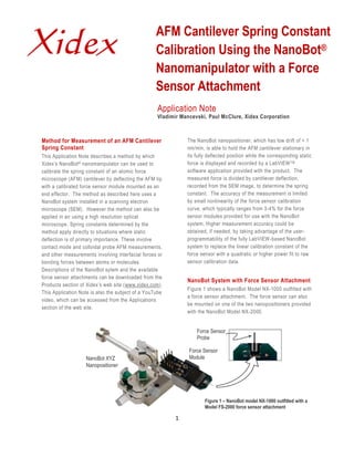
- 1. Xidex AFM Cantilever Spring Constant Calibration Using the NanoBot® Nanomanipulator with a Force Sensor Attachment Application Note Vladimir Mancevski, Paul McClure, Xidex Corporation Method for Measurement of an AFM Cantilever The NanoBot nanopositioner, which has low drift of < 1 Spring Constant nm/min, is able to hold the AFM cantilever stationary in This Application Note describes a method by which its fully deflected position while the corresponding static Xidex’s NanoBot ® nanomanipulator can be used to force is displayed and recorded by a LabVIEW TM calibrate the spring constant of an atomic force software application provided with the product. The microscope (AFM) cantilever by deflecting the AFM tip measured force is divided by cantilever deflection, with a calibrated force sensor module mounted as an recorded from the SEM image, to determine the spring end effector. The method as described here uses a constant. The accuracy of the measurement is limited NanoBot system installed in a scanning electron by small nonlinearity of the force sensor calibration microscope (SEM). However the method can also be curve, which typically ranges from 3-4% for the force applied in air using a high resolution optical sensor modules provided for use with the NanoBot microscope. Spring constants determined by the system. Higher measurement accuracy could be method apply directly to situations where static obtained, if needed, by taking advantage of the user- deflection is of primary importance. These involve programmability of the fully LabVIEW-based NanoBot contact mode and colloidal probe AFM measurements, system to replace the linear calibration constant of the and other measurements involving interfacial forces or force sensor with a quadratic or higher power fit to raw bonding forces between atoms or molecules. sensor calibration data. Descriptions of the NanoBot sytem and the available force sensor attachments can be downloaded from the NanoBot System with Force Sensor Attachment Products section of Xidex’s web site (www.xidex.com). Figure 1 shows a NanoBot Model NX-1000 outfitted with This Application Note is also the subject of a YouTube a force sensor attachment. The force sensor can also video, which can be accessed from the Applications be mounted on one of the two nanopositioners provided section of the web site. with the NanoBot Model NX-2000. Force Sensor Probe Force Sensor NanoBot XYZ Module Nanopositioner Figure 1 – NanoBot model NX-1000 outfitted with a Model FS-2000 force sensor attachment 1
- 2. The force sensor operates as a load cell for measuring End of Force forces with nanoNewton resolution. The Model FS-2000 Sensor Probe force sensor accommodates loads up to 2000 µN. The Model FS-180 accommodates loads up to 180 µN. Both compression and tension forces can be measured. The sensor element, which is based on single crystalline silicon, measures small forces with high precision. Unlike other load cells based on strain gages, the force sensors available for use with the NanoBot system measure the load by a change of capacitance. The readout electronics integrated in the sensor package convert the load into an output voltage proportional to AFM Tip the force. A LabVIEW™ based application for force feedback display is installed on a laptop computer running Windows OS which is provided with the system. Figure 3 – Force sensor probe and AFM tip with no Users can also create custom LabVIEW applications cantilever deflection and add these to the applications library provided with the NanoBot system. Cantilever Deflection Setup for Spring Constant Measurement The LabVIEW application for displaying and recording Figure 2 shows the setup for measuring the spring the force measured by the sensor is started with an on constant. The chip to which the AFM cantilever is screen command, or by using the joystick trigger. This attached is mounted on a fixture attached to an SEM starts a real time recording of force vs. time. With the stage. The Cantilever is a Budget Sensors model Tap LabVIEW Action running, the NanoBot nanopositioner is 300 G (www.budgetsensors.com) for which the spring commanded to move the stage carrying the force constant has a nominal specified value of 40 N/m and is sensor module so as to deflect the AFM cantilever from specified to lie in the range 20-75 N/m. The fine motion its initial position (Figures 2 & 3) to a new position, as mode of the NanoBot system is used to bring the 50 x shown in Figure 4, at which point the motion stops and 50 micron square end of the Si force sensor probe near, the static force remains constant. Figure 5 is an but not quite touching the AFM tip. Figure 3 is an expanded view showing the force sensor probe and expanded view showing the end of the force sensor AFM tip with the cantilever at maximum deflection. probe and the AFM tip in their initial positions, for which there is no cantilever deflection. End of Force Sensor Probe Mounted End of Force Sensor Probe Mounted on NanoBot Nanopositioner on NanoBot Nanopositioner AFM Cantilever AFM Cantilever (Fully Deflected) Chip Mounted on SEM Stage Chip Mounted on SEM Stage Figure 2 – Setup for Measurement of AFM Cantilever Figure 4 – Force sensor probe and AFM tip at maximum Spring Constant 2 cantilever deflection
- 3. End of Force Sensor Probe AFM Tip Figure 7 – Force sensor calibration data provided for individual sensor module Figure 5 – Force sensor probe and the AFM tip with cantilever at maximum deflection Spring Constant Determination Figure 6 shows the force vs. time history displayed by The maximum cantilever deflection, D MAX , is determined the LabVIEW application provided for use with the force by importing the captured video frames used to create sensor module. The measured force increases from Figures 3 and 5 into Adobe Photoshop, finding the zero to a maximum value F MAX = 197.38 µN. deflection in units of pixels, and then converting to µm Calibration data for the individual force sensor, like that using the pixel count associated with the scale bar shown in Figure 7, determines a linear calibrat ion provided with the SEM image. The result of this constant CFS, in Volts/ µN,for the individual module. A exercise is D MAX = 10.9 µm. The spring constant, k, is calibration constant determined this way has been then determined as entered into the LabVIEW Action prior to conducting the experiment. k = F MAX / D MAX = 18.1 N/m This measured spring constant is just below the 20-75 N/m range specified by the AFM tip manufacturer. Large deviations from the nominal spring constants provided by AFM tip manufacturers are not unusual. For example, a study [1] involving multiple laboratories Force Zero Force and different methods for spring constant determination Measured at Recorded Prior to showed similar large deviations of measured spring Maximum Deflection constants from manufacturers’ specifications. Inspection Deflection the reference cantilevers used in the study revealed chipping damage on the edge of the handle chip and debris particles on surfaces of the test cantilevers. The inference is that these two are related and chipping damage produced during handling of the test chips generated the debris particles. Figure 6 – Force vs. time history displayed by LabVIEW Users of a NanoBot system equipped with a force application sensor can measure the spring constant of an AFM cantilever intended for use in an application that requires accurate knowledge of its spring constant in a few minutes using the method described here. If no 3
- 4. SEM is available, the same technique can be used in air Xidex Corporation with a high resolution optical microscope equipped with digital image capture. Unlike alternative methods for Xidex manufactures and sells the NanoBot ® system, an determining the spring constants of AFM cantilevers easy-to-use, highly versatile, user-programmable [refs 2 to 5], there is no need to measure the resonant nanomanipulator built for use inside scanning elec tron frequency of the cantilever, add test masses, perform microscopes (SEMs) and focused ion beam (FIB) tools. finite element analysis, or make detailed measurements The NanoBot transforms a SEM or FIB into a workshop of cantilever geometry. for nanodevice fabrication and testing. Xidex Corporation was founded in 1997 as an Austin- References based Texas Corporation by Vladimir Mancevski, President and Chief Technology Officer and Dr. Paul F. [1] Richard S. Gates, David Mendels and Daisuke McClure, CEO. Fujita, “Mini Round Robin on AFM Cantilever Spring Constant Calibration,” VAMAS Technical Report No 49, March 2009 NanoBot Sales (http://www.vamas.org/twa29/documents/2009_vam as_twa29_report_49_mrr_afm_cantilever_calibratio n.pdf) For product inquiries please contact: [2] J. E. Sader, I. Larson, P. Mulvaney and L. R. Dr. Ray Eby White, "Method for the calibration of atomic force Nanobiosystems, Inc. microscope cantilevers,” Review of Scientific phone: 312-545-6527 Instruments, 66, 3789-3798 (1995) e-mail: nanoray@sbcglobal.net [3] J. E. Sader "Calibration of atomic force microscope cantilevers" (REVIEW) Encyclopedia of Surface and Colloid Science, Ed: A. Hubbard, 846-856 For direct contact: (2002) Xidex Corporation [4] Christopher T. Gibson, Daniel J. Johnson, 8906 Wall Street, Suite 703 Christopher Anderson, Chris Abell, and Trevor Ray, Austin, Texas 78754 “Method to determine the spring constant of atomic phone: 512-339-0608 force microscope cantilevers,” Rev. Sci. Instrum. fax: 512-339-9497 75, 565 (2004). e-mail: info@xidex.com [5] Bo-Yi Chen, Meng-Kao Yeh, and Nyan-Hwa Tai, web: www.xidex.com “Accuracy of the Spring Constant of Atomic Force Microscopy Cantilevers by Finite Element Method,” Anal. Chem., 2007, 79 (4), pp 1333–1338. © 2011, Xidex Corporation. All right reserved. NanoBot, Xidex, and the Xidex logo are trademarks of Xidex Corporation. Other trademarks are property of their respective owners. Product specifications and descriptions in this document are subject to change without notice. 110314 4