3. 1 FOREWORD
1.1 General
This manual has been written for the users of ULTRA TENS Pain Relief Device.
It contains general information on the operation, precautionary practices, and
maintenance information. In order to maximize its use, efficiency, and the life of the
system, please read this manual thoroughly and become familiar with the controls, as
well as the accessories before operating the system.
Pay attention to the following before using ULTRA TENS:
1. Keep yourself informed of the contra-indications (see chapter 3).
2. The apparatus may not be used in close proximity (i.e. less than 2 meters) to
shortwave equipment.
3. The apparatus may not be used in so-called “wet rooms” (hydrotherapy
rooms).
The manufacturer can not be held responsible for the results of using this
apparatus for any purposes other than described in these operating instructions.
1.2 Therapy possibilities
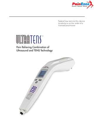
This is an apparatus therapy unit that offers both ultrasound therapy and
electrotherapy, which can be combined. Pain affects the quality and enjoyment
of life, especially for those who suffer chronic pain. ULTRA TENS is ultrasound
and electrotherapy therapy device for the treatment of chronic and acute muscular
pain. The applicator has a radiant surface of 4.0cm2 and an operating frequency of 1
MHz. Combination therapy of ultrasound and electrotherapy is, for instance, ideal to
localize trigger points and or pain points.
1.3 Applicator
The ultrasound applicator is one-frequency head. This applicator can now supply
1 MHz ultrasound. The head has excellent beam characteristics, fully meeting the
requirements of the existing standards. The excellent beam characteristics, ergonomic
design and effective contact control of the single-frequency applicator make an optimal
treatment possible.
1.4 Finally
You have made a wise choice in selecting the product. We are confident that
your unit will continue to give satisfaction over many years of use. Nevertheless, if
you have any queries or suggestions, please contact your authorized distributor.
CAUTION: This equipment is to be used only under the prescription and supervision
of a licensed practitioner
3
4. 2 SAFETY PRECAUTIONS
2.1 PRECAUTIONARY DEFINITIONS
The precautionary instructions found in this section and throughout this manual are
indicated by specific symbols. Understand these symbols and their definitions before
operating this equipment. The definition of these symbols is as follows;
Caution: Text with a “CAUTION” indicator will explain possible safety
infractions that could have the potential to cause minor to moderate injury or damage
to equipment.
Warning: Text with a “WARNING” indicator will explain possible safety
infractions that will potentially cause serious injury and equipment damage.
Danger: Text with a “DANGER” indicator will explain possible safety
infractions that are imminently hazardous situations that would result in death or
serious injury.
2.2 Caution
Caution
1) Read, understand, and practice the precautionary and operating instructions.
Know the limitations and hazards associated with using any ultrasound device.
Observe the precautionary and operational decals placed on the unit.
2) Keep yourself informed of the contraindications.
3) DO NOT operate the device when connected to any other medical devices.
4) DO NOT operate this unit in an environment where other devices are used that
intentionally radiates electromagnetic energy in an unshielded manner.
5) Ultrasound should be routinely checked before each use to determine that all
controls function normally, especially that the intensity control does properly
adjust the intensity of the ultrasonic power output in stable manner. Also,
determine that the treatment time control does actually terminate ultrasonic power
output when the timer reaches zero.
6) DO NOT use sharp objects such as pencil point or ballpoint pen to operate the
buttons on the control panel.
4
5. 7) The Ultrasound Applicator with care. Inappropriate handling of the Ultrasound
applicator may adversely affect its characteristics.
8) Before each use, inspect the Ultrasound Applicator for cracks, which may allow
the ingress of conductive fluid.
9) Inspect Applicator cables and associated connectors before each use.
10) The ultrasound therapy controls unit is not designed to prevent the ingress of
water or liquids. Ingress of water of liquids could cause malfunction of internal
components of system and therefore create risk of injury to the patient.
11) Caution should be used:
For patients with suspected or diagnosed epilepsy.
For patients with suspected or diagnosed heart problems.
12) Caution should be used in the presence of the following:
When there is a tendency to hemorrhage following acute trauma or fracture.
Following recent surgical procedures when muscle contraction may disrupt
the healing process.
Over the menstruating or pregnant uterus.
Over areas of the skin which lack normal sensation.
13) Some patients may cause skin irritation or hypersensitivity due to the electrical
stimulation or electrical conductive medium. The irritation can usually be reduced
by using an alternate conductive medium or alternate electrode placement.
14) Electrode placement and stimulation settings should be based on the guidance of
the prescribing practitioner.
15) Never apply electrodes over irritated or broken skin.
16) The device should be kept out of the children.
17) The device should be used only with the leads and electrodes recommended for
use by the manufacturer.
18) Do not use in the bath or shower. The device should not be submerged in water or
other liquids as this may startle the patient and possibly damage the device.
19) The use of heat and cold producing devices, such as electric heating blankets,
heating pads or ice packs, may impair the performance of the electrodes or alter
the patient’s circulation and increase the risk of injury to the patient.
20) The device should not be used on driving, operating machinery, or during any
activity in which in voluntary muscle contractions may put the user at
under risk of injury.
2.3 Warning
Warning
1) Care must be taken when operating this equipment around other equipments.
Potential electromagnetic or other interference could occur to this or to the other
equipment. Try to minimize this interference by not using other equipment in
conjunction with it.
5
6. 2)
3)
4)
5)
6)
7)
8)
9)
10)
11)
12)
13)
14)
15)
16)
17)
18)
19)
20)
21)
22)
23)
24)
25)
The device may not be used in close proximity (i.e. less than 2 meters) to
short-wave equipment.
Avoid exposure to direct sunlight, rain, excessive dust, moisture, mechanical
vibrations and shocks.
The device may not be used in so-called “wet rooms”(hydrotherapy rooms)
Only use the device for the recommended applications. The device should be
used under medical supervision.
Before administering any treatment, you should become acquainted with the
operating procedures for each program of treatment available, as well as the
indications, contraindications, warnings, and precautions. Consult other resources
for additional information regarding the application of Electrotherapy and
ultrasound.
Do not use solvents to clean the device.
A damaged device must no longer be used.
The device must only be serviced, repaired and opened by authorized sales
centre.
Dispose of the device in accordance with local regulations. Keep the operating
instructions with the device.
Pregnant and nursing women should use the device cautiously.
Avoid use over or near bone growth centers until bone growth is complete.
Treatment time should not exceed 30min a day.
Don’t use a cell phone while using the device.
Patients with sensitivity to the coupling gel should use the device cautiously.
Stimulation should not be applied over the carotid sinus nerves, particularly in
patients with a known sensitivity to the carotid sinus reflex.
Stimulation should not be applied over the neck or mouth.
Severe spasm of the laryngeal and pharyngeal muscles may occur and the
contractions may be strong enough to close the airway or cause difficulty in
breathing.
Stimulation should not be applied transcerebrally (across the head), over the
Carotid sinus (where the jaw meets the neck), over metal implants or in
conjunction with sleep apnea or heart monitors.
Stimulation should not be applied transthoracically. Since the introduction of
electrical current into the heart may cause cardiac arrhythmias.
Stimulation should not be applied swollen, infected or inflamed areas or skin
eruptions, e.g. phlebitis, thrombophlebitis, varicose veins, etc.
Stimulation should not be applied over, or in proximity to cancerous lesions.
Always keep the applicator in constant motion.
Use ample conductive gel to ensure good coupling throughout the treatment. If
needed, apply when setting intensity.
U.S.A. Federal Law restricts these devices to sale by, or on the order of, a
physician or licensed practitioner. This device should be used only under the
continued supervision of a physician or licensed practitioner.
6
7. 2.4 Danger
Danger
Patients with an implanted neurostimulation device must not be treated with or be
in close proximity to any shortwave diathermy, microwave diathermy, therapeutic
ultrasound diathermy, or laser diathermy anywhere on their body. Energy from
diathermy (shortwave, microwave, ultrasound, and laser) can be transferred through
the implanted neurostimulation system, can cause tissue damage, and can result in
severe injury or death. Injury, damage, or death can occur during diathermy therapy
even if the implanted neurostimulation system is turned “off.”
Biohazardous materials
Handle, clean, and dispose of components and accessories that have come in contact
with bodily fluids according to national, local, and facility rules, regulations, and
procedures.
2.5 Adverse reaction
z
z
Skin irritation, inflammation, and electrode burns beneath the electrodes are
potential adverse reactions.
Perform the following procedures to avoid the negative effects of ultrasound
therapy.
¾ Applicator Movement
If movement of the applicator is too slow, the patient may feel periosteal pain
characterized by a deep ache or pain. If motion is too fast, or if the applicator does not
maintain good contact with the skin, the therapeutic effect of the sound waves will be
reduced and the applicator may overheat.
¾ Patient Susceptibility
Some patients are more sensitive to ultrasound output and may experience a reaction
similar to a heat rash. Be sure to inspect the treatment area during and following
treatment, and discontinue if an adverse reaction does occur.
¾ Coupling
Coupling is described as contact between the applicator and the treatment site and
may be accomplished through the use of a coupling agent, such as gel, lotion.
Anything used as a coupling agent must be highly conductive. Air is a very poor
conductor of ultrasonic waves
7
9. 4)
5)
6)
7)
8)
9)
10)
Localized inflammation
Thrombosis
Pregnancy
Pacemakers
Metal implants
Cancerous lesions
Eye area
3.5 Contra-indications combination therapy
Combination therapy contra-indications refer to ultrasound therapy and electrical
stimulation therapy Contra-indications.
4 PRESENTATION
4.1 Presentation of the device
1) Applicator
2) On/Off Switch
3) AC/DC Adapter connector
Caution: Federal law (USA) restricts this device
to sale by or on the order of a physician
Manufactured for Current Solutions, LLC
3814 Woodbury Dr, Austin, TX USA 78704
www.currentsolutionsnow.com
4) Liquid Crystal Display
5)
6) “
7)
button
button
button
8) Electrode connect end
4.2 Liquid crystal display
1)
Program indicator
9
10. 2)
3)
4)
5)
6)
7)
Ultrasound contact indicator
Timer
Time display or Duty cycle display
Output intensity
Electrode contact indicator
Duty cycle setting
4.3 Key Function
“
“
” On/Off Switch
With this Switch ULTRA TENS is turned on or off.
” button
Stop treatment working
Program select
“
” button
Setting state
Combination therapy: Increase Duty cycle
Working state
Electrotherapy : Increase stimulate intensity
Ultrasound therapy: Increase Duty cycle
Combination therapy: Increase stimulate intensity
“
” button
Setting state
Combination therapy: Decrease Duty cycle
Working state
Electrotherapy : Decrease stimulate intensity
Ultrasound therapy: Decrease duty cycle
Combination therapy: Decrease stimulate intensity
5 INSTALLATION
5.1 Before Use
Remove the equipment and all accessories from shipping carton and giftbox. Visually
check if there is any damage or missing parts or accessories.. If yes, please report to
10
11. local dealer or retailer where you purchase this unit. Your ultrasound equipment
contains the following accessories.
Part
Quantity
ULTRA TENS
Operating instruction
Electrode 50*100mm
Lead for electrical
Adapter 100-240V 50 or 60 Hz
Lead for adapter
Ultrasound transmission gel
1
1
2
1
1
2
1
1
1
5.2 Connection
Prior to connecting this apparatus to the power supply, check that the voltage and
frequency stated on the rating label match with the available power supply.
The power adapter is a part of the supply circuit on which the device’s safety
partly depends. The approvals for ULTRA TENS are only valid if used in
combination with this type of adapter MM1510 SERIES.
Caution: It is not permitted to connect ULTRA TENS to another type
of adapter other than MM1510 SERIES.
Caution: Connection of accessories other than the ones specified by the
manufacturer can adversely affect the safety of patients and proper functioning of the
equipment; therefore, it is not permitted.
5.3 Connection of the power adapter
Connect the power adapter to the connector.
Connect the power adapter to a wall socket.
5.4 Switching on
Switch on the apparatus, using On/Off switch
5.5 Select the therapy program
The device has 15 kinds of treatment program. Users can press “
11
”
12. button to select preferred treatment program:
0 C program: Ultrasound + Electrical Stimulation combination therapy
( C1 C7 program).
0 U program: Ultrasound therapy
0 E program: Electrotherapy ( E1 E7 program)
5.6 Disconnect from power adapter
z
Switch off the unit by switching. “
z
Pull out the power adapter from the wall socket.
” to
position.
6 OPERATION
6.1 Measures with regards to treatments
6.1.1 Electrotherapy
Before treatment
z Ensure there are no contraindications to treatment
z Inspect the treatment area skin seriously for any abrasions, inflammation,
surface veins etc.
z Clean the skin of the treatment area with soap or alcohol (70%).
z If the skin is hairy, shaving can get optimal treatment.
z Test the heat sensibility of the treatment area.
6.1.2 Ultrasound
z
z
z
z
z
z
z
Before treatment
Ensure there are no contraindications to treatment
Test the warm sensibility of the treatment area.
Clean the skin of the treatment area with soap or alcohol (70%).
If the skin is hairy, shaving can get optimal treatment.
Apply some ultrasound transmission gel onto the treatment area. The gel is
conducive and ensures effectiveness. (Please purchase the ultrasound gel
with FDA approved)
During treatment
Move the applicator in a circular motion. The area treated should be two
times the diameter of the applicator.
In case of poor transmission of ultrasound energy, it is advised to add more
gel or reposition the ultrasound-head.
12
13. Caution
The applicator has to be moved in a normal speed - not too slow to avoid
inducing heat; nor too fast to prevent a bad contact which would reduce the
effectiveness of the treatment.
After treatment
Clean the skin of the treated area as well as the ultrasound head by using a
towel or a tissue.
the ultrasound head should be cleaned up 70% alcohol.
Check if there are any signs of improvement (e.g. pain, circulation or
mobility).
6.1.3 Combination therapy
See both chapters 6.1.1. Electrotherapy and 6.1.2. Ultrasound.
6.2 Operating the apparatus
6.2.1 Introduction
6.2.1.1 Switch on the apparatus
Switch on the apparatus by switching. “
” to
position.
6.2.1.2 Select the therapy program
Select the therapy program by referring to chapter 5.5.
6.2.1.3 Adjusting intensity
Pressing
and
button to increase or decrease the output intensity.
6.2.1.4 Ultrasound duty cycle
Ultrasound therapy: The ultrasound duty cycle is adjusted with
and
control button. The ultrasound intensity can be adjusted in 0~5, the corresponding
duty factor is 0%, 5%, 20%, 50%, 80% and 100%.
Combination therapy (Ultrasound with Electrotherapy) by pressing
and
button and hold for 3 seconds to enter the setting state. Press
button to select duty cycles. The ultrasound duty cycle will be
and
displayed in 5%, 20%, 50%, 80%, or 100%.
13
14. 6.2.1.5 Emergency stop
Pressing
button will stop all active treatment.immediately.
6.2.2 Electrotherapy
Connect the electrode pads to the unit as below picture.
Caution: The device must be turned off before connecting the lead wires to
the device.
Press the
button to select the Electrotherapy program (therapy program
E1 E7).
Press
or
button to increase or decrease the output current strength.
When reach the maximal value, the value won’t be changed even if user continue
to press it. The amplitude value can be adjusted in 1V for each step. The intensity
14
15. Caution
In standby mode, the LCD backlight is Cyan. When the strength is less than 50 levels,
LCD backlight is Green. When the strength is equal or more than 50 levels, LCD
backlight will turn to Purple.
When the electrodes are not in good contact with patient, or the wires is not well
connected to the electrodes or main unit, the LCD backlight will turn to Blue.
6.2.3 Ultrasound therapy
Press
button to select the Ultrasound therapy.
Pressing
or
control button to select the duty cycle (please refer to
6.2.1.4). When you put the applicator onto your body and have a good contact
(after applying the ultrasound gel onto the treatment area), the device will start
emitting ultrasound energy.
Apply some ultrasound gel onto the treatment area. The gel acts as a conducive
substance and ensures effectiveness. (Please purchase the ultrasound gel with
FDA approved label)
Caution
During standby mode, the LCD backlight is Cyan. During treatment mode, it will be
changed to Green.. When the duty cycle is more than 5%, or the applicator is not in
good contact with the body, the LCD color will turn to blue.
Caution
The device works without vibration. You must move the applicator in a normal speed
with circular motion around the treatment point. After 10 minutes when the treatment
is finished, the device will enter the waiting state. We do not recommend user to start
the treatment again.
15
16. 6.2.4 Combination therapy
Connect the electrode pad to the unit as below picture. Please use single-electrode
lead to connect electrodes with the unit. The applicator as negative electrode. The
current flows between the positive electrode and the applicator.
Caution: The device must be turned off before connecting the lead wires to
the device.
Press
button to select the combination therapy and program (therapy
program C
.
Press hold
and
button for 3 seconds to enter the setting mode. Then
press increase and decrease to select duty cycle (please refer to 6.2.1.4). When
you put the applicator onto your body and have a good contact (using ultrasound
gel), the device will start emitting ultrasound energy.
Press
or
control button to increase or decrease output current strength.
When reaching the maximal value, the value won’t be changed even if user
continues to press it. The amplitude value can be adjusted in 1V for each step.
The intensity range is from 0V to 80V(500 Load)
Apply some ultrasound transmission gel onto the treatment area. The gel acts as a
conducive substance and ensures effectiveness. (Please purchase the ultrasound
gel with FDA approved)
16
17. Caution
In standby mode, LCD backlight is Cyan. When the strength is less than 50 levels,
LCD backlight is Green. When the strength is equal or more than 50 levels, the LCD
backlight will change to Purple. When the duty cycle is more than 5%, or the
applicator is not in good contact with the body, or the electrode cable is not well
connected to the electrode or main unit, the LCD color will turn to Blue.
Caution
The device works without vibration. You must move the applicator in a normal speed
with circular motion around the treatment point. After 10 minutes when the treatment
is finished, the device will enter the waiting state. We do not recommend user to start
the treatment again.
6.3 The applicator
Applicator is a precision instrument. Great care is taken in the development and
production in order to obtain the best possible beam characteristics. Rough treatment
(jarring or dropping) can adversely affect these characteristics, and must therefore be
avoided.
6.4 The contact medium
In the Ultrasound therapy or combination therapy, Coupling is described as
contact between the applicator and the treatment site. In order to ensure efficient
transfer of energy, a contact medium is required. Air causes virtually total
reflection of the ultrasound energy. The best medium for the transfer of
ultrasound energy is a gel. (Please purchase the ultrasound gel with FDA
approved)
Liberally apply transmission gel or equivalent to the treatment area.
Move the applicator during therapy session in a circular motion. The area treated
should be two times the diameter of the applicator.
Caution: Never apply the gel to the applicator. The applicator will register
this as contact and may emit ultrasound energy, which could damage the applicator.
17
18. 7 MAINTENANCE
7.1 Cleaning of the apparatus
Switch off the apparatus and disconnect it from the power supply. The apparatus can
be cleaned with a damp cloth. Use lukewarm water and a non-abrasive liquid
household cleaner (no abrasive, no alcohol content solution). If a more sterile cleaning
is needed, use a cloth moistened with an antimicrobial cleaner.
Caution: Do not submerse the apparatus in liquids. Should the unit
accidentally become submersed, contact the dealer or Authorized Service center
immediately. Do not attempt to use a system that has been wet inside until inspected
and tested by a Service Technician Certified by Authorized Service center. Do not
allow liquids to enter the ventilation holes.
7.2 Cleaning of the applicator
The applicator should be regularly inspected for damage, e.g. hairline cracks, which
could allow penetration by liquids. Clean the contact surface immediately after each
treatment. Make sure that no ultrasound gel remains on the applicator. We further
recommend cleaning the head and cable daily, using lukewarm water. The applicator
can be disinfected using a cloth moistened with 70% alcohol.
7.3 Cleaning the lead wires
Periodically wipe the lead wires clean with a cloth dampened in a mild soap solution,
and then gently wipe them dry. Use of rubbing alcohol on the lead wires will damage
the insulation and dramatically shorten their life.
7.4 Maintenance
Maintenance and all repairs should only be carried out by an authorized agency.
The manufacturer will not be held responsible for the results of maintenance or
repairs by unauthorized persons.
Opening of the equipment by unauthorized agencies is not allowed and will
terminate any claim to warranty.
Check the unit before each use for signs of wear and/or damage. Replace wear
items as required.
Wear items are:
1. Electrodes
2. Lead wires
18
19. 8 TROUBLESHOOTING PBOBLEMS
For optimal use:
1) Replace lead wires annually.
2) Please follow the directions on the electrode packaging for the care of electrodes.
The life of the electrodes varies, depending on skin conditions, skin preparation,
storage and climate. Replace electrodes that no longer stick.
3) Ensure the ultrasound gel is used between the applicator and the body.
4) NOTE: If the following measures fail to alleviate the problem, please call the
authorized agency or your supplier.
19
20. Problem
Displays fail to light
up
Possible Cause
Adapter contact failure
Stimulation weak
Electrodes
1. Dried out or contaminated 1. Replace.
2. Electrodes must be a
2. Placement
minimum of 2 inches apart.
Lead wires
1. Replace.
1.Old/worn/damaged
Stimulation stops
Gel
1. insufficient gel
Poor electrode contact
Solution
Ensure adapter is
connect .Check the
following
contacts:
• All contacts are in place.
• All contacts are not
broken.
1. increase sufficient gel
Reapply electrodes, secure
firmly.
Damaged or worn electrodes Replace
or lead wires
Use the ultrasound gel
Decrease intensity.
Decrease duty cycle
Electrodes are too close
together
Stimulation is
uncomfortable.
Not contact medium
Intensity is too high
Reposition the electrodes.
Electrodes must be a
minimum of 2 inches apart.
Damaged or worn electrodes Replace.
or lead wires
Electrode active area size is
too small.
Stimulation is
ineffective.
Replace electrodes with
ones that have an active area
no less than 5.58 in2
(36.0cm2).
Improper electrode and
applicator placement
Reposition electrode and
applicator
Unknown
Contact clinician.
20
21. 9 SPECIFICATIONS AND TECHNICAL DATA
9.1 Technical date of Ultrasound
Acoustic frequency:
Generator output:
Modulation wave shape:
Duty factor:
Treatment time:
Actual radiating area(AER):
Max intensity
RBN(MAX):
Program
Beam type:
Material of applicator:
1MHz ± 10%
4.0W ± 20%
20Hz ± 10%
5%,20%, 50%, 80%, 100%
10min
4.0cm2 ± 20%
1.0W/cm2 ± 20%
5.0
U
Collimated
Aluminium
9.2 Technical data of Electronic Stimulator
Output characteristics:
Reading resolution:
Treatment time
Program:
Output wave
Frequency:
Pulse duration:
constant voltage(CV)
1V
30min
E
Monophasic square pulse
2~150Hz
60~250uS
9.3 Technical data of combination ultrasound and electrical Stimulator
Output characteristics: Constant Voltage(CV)
Reading resolution: 1V
Treatment Time 10min
Program:
Output wave
Frequency:
Pulse duration:
C
Monophase pulse
2~150Hz
60~250uS
9.4 Technical data of ULTRA TENS main part
Supply voltage:
Current consumption:
Working current:
Safety class:
Dimension:
Protection degree:
15V
10W
< 1.0A
Class II, BF-type
358mm(L)x64mm(W)x97mm(H)
IPX7 for transducer (5mm)
21
22. 9.5 Technical data of power supply
Supply voltage:
Frequency:
Power
Output voltage:
Output current:
Dimensions:
100V~240V
50Hz~60Hz
18W
15V DC
1.0A
110mm(L)x54mm(W)x33mm(H)
9.6 Environmental conditions
Environment temperature:5~40
with a relative humidity of
Operating conditions
30%~75% Atmospheric pressure
from 700~1060hPa
Environment temperature:-10~50
with a relative humidity of
Storage conditions
10%~90% Atmospheric pressure
from 700~1060hPa
9.7 Program list table
22
23. 10 STORAGE
For a prolonged pause in treatment, store the device with the adapter in a dry room
and protect it against heat, sunshine and moisture. Store the machine in a cool,
well-ventilated place. Never place any heavy objects on the machine.
11 DISPOSAL
Please dispose of the device in accordance with the directive 2002/96/EC
– WEEE (Waste Electrical and Electronic Equipment). Contact your
local distributor for information regarding disposal of the unit and
accessories.
12 EMC TABLE
Guidance and manufacturer’s declaration - electromagnetic emissions
The device is intended for use in the electromagnetic environment specified below.
The customer or the user should assures that it is used in such an environment.
Emissions
test
RF emissions
CISPR 11
RF emissions
CISPR11
Harmonic
emissions
lEC
61000-3-2
Voltage
fluctuations /
flicker
emissions
lEC
61000-3-3
Compliance
Electromagnetic environment - guidance
Group 2
The device uses RF energy only for its internal
function. Therefore, its RF emissions are very low
and are not likely to cause any interference in
nearby electronic equipment.
Class B
Not applicable
The device is suitable for use in all establishments
other than domestic and those directly connected to
the public low-voltage power supply network that
supplies buildings used for domestic purposes.
Not applicable
23
24. Guidance and manufacturer’s declaration — electromagnetic immunity
The device is intended for use in the electromagnetic environment specified below.
The customer or the user should assure that it is used in such an environment.
Immunity test
IEC 60601
test level
Compliance
level
Electrostatic
Electromagnetic environment guidance
Floors should be wood, concrete or
discharge
±6 kV contact
±6 kV contact
ceramic tile. If floors are covered with
(ESD)
±8 kV air
±8 kV air
synthetic material, the relative
humidity should be at least 30%.
lEC 61000-4-2
24
25. Guidance and- manufacturer’s declaration. Electromagnetic immunity
The device is intended for use in. the electromagnetic environment specified below. The customer
or the user of the should assure that it is used in such an environment.
Immunity
IEC 60501 test
Compliance
test
level
level
Electromagnetic environment - guidance
Portable and mobile RF communications
equipment should be used no closer to any
part of the device, including cables,
than the recommended
separation distance calculated from the
equation applicable to the frequency of the
transmitter.
Recommended separation distance
Conducted RF
lEC 61000-4-6
Radiated RF
lEC 61000-4-3
3 Vrms
150 kHz to 80
3 Vrms
MHz
3 V/m
80 MHz to 2.5
3 V/m
, 80MHz to 800MHz
GHz
, 800MHz to 2,5MHz
where P is the maximum output power
rating of the transmitter In watts (W)
according to the. transmitter manufacturer
and d Is the recommended separation
distance in meters (m).
Field strengths from fixed RF transmitters,
as determined by an electromagnetic site
survey,a should be less than the compliance
level in each frequency range.b
Interference may occur In the vicinity of
equipment marked with the following
symbol:
NOTE I At 80 MHz ends 800 MHz. the higher frequency range applies.
NOTE 2 These guidelines may not apply in all situations. Electromagnetic propagation is affected
by absorption and reflection from structures, objects and people.
a
Field strengths from fixed transmitters, such as base stations for radio (cellular/cordless)
telephones and land mobile radios, amateur radio, AM and FM radio broadcast and TV broadcast
cannot be predicted theoretically with accuracy. To assess the electromagnetic environment due
to fixed RF transmitters, an electromagnetic site survey should be considered. If the measured
field strength in the location in which the device is used exceeds the applicable RF compliance
level above, should be observed to verify normal operation. If abnormal performance is observed,
additional measures may be necessary, such as reorienting or relocating the device.
b
Over the frequency range 150 kHz to 80 MHz, field strengths should be less than [Vi] V/m.
25
26. Recommended separation distances between portable and mobile RF communications
equipment and the device
The device is intended for use in an electromagnetic environment in which radiated RF
disturbances are controlled. The customer or the user device can help prevent
electromagnetic interference by maintaining a minimum distance between portable
and mobile RF communications equipment (transmitters) and the device as recommended
below, according to the maximum output power of the communications equipment.
Separation distance according to frequency of transmitter
Rated maximum output
power
of transmitter
m
150 kHz to 80 MHz
80 MHz to 800
800 MHz to 2,5
MHz
GHz
W
0,01
0.12
0.12
0.23
0,1
0.38
0.38
0.73
1
1.2
1.2
2.3
10
3.8
3.8
7.3
100
12
12
23
For transmitters rated at a maximum output power not listed above, the recommended
separation distance d in meters (m) can be estimated using the equation applicable to the
frequency of the transmitter, where P is the maximum output power rating of the transmitter in
watts (W) accordable to the transmitter manufacturer.
NOTE I At 80 MHz and 800 MHz. the separation distance for the higher frequency range
applies.
NOTE 2 These guidelines may not apply in all situations. Electromagnetic propagation is
affected by absorption and reflection from structures, objects and people.
26
27. 13 .WARRANTY
Please contact your dealer or the device centre in case of a claim under the warranty.
If you have to send in the unit, enclose a copy of your receipt and state what the
defect is.
The following warranty terms apply:
1) The warranty period is 18 months from date of purchase. In case of a warranty claim,
the date of purchase has to be proven by means of the sales receipt or invoice.
2) Defects in material or workmanship will be removed free of change within the
warranty period.
3) Repairing under warranty do not extend the warranty period either for the unit or
for the replacement parts.
4) The following is excluded from the warranty:
All damage which has arisen due to improper treatment, e.g. non-observance
of the user instruction.
All damage which is due to repairing or tampering by customer or
unauthorized third parties.
Damage which has arisen during transportation from the manufacturer to the
consumer or to the service centre.
27
28. 14 .NORMALZED SYMBOLS
ON/OFF Switch
Program Select/Stop
Intensity Increase
Intensity decrease
Protected against the effects of immersion
Power polarity
Power connect
Electrode connect
REF
203475
Mode or type designation, order number
Class II symbol
Symbol for protection against electric shock: Type BF
SN:XXXXXXX
LOT : MED2011WHK10/01
Serial number attached on the topside and sticker on the packaging
LOT: Lot Number
MED: Medical instrument
2011: Number
WH: Color
K: Year
10: Month
01: Batch Number
Disposal in accordance with Directive 2002/96/EC (WEEE)
0197
Complies with the European Medical Device Directive (93/42/EEC)
and amended by directive 2007/47/EC requirements.
Notified body TÜV Rheinland (CE0197)
28