Networking(CPM & PERT)
•Transferir como PPTX, PDF•
1 gostou•1,728 visualizações

Networking

Recomendados
Mais conteúdo relacionado
Mais procurados
Mais procurados (20)
Semelhante a Networking(CPM & PERT)
Semelhante a Networking(CPM & PERT) (20)
Último
Último (20)
Networking(CPM & PERT)
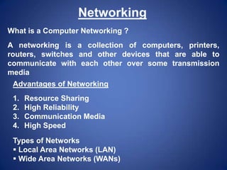
- 1. Networking What is a Computer Networking ? A networking is a collection of computers, printers, routers, switches and other devices that are able to communicate with each other over some transmission media Advantages of Networking 1. 2. 3. 4. Resource Sharing High Reliability Communication Media High Speed Types of Networks Local Area Networks (LAN) Wide Area Networks (WANs)
- 2. Local Area Networks (LAN) A Local Area Network (LAN) is a group of computers and network communicating devices within a limited geographic area, such as an office building. Wide Area Networks (WAN) A wide Area Networking (WAN) interconnects LANs. It is not restricted to a particular geographic area and may be interconnected around the world. No third party involvement here High data transfer speeds Generally less expensive technologies Limited geographic area Third party network is involved. Multiple interconnected LANs More sophistificated to implement than LANs Exists in an unlimited geographic area Less error resistance due to transmission travel distances
- 3. Features of LAN • • • • • • • Standard PC Hardware Resource Sharing Common Applications File Sharing Data Security Fault Tolerance Centralized Security
- 5. Peer to Peer Network
- 6. Peer to Peer Network In peer-to-peer networks, each computer is considered as a server as well as a client and holds its own accounts database. Each computer can share resources that it owns, like files, CD-ROM drives, printers, modems and fax machines. Eg. Windows workgroups.
- 7. Advantages of Peer to Peer Network • Security responsibility of each workstation • Each station runs same software • Each computer has its own accounts database • Cheap and easy to set up for small groups • No centralized server required
- 8. Open Systems Interconnect (OSI) model · · · · · · · Application Presentation Session Transport Network Data link Physical
- 10. Layer 1 - Physical Layer Provides • • • • Data Encoding Physical Medium Attachment Physical Medium Transmission Relates the electrical, optical mechanical and functional interfaces to the cable
- 11. Layer 2 – Data link Layer • • • • • • • Link Establishment and Termination Frame Traffic Control Frame Sequencing Frame Acknowledgment Frame Delimiting Frame Error Checking Media Access Management The data link layer consists of two sub layers: 1. LLC (logical link control) layer 2. MAC (Media Access Control) layer
- 12. Layer 3 -Network layer 1. Defines logical addressing 2. Routing occurs at this layer 3. Routing: routes frames among networks. 4. Subnet traffic control 5. Frame fragmentation 6. Logical-physical address mapping
- 13. Layer 4 - Transport layer provides: • • • • • • Message segmentation Message acknowledgment Message traffic control Session multiplexing Responsible for packet creation. Gateways operate at this layer.
- 14. Layer 5 - Session Layer 1. Session establishment 2. Session support 3. The session layer establishes, manages, maintains and terminates communication channels between software programs on network nodes.
- 15. Layer 6 - Presentation layer provides • • • • Character code translation Data conversion Data compression Data encryption
- 16. Layer 7 - Application layer • • • • • • • • • Resource sharing and device redirection Remote file access Remote printer access Inter-process communication Network management Directory services Electronic messaging (such as mail) Network virtual terminals Serves as a window for applications to access • network services
- 17. Topology of LAN In a bus topology : a single cable connects each workstation in a linear, daisy-chained fashion signals are broadcasted to all stations, but stations only act on the frames addressed to them
- 18. BUS TOPOLOGY Advantages • • • • • Easy to implement • Low Cost Easy to connect a computer or peripheral • to a linear bus Requires less cable length than a star top • Disadvantages Entire network shuts down if there is a break in the main cable Terminators are required at both ends of the backbone cable. Difficult to identify the problem if the entire network shuts down
- 19. In a ring topology : Unidirectional links connect the transmit side of one device to the receive side of another device. Devices transmit frames to the next device (downstream member) in the ring
- 20. Star Topology In a Star topology, each station is connected to a central hub or concentrator that functions as a multi-port repeater. Each station broadcasts to all of the devices connected to the hub. Physical LAN topologies are usually characterized as either bus or ring
- 21. STAR TOPOLOGY Advantages Disadvantages • • • • • • Easy Network • management Initial installation of star networks is easier • Network reliability is high. Easy to install and wire. No disruptions to the • network then connecting or removing devices. Easy to detect faults and to remove parts Requires more cable length than a linear topology. If the hub or concentrator fails, nodes attached are disabled. More expensive than linear bus topologies because of the cost of the concentrators.
- 23. TREE TOPOLOGY Advantages Disadvantages • • Point-to-point wiring for individual segments. Supported by several hardware and software venders • • • Overall length of each segment is limited by the type of cabling used. If the backbone line breaks, the entire segment goes down. More difficult to configure and wire than other topologies.
- 25. Local Area Network Cabling The earliest LANs used coaxial cables. Over time, the twisted Pair cables used in telephone systems were improved to carry higher frequencies and support LAN traffic. More recently, fibre optic cables have emerged as a high speed cabling option. Local Area Networks use four types of cables : Coaxial Unshielded Twisted Pair (UTP) Shielded Twisted Pair (STP) Fibre Optics
- 28. Unshielded Twisted Pair Unshielded twisted pair (UTP) cable is used for both LANs and telephone systems. UTP cables are composed of four colour-coded pairs of copper conductors twisted around each other. An outer jacket provides protection and keeps the pairs in alignment. UTP cable connects to devices via 8 pin modular connectors called RJ – 45 plugs. All LAN protocals can operate over UTP. Most modern LAN devices are equipped with RJ-45 Jacks
- 29. Shielded Twisted Pair (STP) STP cable is also used for Data Networks. It originated with IBM’s Token – Ring Networks. It shielding allow greater tolerances for protection from EMI interference, such as from fluorescent light fixtures and electronic motors.
- 30. Fibre Optics Fibre optics cables are the latest development in cabling technology. They are constructed from optical glass. There is a central glass filament, called the core, and surrounding layers of cladding, buffer coatings, strengthening materials and an outer jacket. Information is transmitted by wavelengths of light. This is accomplished through devices that convert electrical signals into rapid pulses of either LED or Laser light. Advantages of Fibre Optics High bandwidth capacity (many giga bits per second) Longer distances between devices (from 2 to over 60 Kilometers) immunity to electromagnetic interferences
- 32. Fibre optic cables are widely used in WANs for both voice and data communications. The primary barrier to their widespread use in LANs is the cost of electronics.
- 33. Physical Topology Common Cable Common Protocol Linear Bus Twisted Pair Coaxial Fiber Ethernet Local Talk Star Twisted Pair Fiber Ethernet Local Talk Star-Wired Ring Twisted Pair Token Ring Tree Twisted Pair Coaxial Fiber Ethernet
- 34. LAN Infrastructure Devices Repeaters Bridges Hubs Switches Routers
- 35. Repeaters Repeaters, located within physical layer of a network, regenerate and propagate signals from one to another. They do not change any information being transmitted, and they can not filter any information. Repeaters help to extend the distances of networks by boosting weak signals.
- 36. Bridges Bridges are intelligent repeaters. They regenerate transmitted signals, but unlike repeaters, they can also determine destinations.
- 37. Hubs Hubs connect all computer LAN connections into one device. They are nothing more than multiport repeaters. Hubs cannot determine destinations. They merely transmit to every line attached in a half-duplex mode
- 38. Routers Routers are a step up from bridges. They are able to route and filter information to different networks. Some routers can automatically detect problems and redirect information around the problem area. These are called “Intelligent routers.”
- 39. Switches Switches connects all computer LAN connections, the same as hubs do. The difference is that switches can run in fullduplex mode and are able to direct and filter information to and from specific destinations.
- 40. WAN infrastructure Devices ATM Switches Asynchronous Transfer Mode (ATM) Switches provide high speed transfer between both LANs and WANs.
- 41. Modem Modems convert digital and analog signals. At the source, modems convert digital signals to a form suitable for transmission over analog communication facilities (Public telephone lines). At the destination, modems covert the signal back to a digital format.
- 42. CSU/DSU (Channel Service Unit / Data Service Unit) CSUs / DSUs are similar to modems, however they send data in digital format across digital telephone loops. They are usually in a physical box, but they may come in two separate units. CSUs or DSUs Multiplexers A multiplexer combines multiple signals for transmission over a single circuit. This allows for the transfer of various data simultaneously, such as video, sound, text, etc.
- 43. Communication Servers Communication Servers are typically dial in/out servers that allow users to dial in from remote locations and attach to the LAN X.25 / Frame Relay Switches X.25 band Frame Relay Switches connect private data over public data circuits using digital signal. These units are very similar to ATM switches, but the transfer rate of data is not comparable.
- 44. Protocols Communication protocol or network protocol is the specification of a set of rules for a particular type of communication. A commonly used protocols : HTTP : Hyper Text Transfer Protocol TCP - Transmission Control Protocol IP - Internet Protocol Ethernet Protocol
- 45. Other Protocols FTP - File Transfer Protocol UDP - User datagram protocol ICMP - Internet Control Message Protocol Telnet Protocol IMAP - Internet Message Access Protocol (Previously called Interactive Mail Access Protocol) SMTP - Simple Mail Transfer Protocol NTP - Network Time Protocol NNTP - Network News Transfer Protocol