Pallet rack storage system
•
1 like•4,156 views

This document provides an overview of automated storage and retrieval systems (AS/RS). It describes the key components of an AS/RS including the storage structure, storage/retrieval machine, storage modules, and pick-and-deposit stations. It also distinguishes between different types of AS/RS such as unit load, deep-lane, mini-load, and vertical lift systems. The document outlines common objectives for automating storage operations and discusses applications of AS/RS in warehousing, order picking, and work-in-process storage.

Recommended
More Related Content
What's hot
What's hot (20)
Viewers also liked
Viewers also liked (13)
Similar to Pallet rack storage system
Similar to Pallet rack storage system (20)
Recently uploaded
Recently uploaded (20)
Pallet rack storage system
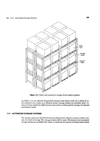
- 1. 335 Pallet Upright frame beam 11.3 Pallet rack system for storage of unit loads on pallets. ers. Figure 11.4, can alleviate this problem because each drawer pulls out to allow its entire contents to be readily seen. Modular drawer storage cabinets are available with a variety of drawer depths for different item sizes and are widely used for storage of tools and maintenance items. 11.4 cess the items in storage. The storage system itself is static. Mechanized and automated storage systems are available that reduce or eliminate the amount of human intervention
- 2. Chap. 11 I Storage Systems 336 Cahinet Drawer! Figure 11.4 Drawer storage. required to operate the system. The level of automation varies. In less-automated systems, loads are entered or retrieved control, with no human participa- under computer systems, tages as well as typical applications of automated storage systems. An automated storage system represents a significant investment, and it often requires a new and different way of doing business. Companies have different reasons for automating the storage function. Table 11.3 provides a list of possible objectives that a company may want to achieve by automating its storage operations.Automated storage systems divide into two general types: (1) automated storage/retrieval systems and (2) carousel storage systems. These two types are discussed in the following sections. An (ASIRS) can be defined as a storage system that performs storage and retrieval operations with speed and accuracy under a defined degree of automation. A wide range of automation is found in commercially available TABLE 11.3 Possible • To increase storage • To increase storage • To recover • To improve • To reduce • To improve safety • To improve control • To improve stock Objectives Automating a Company's Storage Operations capacity density factory floor security labor for space and reduce in the presently storage cost increase over inventories rotation • To improve customer • To increase throughput service used for storing work-in-process pilferage labor function productivity in storage operetlons
- 3. Sec. 11.4 Automated Storage 337 Systems svstems At the most sophisticated level. the operations are totally automated, computer c~ntrolled, and fully integrated with factory and/or warehouse oporarionsrat the other extreme, human workers control the equipment and perform the storage/retrieval transactions. Automated storage/retricval sy~tcms custom designed for each application, although the designs are based on standard modular components available from each respective AS/RS supplier. Our definition can be interpreted to include carousel storage systems. However, in the material handling industry, the carousel-based systems arc distinguished from AS/RSs. The biggest difference is in the construction of the equipment. The basic AS/R$ consists of a rack structure for storing loads and a storage/retrieval mechanism whose motions are linear (x-y-z rnotious). By contrast, a basic carousel system uses storage baskets suspended from an overhead conveyor that revolves around an oval track loop to deliver the baskets to a load/unload station. The differences between an ASiRS and a carousel storage system are summarized in Table 11.4. An AS/RS consists of one or more storage aisles that are each serviced by a storage/retrieval !,SIR) machine. (The SIR machines are sometimes referred to as cranes.)The aisles have storage racks for holding the stored materials. The SIR machines arc used to deliver materials to the storage racks and to retrieve materials from the racks. Each AS/RS aisle has one or more input/uutput stations where materials are delivered into the storage system or moved out of the system. The input/output stations are called pickup-and-deposit (P&D) stations in AS/RS terminology P&D stations can be manually operated or interfaced some form of automated handling system such as a conveyor or an AOVS. AS/RS Several important categories of automated age/retrieval system can be distinguished. The following are the principal types: stor- • Unit load AS/RS. The unit load AS/RS is typically a large automated system designed to handle unit loads stored on pallets or in other standard containers. The system is computer controlled, and the SIR machines are automated and designed to handle the unit load containers. A unit load AS/RS is pictured in Figure 11.5. The unit load system is the generic AS/RS. Other systems described below represent variations of the unit load ASfRS. TABlE 11.4 Differences Between an AS/RS and a Carousel Feature Storage structure AS/RS linear motions Storage/retrieval operation SJRmachinetravelsto compartments Replication capacity Multiple aisles, Svstarn Basic Rack system to support pallets shelf system to support tote Motions of Mnrage Storage or bins of SIR machine Carousel Storage Baskets suspended conveyor trolleys from each of rack structure structure consisting and machine Revolution trolleys of overhead around oval Conveyor in rack revolves baskets System overhead conveyor track to bring to ioad/unload Multiplecarousels • • • ch " consisting of oval track suspended bins station and
- 4. Chap. 11 I Storage Systems 338 (raek Irameworkl> Storegernodule SfRmaohino Piek-and-depcsit station A unit load automated storage/retrieval system. The deep-lane AS/RS is ahigh-density unit load storage system that is appropriate when large quantities of stock are stored, but the number of separate steer types (SKUs) is relatively small. Instead of storing each unit load so that it can be accessed directly from the aisle (as in a conventional unit load system), the deeplane system stores ten or more loads in a single rack, one load behind the next. Each rack is designed for "flow-through," with input on one side and output on the other side. Loads are picked from one side of the rack an SIR-type machine designed for retrieval, and another machine is used on the entry side of the rack for load input. ASiRS. This storage system is used to handle small loads (individual parts or supplies) that are contained in bins or drawers in the storage system. The SIR machine is designed to retrieve the bin and deliver it to a P&D station at the end of the aisle so that individual items can be withdrawn from the bins. The P&D station is usually operated by a human worker. The bin or drawer must then be returned to its location in the system. A miniload AS/R system is generally smaller than a unit load AS/RS and is often enclosed for security of the items stored. A man-an-board (also called man-aboard) storage/retrieval system represents an alternative approach to the problem of retrieving individual items from storage. this system, a human operator rides on the carriage of the SIR
- 5. ec.l1.4 I Automated Storage Systems 339 machine. Whereas the mini load system delivers an entire bin to the end-of-aisle pick station and must return it sUbseq~ently to its proper storage compartment. the manon-board system permits individual item, to he picked directly at their storage locations. This offers an opportunity to increase system throughput • Automated item retrieval srstem. These storage systems are also designed for retrieval of indi~idual items or _mall product cartons: however. the items are stored in lanes rather than bins or drawers. When an item is retrieved. it is pushed from its lane and drops onto a conveyor for delivery to the pickup station. The operation is somewhat similar to a candy vending machine, except that an item retrieval system has more storage lane, and a conveyor to transport items to a central location. The supply of items in each lane is periodically replenished, usually from the rear of the system so that there is flow-through of items, thus permitting first-in.first-out inventory rotation • Vertical' lift storage modules (VLSM) [10]. These are also called vertical lift automat ed storage/retrieval systems (VL-ASJRS) [7].AIl of the preceding types are designed around a horizontal aisle. The same principle of using a center aisle access loads is used except that the aisle is vertical. Vertical lift storage modules, some with heights of 10 m {30 ft) or more, are capable of holding large inventories while saving valuable floor space in the factory. M<J5tapplications of AS-IRS lecl'Jlology have been associated with warehousing and distribution operations. An ASiRS can also be used to store raw materials and work-in-process in manufacturing. Three application areas can be distinguished for automated storage/retrieval systems: (1) unit load storage and handling, (2) order picking, and (3) work-in-process storage systems. Unit load storage and retrieval applications are represented by the unit load AS/RS and deep-lane storage systems. These kinds of applications are commonly found in warehousing for finished goods in a distribution center. rarely in manufacturing, Deep-lane systems are used in the food industry. As described above, order picking involves retrieving materials in less than fuU unit load quantities. Miniload. man-an-board. and item retrieval systems arc used for this second application area, Work-in-process (WIP) storage is a more recent application of automated storage technology. While it is desirable to minimize the amount of work-in-process, it is also important to effectively manage WIP that unavoidably does exist in a factory, Automated storage systernv either automated storage/retrieval systems or carousel systems, represent an efficient way of storing materials between processing steps, particularly in batch and job shop production, In high production, work-in-process is often carried between operations by conveyor systems, which thus serves both storage and transport functions. The merits of an automated WIP storage system for batch and job shop production can best be seen be comparing it with the traditional way of dealing with work-in-process. The typical factory contains multiple work cells, each performing its own processing operations on different parts. At each cell. orders consisting of one or more parts are waiting on the plant floor to be processed, while other completed orders are waiting to be moved the next cell in the sequence. It is not unusual for a plant engaged in batch production to have hundreds of orders in progress simultaneously, all of which represent work-inprocess, The disadvantages of keeping all of this inventory in the plant include: (1) time spent searching for orders, (2) parts or even entire orders becoming temporarily or permanently lost, sometimes resulting in repent orders to reproduce the lost parts, (3) orders not being processed according to their relative priorities at each cell.and (4) orders spending too much time in the factory, causing customer deliveries to be late. These problems indicate poor control of work-in-process.
- 6. Chap. 340 11 / Storage Systems Automated storagelretrieval systems are also used in high-production operations. Examples are found in the automobile industry, where some final assembly plants large capacity systems to temporarily store car and small truck bodies between major assemblv steps. The AS/RS can be used for staging and sequencing the work units according to the most efficient production schedule [1]. installation • • • • • of automated storage systems for work-in-process include: A storage system can be used as a buffer storage zone between two processes whose production rates are significantly different. A simple example is a two-process sequence in which the first processing operation feeds a second process, which operates at a slower production rate. The first operation requires only one shift to meet production requirements, while the second step requires two shifts to produce the same number of units. An in-process buffer is needed between these operations to temporarily store the output of the first process. Support ofjust-in-time delivery. Just-in-time (JIT) is a manufacturing strategy in which parts required in production and/or assembly are received immediately before they are needed in the plant (Section 26.7). This results in a significant dependency of the factory on its suppliers to deliver the parts on time for use in production. To reduce the chance of stuck-outs due to late supplier deliveries, some plants have installed au" tomated storage systems as storage buffers for incoming materials. Although this approach subverts the objectives of HT, it also reduces some of its risks. Kitting of parts for assembly. The storage system is used to store components for assembly of products or subassemblies. When an order is received, the required components are retrieved, collected into kits (tote pans), and delivered to the production floor for assembly. Compatible with automatic identification systems. Automated storage systems can be readily interfaced with automatic identification devices such as bar code readers. This allows loads to be stored and retrieved without human operators to identify the loads. Computer control and tracking of materials. Combined with automatic identification, an automated WIP storage system permits the location and status of work-in-process to be known. Support of rae to ry.wide automation. Given the need for some storage of work-in. process in batch production, an appropriately sized automated storage system becomes an important subsystem in a fully automated factory. of Virtually all of the automated storage/retrieval systems described above consist of the following components, shown in Figure 11.5: (1) storage structure, (2) machine, (3) storage modules (e.g., pallets for unit loads), and (4) one or more pickup-and-deposit stations. addition, a control system is required to operate the AS/RS. The storage structure is the rack framework, made of fabricated steel, wh.ich supports th~ loads contained in the AS/RS. The rack structure must possess sufficient strength and rigidity that it does not deflect significantly due to the loads in storage or other forces on the framework. The individual storage compartments in the structure must be designed to accept and h.old the storage modules used to contain the stored materials. The rack stmctur~ may also be used. to support the roof and siding of the building in which the AS/RS resides. Another function of the storage structure is to support the aisle hardware required
- 7. Sec. 11.4 / Automated Storage 10 Systems the SiR machines with respect to the storage compartments of the AS/RS. This includes guide rails at the top and bottom of the structure as well as end stops, and other features required to provide safe operation. The is uved to accomplish storage transactions, delivering loads from the input station into storage, and retrieving loads from storage and delivering them to the output station. To perform these transactions. the storage/retrieval machine must be capahie of horizontal and vertical travel to align its carriage (which carries the load) with the storage compartment in the rack structure. The SIR machine consists of a rigid mast on which is mounted a rail svstern for vertical motion of the carriage. Wheels are attached at the base of the mast to permit horizontal travel along a rail system that runs the length of the aisle. A parallel rail at the top of the storage structure is used to maintain alignment of the mast and carriage with respect to the rack structure. The carriage includes a shuttle mechanism to move loads into and from their storage compartments. The design of the shuttle system must also permit loads to he transferred from the SiR machine to the P&D station or other material-handling interface with the AS/RS. The carriage and shuttle are positioned and actuated automatically in the usual ASIRS. Man-ott-board SIR machines are equipped for a human operator to ride on the carriage. To accomplish the desired motions of the SIR machine, three drive systems are required: horizontal movement ot the mast. vertical movement of the carriage, and shuttle transfer between the carriage and a storage compartment. Modem SIR machines are available with horizontal speeds up to 200 m/min (600 along the aisle and vertical or lift speeds up to around 50 m/min(150 ft/min).These speeds determine the time required for the carriage to travel from the P&D station to a particular location in the storage aisle. Acceleration and deceleration have a more-significant effect on travel time over short disranees, The shuttle transfer is accomplished by any of several mechanisms, including forks (for pallet loads) and friction devices for flat bottom tote pans. The storage modules are the unit load containers of the stored material. These include pallets. steel wire baskets and containers, plastic tote pans, and special drawers (used in miniload systems). These modules are generally made to a standard base size that can be handled automatically by the carriage shuttle of the SIR machine. The standard size is also designed to fit in the storage compartments of the rack structure. The pick -and-deposit station is where loads are transferred into and out of the AS/RS. They are generally located at the end of the aisles for access hy the external handling system that brings loads to the AS/RS and takes loads away. Pickup stations and deposit stations may be located at opposite ends of the storage aisle or combined at the same location. This depends on the origination point of incoming loads and the destination of output loads. A P&D station must be designed to compatible with both the SIR machine shuttle and the external handling system. Common methods to handle loads at the P&D station include manual load/unload, fork lift truck, conveyor (e.g.,roller),and AGVS. The principal ASIRS controls problem is positioning the SIR machine within an acceptable tolerance at a storage compartment in the rack structure to deposit or retrieve a load. The locations of materials stored in the system must be determined to direct the SIR machine to a particular storage compartment. Within a given aisle in the AS/RS, each compartment is identified by its horizontal and vertical positions and whether it is on the right side or left side of the aisle. A scheme based on alphanumeric codes can be used for this purpose. Using this location identification scheme, each unit of material stored in the system can be referenced to a particular location in the aisle. The record of these locations is
- 8. Chap. 11 I Storage Systems 342 called the "item location file." Each time a storage transaction is completed, the transaction must be recorded into the item location file. Given a specified storage compartment to go to, the SIR machine must be controlled to move to that location and position the shuttle for load transfer. One positioning method uses a counting procedure in which the number of bays and levels are counted in the diis a numerical identification 'procedure in which each compartment is provided with a reflective target with binary-coded location identifications on its face. Optical scanners are used 10 read the target and position the shuttle for depositing or retrieving a load. Computer controls and programmable logic controllers are used to determine the required location and guide the SIR machine to its destination. Computer control permits the physical operation of the AS/RS to be integrated with the supporting information and record-keeping system. Storage transactions can be entered in real-time, inventory records can be accurately maintained, system performance can be monitored, and communications can be facilitated with other factory computer systems. These automatic controls can be superseded or supplemented by manual controls when required under emergency conditions or for man-an-board operation of the machine. Carousel Storage Systems A carousel storage system consists of a series of bins or baskets suspended from an overhead chain conveyor that revolves around a long oval rail system, as depicted in Figure 11.6. The purpose of the chain conveyor is to position bins at a load/unload station at the end of the oval. The operation is similar to the powered overhead rack system used by dry cleaners to deliver finished garments to the front of the store. Most carousels are operated by a human worker located at the load/unload station. The worker activates the powered carousel to deliver a desired bin to the station. One or more parts are removed from or added to the bin, and then the cycle is repeated. Some carousels are automated by using transfer mechanisms at the load/unload station to move loads into and from the carousel. Carousel Technology. Carousels can be classified as horizontal or vertical. The more common horizontal connguranon. as in Figure 11.6, comes in a variety of sizes, ranging between 3 m (10ft) and 30 m (100 ft) in length. Carousels at the upper end of the range have higher storage density, but the average access cycle time is greater. Accordingly.most carousels are m ft) long to achieve a proper balance between these competing factors, The structure of a horizontal carousel storage system consists of welded steel framework that supports the oval rail system. The carousel can be either an overhead system (called a top-driven unit) or a floor-mounted system (called a bottom-driven unit). In the top-driven unit. a motorized pulley system is mounted at the top of the framework and drives an overhead trolley system. The bins are suspended from the trolleys. In the bottorndriven unit, the pulley drive system is mounted at the base of the frame, and the trolley system rides on a rail in the base. This provides more load-carrying capacity for the carousel storage system. It also eliminates the problem of dirt and oil dripping from the overhead trolley system in top-driven systems. The design of the individual bins and baskets of the carousel must be consistent with the loads to be stored. Bin widths range from about 50 to 75 ern (20 to 30 in), and depths
- 9. Sec. 11.4 Automated 343 Storage Systems Binsforlnventory ~~~F1gure lL6 A horizontal storage carousel. are up to about Sf em in). Heights of horizontal carousels are typically m (6-8 Standard bins are made of steel wire to increase operator visibility. Vertical carousels are constructed to operate around a vertical conveyor loop. They occupy much less floor space than the horizontal configuration, but require sufficient overhead space. The ceiling uf the building limits the height of vertical carousels, and therefore their storage capacity is typically lower than for the average horizontal carousel. Controls for carousel storage systems range from manual call controls to computer control. Manual controls include foot pedals, hand switches, and specialized keyboards Foot pedal control allows the operator at the pick station to rotate the carousel in either direction to the desired bin position. Hand control involves use of a hand-operated switch that is mounted on an ann projecting from the carousel frame within easy reach of the operator. Again, bidirectional control is the usual mode of operation. Keyboard control per· mits a greater variety of control features than the previous control types. The operator can enter the desired bin position, and the carousel is programmed to determine the shortest route to deliver the bin to the pick station. Computer control increases opportunities for automation of the mechanical carousel and for management of the inventory records. On the mechanical side, automatic loading and unloading is available on modem carousel storage systems. This allows the carousel to be interfaced with automated handling systems without the need for human participation in the load/unload operations. Data management features provided by computer control
- 10. Chap. 11 I Storage Systems include the capability to maintain ventory control records. Carousel Applications. put and are often an attractive data on bin locations, items in each bin, and other in- Carousel storage systems provide a relatively high throughalternative to a rniniload AS/RS in manufacturing opera- applications of carousel storage systems include: (1) storage and retrieval operations, (2) transport and accumulation, (3) work-in-process, and (4) unique applications. Storage and retrieval operations can be efficiently accomplished using carousels when individual items must be selected from groups of items in storage. Sometimes called "pick and load" operations, this kind of procedure is common in order-picking of tools in a toolroom, raw materials in a stockroom, service parts or other items in a wholesale firm, and work-in-process in a factory. In small electronics assembly, carousels are used for kitting of parts to be transported to assembly workstations. In transport and accumulation applications, the carousel is used to transport andlor sort materials as they are stored. One example of this is in progressive assembly operations where the workstations are located around the periphery of a continuously moving carousel, and the workers have access to the individual storage bins of the carousel. They remove work from the bins to complete their own respective assembly tasks, then place their work into another bin for the next operation at some other workstation. Another example of transport and accumulation applications is sorting and consolidation of items. Each bin is defined for collecting the items of a particular type or customer. When the bin is full, the collected load is removed for shipment or other disposition. Carousel storage systems often compete with automated storage and retrieval systems for applications where work-in-process is to be temporarily stored. Applications of carousel systems in the electronics industry are common. Unique applications involve specialized uses of carousel systems. Examples include: electrical testing of components, where the carousel is used to store the item during testing for a specified period of time; and drawer or cabinet storage, in which standard drawer-type cabinets are mounted on the carousel. 11.5 ENGINEERING ANALYSIS STORAGE SYSTEMS Several aspects of the design and operation of a storage system are susceptible to quanti. tative engineering analysis. In this section, we examine capacity sizing and throughput pertormance for the two types of automated storage systems. 11.5.1 Automated Storage/Retrieval Systems While the methods developed here are specifically for an automated storage/retrievat system, similar approaches can be used fur analyzing traditional storage facilities, such as warehouses consisting of pallet racks and bulk storage. Sizing the AS/RS Rack Structure. The total storage capacity of one storage aisle depends on how many storage compartments are arranged horizontally and vertically in the aisle. as indicated in diagram in Figure 11.7. This can be expressed as follows; Capacity per aisle 2 n?n.