Mais conteúdo relacionado
Semelhante a Crj 3 1-c (20)
Crj 3 1-c
- 1. Representing Behavioral, Implementation, and
Environment Views of a System
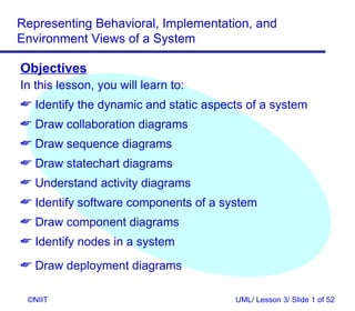
Objectives
In this lesson, you will learn to:
Identify the dynamic and static aspects of a system
Draw collaboration diagrams
Draw sequence diagrams
Draw statechart diagrams
Understand activity diagrams
Identify software components of a system
Draw component diagrams
Identify nodes in a system
Draw deployment diagrams
©NIIT UML/ Lesson 3/ Slide 1 of 52
- 2. Representing Behavioral, Implementation, and
Environment Views of a System
Dynamic and Static Aspects of a System
A system comprises of processes
Processes are realizations of methods or behaviors
Predefined methods constitute the static aspect of the
system
Methods, when applied in a real-life scenario to
accomplish a particular task, constitute the dynamic
aspect of the system
The behavioral view depicts the dynamic aspect of the
software system model
©NIIT UML/ Lesson 3/ Slide 2 of 52
- 3. Representing Behavioral, Implementation, and
Environment Views of a System
Types of Diagrams
Collaboration Diagrams
Sequence Diagrams
Statechart Diagrams
Activity Diagrams
©NIIT UML/ Lesson 3/ Slide 3 of 52
- 4. Representing Behavioral, Implementation, and
Environment Views of a System
Types of Diagrams (Contd.)
Collaboration Diagrams - Represent the interaction
between classes and their associations
Sequence Diagrams - Describe the interaction
between classes and their associations
Statechart Diagrams
Describe the behavior of a class when accessed
by external processes or entities
Depict the states and responses of a class while
performing an action
©NIIT UML/ Lesson 3/ Slide 4 of 52
- 5. Representing Behavioral, Implementation, and
Environment Views of a System
Types of Diagrams (Contd.)
Activity Diagrams
Depict the activities of a class
Describe the behavior of a class when accessed
by internal processes or entities
©NIIT UML/ Lesson 3/ Slide 5 of 52
- 6. Representing Behavioral, Implementation, and
Environment Views of a System
Collaboration Diagrams
Are used to:
Understand the messages that are exchanged
between classes
Depict relationships between classes and their
associations
©NIIT UML/ Lesson 3/ Slide 6 of 52
- 7. Representing Behavioral, Implementation, and
Environment Views of a System
Collaboration Diagrams (Contd.)
Diagrammatic Conventions for Drawing Collaboration
Diagrams
Association Role
Sender Class Receiver Class
©NIIT UML/ Lesson 3/ Slide 7 of 52
- 8. Representing Behavioral, Implementation, and
Environment Views of a System
Collaboration Diagrams (Contd.)
List of classes, behaviors, and attributes
Class Behaviors Attributes
- informRegions()
Distribution Manager
- notifyEmployees()
- regionName
Position Vacant - noOfVacancy
- skillsRequired
Regional HR Head (V) - enterVacancyDetails() - regionName
Regional HR Head (O) - regionName
- empCode
- empName
Employee - qualification
- dateOfJoining
- yearsOfExperience
©NIIT UML/ Lesson 3/ Slide 8 of 52
- 9. Representing Behavioral, Implementation, and
Environment Views of a System
Collaboration Diagrams (Contd.)
Association Roles
Specifies the role that a class plays in a
collaboration of classes
Similar to the defined behaviors of the class
The association roles are:
® Enters Bill Details
® Notifies Bill Details
® Calculate Total Amount
® Print Bill
©NIIT UML/ Lesson 3/ Slide 9 of 52
- 10. Representing Behavioral, Implementation, and
Environment Views of a System
Collaboration Diagrams (Contd.)
Message Flows
Classes exchange messages by following defined
association roles. The message flows are:
Enter Bill Details flow from the Clerk to the
BillDetailAcceptor
Validate Bill Details flow from the BillDetailAcceptor
to the TotalAmountCalculator
Calculate Total Amount flow from the
TotalAmountCalculator to the BillPrinter
Print Bill flow from the BillPrinter to the Clerk.
©NIIT UML/ Lesson 3/ Slide 10 of 52
- 11. Representing Behavioral, Implementation, and
Environment Views of a System
Collaboration Diagrams (Contd.)
Collaboration diagram
BillDetailAcceptor
Enter Bill Details
Clerk
Validate Bill Details
TotalAmountCalculator
Calculate Total
Amount
BillPrinter
Print Bill
Clerk
©NIIT UML/ Lesson 3/ Slide 11 of 52
- 12. Representing Behavioral, Implementation, and
Environment Views of a System
Problem Statement 3.D.1
In the internal job postings process, the HR head of the
region where a vacancy exists informs the employees of that
region and other regional HR heads about the vacancy. The
other regional HR heads inform employees by putting up a
notice with the vacancy information.
Draw a collaboration diagram.
©NIIT UML/ Lesson 3/ Slide 12 of 52
- 14. Representing Behavioral, Implementation, and
Environment Views of a System
Solution: (Contd.)
Association Roles
The association roles are:
® Enters vacancy details
® Notifies vacancy details
® Informs vacancy details
©NIIT UML/ Lesson 3/ Slide 14 of 52
- 15. Representing Behavioral, Implementation, and
Environment Views of a System
Solution: (Contd.)
Message Flows
The message flows are:
Vacancy details flow from the Regional HR Head
(V) to the Distribution Manager
Vacancy details flow from the Distribution Manager
to the Employee
Vacancy details flow from the Distribution Manager
to the Regional HR Head (O)
©NIIT UML/ Lesson 3/ Slide 15 of 52
- 16. Representing Behavioral, Implementation, and
Environment Views of a System
Solution: (Contd.)
Collaboration Diagram
Enters Distribution Manager Notifies vacancy
vacancy details details
RHR(V) EMP
Informs vacancy
details
RHR(O)
©NIIT UML/ Lesson 3/ Slide 16 of 52
- 17. Representing Behavioral, Implementation, and
Environment Views of a System
Sequence Diagrams
Show interactions between classes arranged in a time
sequence
Interactions are the message exchanges that take
place between classes to accomplish a specific
purpose
Interactions are associated with use cases and are
depicted by scenarios
©NIIT UML/ Lesson 3/ Slide 17 of 52
- 18. Representing Behavioral, Implementation, and
Environment Views of a System
Sequence Diagrams (Contd.)
In the billing system, the interactions would be in the
following sequence:
The Clerk class interacts with the
BillDetailAcceptor class
The BillDetailAcceptor class interacts with the
TotalAmountCalculator class
The TotalAmountCalculator class interacts with the
BillPrinter class
The BillPrinter class interacts with the Clerk class
©NIIT UML/ Lesson 3/ Slide 18 of 52
- 19. Representing Behavioral, Implementation, and
Environment Views of a System
Diagrammatic Conventions for Drawing
Sequence Diagrams
The Classes are represented by rectangles
Class Name
©NIIT UML/ Lesson 3/ Slide 19 of 52
- 20. Representing Behavioral, Implementation, and
Environment Views of a System
Diagrammatic Conventions for Drawing
Sequence Diagrams (Contd.)
Interactions are represented by dotted lines
Labeled horizontal arrows depict the direction of
message flows between classes
Class Name Class Name
1: message
©NIIT UML/ Lesson 3/ Slide 20 of 52
- 21. Representing Behavioral, Implementation, and
Environment Views of a System
Sequence Diagram
BillDetailAcceptor TotalAmountCalculator BillPrinter
Clerk Clerk
1. Enter Bill Details
2. Validate Bill Details
3. Calculate Total
4. Print Bill
Amount
©NIIT UML/ Lesson 3/ Slide 21 of 52
- 22. Representing Behavioral, Implementation, and
Environment Views of a System
Statechart Diagrams
Statechart diagrams
Lie within the behavioral view of a system
Are drawn only for those classes, which have very
high dynamic behavior within the context of the
system
Represent various entity states and transitions
Describe the behavior of objects when an external
entity initiates a task to be performed by the object
©NIIT UML/ Lesson 3/ Slide 22 of 52
- 23. Representing Behavioral, Implementation, and
Environment Views of a System
Statechart Diagrams (Contd.)
Depicts a situation during the life of an object in
which the object:
® satisfies certain conditions
® performs a certain activity
® waits for an event to occur
Transitions
Describe the relationships between various states
of an object in a system
Are used to model the relationships between
various states of an object
©NIIT UML/ Lesson 3/ Slide 23 of 52
- 24. Representing Behavioral, Implementation, and
Environment Views of a System
Statechart Diagrams Contd.)
Consider the example of the billing system. The
various states of the bill are:
Bill empty
Bill with items
Bill with total amount
Bill closed
Bill printed
©NIIT UML/ Lesson 3/ Slide 24 of 52
- 25. Representing Behavioral, Implementation, and
Environment Views of a System
Diagrammatic Conventions for Drawing
Statechart Diagrams
States are represented by rectangles with rounded
corners
State Name
©NIIT UML/ Lesson 3/ Slide 25 of 52
- 26. Representing Behavioral, Implementation, and
Environment Views of a System
Diagrammatic Conventions for Drawing
Statechart Diagrams (Contd.)
Transitions are represented by arrows between the
states
All transitions must be labeled
Transition Name
State Name State Name
©NIIT UML/ Lesson 3/ Slide 26 of 52
- 27. Representing Behavioral, Implementation, and
Environment Views of a System
Example For Statechart Diagram
Bill Empty
Bill details entered
Bill with Items
Total amount calculated
Bill with Total Amount
Bill closed
Bill closed
Bill printed
Bill printed
©NIIT UML/ Lesson 3/ Slide 27 of 52
- 28. Representing Behavioral, Implementation, and
Environment Views of a System
Activity Diagrams
Are similar to statechart diagrams and use similar
diagrammatic conventions
Action states represent the state of execution of
atomic actions or operations within a system
Every activity can be divided into many
noninterruptible actions called atomic actions
Action flows represent the association between
various action states of an object
Object flows describe the association between action
states and objects
©NIIT UML/ Lesson 3/ Slide 28 of 52
- 29. Representing Behavioral, Implementation, and
Environment Views of a System
Diagrammatic Conventions for Drawing Activity
Diagrams
Action states are represented as shown:
Action State
Action flows are represented as solid paths
Action flows
Action State Action State
©NIIT UML/ Lesson 3/ Slide 29 of 52
- 30. Representing Behavioral, Implementation, and
Environment Views of a System
Diagrammatic Conventions for Drawing Activity
Diagrams (Contd.)
Object flows are represented as dotted lines:
Object
Flow
Object
Action State Action State
©NIIT UML/ Lesson 3/ Slide 30 of 52
- 31. Representing Behavioral, Implementation, and
Environment Views of a System
Activity Diagram
The diagram shows the various bill objects
manipulated by the activities
Bill
Bill details entered
Total amount calculated
Bill closed
Bill printed
©NIIT UML/ Lesson 3/ Slide 31 of 52
- 32. Representing Behavioral, Implementation, and
Environment Views of a System
Implementation View of a System
Depicts various aspects of software system
implementation
® For example:
® the source code structure
® the run-time implementation structure
® configuration management of software
releases
©NIIT UML/ Lesson 3/ Slide 32 of 52
- 33. Representing Behavioral, Implementation, and
Environment Views of a System
Implementation View of a System (Contd.)
Component is a class or a group of classes that help
in performing a well-defined, real-life task,
independent of its surrounding
Component diagrams are used to represent the
implementation view of a system
©NIIT UML/ Lesson 3/ Slide 33 of 52
- 34. Representing Behavioral, Implementation, and
Environment Views of a System
Diagrammatic Conventions for Drawing
Component Diagrams
Components are represented as shown:
Component
Two or more components are depicted in a component
diagram, as shown:
Component one Component two
©NIIT UML/ Lesson 3/ Slide 34 of 52
- 35. Representing Behavioral, Implementation, and
Environment Views of a System
Component Diagram
The diagram given below shows one of the
components of the billing system
Bill Detail
Acceptor
component
©NIIT UML/ Lesson 3/ Slide 35 of 52
- 36. Representing Behavioral, Implementation, and
Environment Views of a System
Problem Statement 3.D.2
In the internal job postings process, the HR head of
region where a vacancy exists informs the employees of
that region and other regional HR heads. The other
regional HR heads inform employees by putting up a
notice with the vacancy information.
Draw the component diagram.
©NIIT UML/ Lesson 3/ Slide 36 of 52
- 38. Representing Behavioral, Implementation, and
Environment Views of a System
Solution: (Contd.)
Component Diagram
The distribution manager class maps to a
component
Distribution Manager
component
©NIIT UML/ Lesson 3/ Slide 38 of 52
- 39. Representing Behavioral, Implementation, and
Environment Views of a System
Environment View of a System
Environment view:
Depicts the physical distribution of various
components used in the system
Is also known as the deployment view
Depicts the nodes that form a part of the physical
hardware requirement for the deployment of the
system
Includes the nodes that represent a system’s
hardware requirement or design of the network in
which the system will be deployed
©NIIT UML/ Lesson 3/ Slide 39 of 52
- 40. Representing Behavioral, Implementation, and
Environment Views of a System
Diagrammatic Conventions for Drawing
Deployment Diagrams
Nodes are represented as three-dimensional cubes
Node
©NIIT UML/ Lesson 3/ Slide 40 of 52
- 41. Representing Behavioral, Implementation, and
Environment Views of a System
Problem Statement 3.D.3
In the internal job postings process, the HR head of a
region where a vacancy exists informs the employees of
that region and other regional HR heads. The other
regional HR heads inform employees by putting up a
notice with the vacancy information.
Draw the deployment diagram.
©NIIT UML/ Lesson 3/ Slide 41 of 52
- 42. Representing Behavioral, Implementation, and
Environment Views of a System
Solution:
Various nodes would be:
The user node, which the user (HR head of the
region where the vacancy exists) uses for entering
the vacancy details
The server node that hosts the application software
The database server node that hosts the database
©NIIT UML/ Lesson 3/ Slide 42 of 52
- 43. Representing Behavioral, Implementation, and
Environment Views of a System
Deployment Diagram for the HR department
User Node Application Database
Server Node Server
Node
©NIIT UML/ Lesson 3/ Slide 43 of 52
- 44. Representing Behavioral, Implementation, and
Environment Views of a System
Example for Deployment Diagram
Consider the billing system example. The nodes
identified are the Application Server Node, the
Database Server Node, the User Node, and the
Printer Node
User Node Application Database
Server Node Server Node
Printer
Node
©NIIT UML/ Lesson 3/ Slide 44 of 52
- 45. Representing Behavioral, Implementation, and
Environment Views of a System
Problem Statement 3.P.1
In response to the vacancy information, employees from
various regions send their applications to the HR head of
the region where the vacancy exists.
©NIIT UML/ Lesson 3/ Slide 45 of 52
- 46. Representing Behavioral, Implementation, and
Environment Views of a System
Problem Statement 3.P.1 (Contd.)
Class Behavior Attribute
- informRegions()
Distribution Manager
- notifyEmployees()
- regionName
Position Vacant - noOfVacancy
- skillsRequired
Regional HR Head (V) - enterVacancyDetails() - regionName
Regional HR Head (O) - regionName
- empCode
- empName
Employee - qualification
- dateOfJoining
- yearsOfExperience
©NIIT UML/ Lesson 3/ Slide 46 of 52
- 47. Representing Behavioral, Implementation, and
Environment Views of a System
Problem Statement 3.P.1 (Contd.)
Use the classes, their behaviors, and their attributes that
you have identified for this part of the internal job
postings process to:
Identify association roles and message flows
Draw the collaboration diagram
©NIIT UML/ Lesson 3/ Slide 47 of 52
- 48. Representing Behavioral, Implementation, and
Environment Views of a System
Problem Statement 3.P.2
In response to the vacancy information, employees from
various regions send their applications to the HR head of
the region where the vacancy exists.
Use the classes, their behaviors, and their attributes that
you have identified for this part of the internal job
postings process to:
Identify various software components
Draw the component diagram
©NIIT UML/ Lesson 3/ Slide 48 of 52
- 49. Representing Behavioral, Implementation, and
Environment Views of a System
Problem Statement 3.P.3
In response to the vacancy information, employees from
various regions send their applications to the HR head of
the region where the vacancy exists.
Identify various nodes of the automated system for this
part of the internal job postings process and draw the
deployment diagram.
©NIIT UML/ Lesson 3/ Slide 49 of 52
- 50. Representing Behavioral, Implementation, and
Environment Views of a System
Summary
In this lesson, you learned that:
Classes exchange messages by following defined
association roles. Message exchanges are also
called message flows.
Collaboration diagrams are used to understand the
messages that are exchanged between classes.
A state depicts a situation during the life of an
object in which the object satisfies certain
conditions, performs certain activity, or waits for
the event to occur.
Transitions depict the relationships between
various states of an object.
©NIIT UML/ Lesson 3/ Slide 50 of 52
- 51. Representing Behavioral, Implementation, and
Environment Views of a System
Summary (Contd.)
Statechart diagrams explain the messages and
attributes that the classes in a system must
support to perform a purposeful behavior or
functionality.
A class or a group of classes, which help in
performing a well-defined, real-life task,
independent of its surrounding, is called a
(software) component.
©NIIT UML/ Lesson 3/ Slide 51 of 52
- 52. Representing Behavioral, Implementation, and
Environment Views of a System
Summary (Contd.)
Nodes depict the hardware components of a
system on which software components are
deployed and executed.
©NIIT UML/ Lesson 3/ Slide 52 of 52