SlideShare uma empresa Scribd logo
1 de 14
112
F20358/54321-01/04-10M-IG-Subjecttochange.©BelimoAircontrols(USA),Inc.
LM Series Direct Coupled Actuator
Areas of Application
Small Yet Powerful
q Minimum 35 in-lb torque in a compact package.
For damper areas up to 8 sq-ft*.
®
Torque: 35 in-lb q q q q q q q q q q q q
Power supply : 24 VAC/DC q q q q q q q q q q q q
Brushless DC motor: q q q q
Control signal: on-off q q q q q q q q
floating point q q q q
proportional 2 to 10 VDC q q q q
Feedback signal: 2 to 10 VDC q q
10kΩ feedback potentiometer q
5kΩ feedback potentiometer q
Run time, 95 sec q q q q
Run time, 80 to 110 sec for 0 to 35 in-lb q q q q q
Run time, 25 to 35 sec for 0 to 18 in-lb q q q
Left/Right rotation switch q q q q q q q q q
Angle of rotation limiting (mechanical) q q q q q q q q q q
Angle of rotation limiting (electronic) q q
Plenum rated cable, 18 GA q q q q q q q
Screw terminal strip q q q q q
Manual override push-button q q q q q q q q q q q q
Built-in auxiliary switch q
Installation instructions ......(p. 122–124) General wiring ..............(p. 123)
Start-up and checkout ......(p. 125)
* 4 in-lb/ft2 damper torque loading. Parallel blade. No edge seals.
LM Series – at a glance
LM24-3US(p.114)
LM24-3-TUS(p.114)LM24-TUS(p.118)LM24-SUS(p.118)
LM24US(p.118)
LM24-10PUS(p.118)LM24-5P0-TUS(p.118)LM24-SR-2.0US(p.116)
LM24-SR-T-2.0US(p.116)
LMC24US(p.120)LMC24-SRUS(p.120)LMC24-SR-TUS(p.120)
Rack and pinion type actuator
replaced by direct coupled LM.
Replacement LM24 compatible
with existing control system.
Replacement Belimo
actuator (LM type)
direct couples to VAV
By-Pass damper shaft.
Existing pneumatic
actuator requires linkage.
VAV Units and Small Zone Dampers
Quiet Plus
®
VAV
terminal unit by
Warren Technology
113
F20358/54321-01/04-10M-IG-Subjecttochange.©BelimoAircontrols(USA),Inc.
LM
LISTED
94D5
TEMP. IND &
REG. EQUIP.
UL
q Brushless DC Motor for added accuracy
and controllability.
q Cut labor costs with simple direct coupling.
q Check damper position from a distance with
clear position indication.
q Don’t worry about actuator burn-out.
Belimo is overload-proof throughout rotation.
q Enjoy added flexibility with easy mechanical
stops to adjust angle of rotation.
(LM24-SR-2.0 US has electronic rotation limiting.)
q Consistent running time independent of load.
q Easily accessible manual override push-button
helps you pre-tension damper blades.
q Need to change control direction?
Do it easily with a simple switch.
q 3 ft. plenum rated cable eases installation
(external terminal strip also available)
Bulk Packaging Offers Big
Value for Large Jobs,
Stocking Orders.
LM Series Direct Coupled Actuator
®
The Belimo Difference
q Customer Commitment.
Extensive product range. Competitive project pricing. Application assistance.
Same-day shipments. Free technical support. Five year warranty.
q Low Installation and Life-Cycle Cost.
Easy installation. Accuracy and repeatability.
Low power consumption. No maintenance.
q Long Service Life.
Components tested before assembly. Every product tested before shipment.
20+ years direct coupled actuator design.
A CLOSER LOOK…
©
114
F20358/54321-01/04-10M-IG-Subjecttochange.©BelimoAircontrols(USA),Inc.
Application
For on-off and floating point control of dampers in HVAC sys-
tems. Actuator sizing should be done in accordance with the
damper manufacturer’s specifications. The actuator mounts
directly to the damper operating shaft with a universal V-bolt
clamp assembly.
Operation
The actuator is not provided with and does not require any limit
switches, but is electronically protected against overload. The
angle of rotation is mechanically limited to 95°. When reaching
the damper or actuator end position, the actuator automatically
stops. The gears can be manually disengaged with a button on
the actuator cover. The position of the actuator is indicated by
a visual pointer. The anti-rotation strap supplied with the actua-
tor will prevent lateral movement.
The LM24-3 US and LM24-3-T US actuators use a Brushless
DC motor, which is controlled by an Application Specific
Integrated Circuit (ASIC). The ASIC monitors and controls the
actuator’s rotation and provides a digital rotation sensing (DRS)
function to prevent damage to the actuator in a stall condition.
Accessories
11533 T-type anti-rotation bracket
22065 L-type anti-rotation bracket (included)
ZG-LMSA Shaft adaptor for short shafts
Tool-02 8 mm wrench
LM24-3 (-T) US
On-off/ floating point control, non-spring return, direct coupled, 24 V
Dimensions (All numbers in brackets are metric.)
Torque min. 35 in-lb, for control of damper surfaces up to 8 sq ft.
LM24-3 US
LM24-3-T US
LM24-3 US LM24-3-T US
LISTED
94D5
TEMP. IND &
REG. EQUIP.
UL
®
Technical Data LM24… on-off/floating point
Power supply 24 VAC ± 20% 50/60 Hz 24 VDC ± 10%
Power consumption 2 W
Transformer sizing 3 VA (Class 2 power source)
Electrical connection* 3 ft, 18 GA, UL CL2P plenum cable
Control On-off/Floating point
Overload protection Electronic throughout 0 to 95° rotation
Input impedance 3900Ω
Angle of rotation max 95°, adjust. with mechanical stops
Torque min 35 in-lb [4 Nm], Independent of load
Direction of rotation reversible w/switch CW/CCW
(not on “-T” models)
Position indication clip-on indicator (not on “-T” models)
Running time 95 seconds
Manual override external push button
Humidity 5 to 95% RH, non-condensing
Ambient temperature -22°F to +122°F [-30°C to +50°C]
Storage temperature -40°F to +176°F [-40°C to +80°C]
Housing type NEMA type 2 (-T models NEMA 1)
Housing material rating UL94-5V
Noise level less than 35 dB (A)
Servicing maintenance free
Agency listings UL873 listed, CSA 22.2 No. 24 certified, CE
Quality standard ISO 9001
Weight 1.2 lbs [0.55 kg]
LM24-3-T.1 US
Electrical connection Screw terminal (for 26 to 14 GA wire)
Housing NEMA type 1
Direction of rotation Reverse wires terminals 2 and 3
*Standard cable length is 3 ft [1m]. Optional cable lengths of
6 ft [200m] or 10 ft [300m] are available at additional list price.
©
L
R
20%100%
1
1
0
0
3.47" [88]
4.53" [115]
3.68" [93.5]
0.85"
[21.5]
1.28"
[32.5]
2.56"
[65]
2.32"
[58.9]
1/4" to 5/8" [6 to 16]
1/4" to 7/16" [6 to 11]
D014
115
F20358/54321-01/04-10M-IG-Subjecttochange.©BelimoAircontrols(USA),Inc.
LM
1
3224 VAC Transformer
a open
a closed
The indication of direction
is valid for switch position R.
Blk (1) Common
Red (2) +
Wht (3) +
LM24-3 (-T) US
L R
a
Line
Volts
1
2
324 VAC Transformer
The indication of direction
is valid for switch position CW.
Blk (1) Common
Red (2) +
Wht (3) +
LM24-3 US
CCW CW
Line
Volts
LM24-3 (-T) US
On-off/ floating point control, non-spring return, direct coupled, 24 V
LM24… on-off/floating - Typical Specification:
Control damper actuators shall be electronic direct coupled
type which require no crank arm and linkage. Actuators shall
be UL and CSA listed, have a 5 year warranty, and be man-
ufactured under ISO 9001 International Quality Control
Standards. Actuators shall have Brushless DC motor tech-
nology. Actuators shall have reversing switch and manual
override on the cover, and be protected from overload at all
angles of rotation. If required, actuator will be provided with
screw terminal strip for electrical connections (LM24-3-T US).
Actuators shall be as manufactured by Belimo.
On-off control
Line
Volts
1 Common
2 +
3 +
24 VAC Transformer
LM24-3-T US
6
51
2
Floating point or on-off control of LM24-3-T US
3
2
5
6
1 Provide overload protection and disconnect as required.
Actuators may also be powered by 24 VDC.
Actuators are provided with color coded wires. Wire
numbers are provided for reference.
The LM24-3-T US actuators are provided with a num-
bered screw terminal strip instead of cable.
Switch wires 2 and 3 to change rotation direction of
LM24-3-T US (does not have CW/CCW external switch).
Floating point or on-off control
Bulk packaging
Bulk Pack No. Actuator Type Quantity/Pack
LM24-3.1 US LM24-3 US 32
LM24-3-T.1 US LM24-3-T US 48
®
Notes
T-Type bracket
These are included in the single-actuator
packages and are available
at no extra cost in the bulk
packages upon request.
Part # 11533 (UOM:1)
L-Type anti-rotation bracket.
Included with each bulk
packaged actuator.
W080
W082
W081
To have better control of job site inventory and reduce the
environmental impact of unnecessary packing material.
Part #: 22065 (UOM:1)
12502-00002
(includes 22065: UOM:16)
shipped with bulk pack option.
116
F20358/54321-01/04-10M-IG-Subjecttochange.©BelimoAircontrols(USA),Inc.
LM24-SR (-T) -2.0 US
Proportional control, non-spring return, direct coupled,
24 V, for 2 to 10 VDC and 4 to 20 mA control signal
Application
For proportional modulation of dampers in HVAC systems.
Actuator sizing should be done in accordance with the damper
manufacturer’s specifications. The actuator mounts directly to
the damper operating shaft with a universal V-bolt clamp
assembly. The actuator operates in response to a 2 to 10 VDC
or, with the addition of a 500 Ω resistor, a 4 to 20 mA input sig-
nal from an electronic controller or positioner. A 2 to 10 VDC
feedback signal is provided for position indication or master
slave applications. (Not available on “-T” versions)
The LM24-SR-2.0 US provides an electronic angle of rotation
adjustment to limit the actuators rotation 20% to 100% while still
using the full input signal and feedback control range. (Not
available on LM24-SR-T-2.0 US)
Operation
The anti-rotation strap supplied with the actuator will prevent lat-
eral movement of the actuator. The damper actuator is not pro-
vided with and does not require any limit switches, but is pro-
tected electronically against overload. The angle of rotation is
mechanically limited to 95°. When reaching the damper or actu-
ator end position, the actuator automatically stops. The gears
can be manually disengaged by pressing a button on the actua-
tor cover. The position of the actuator is indicated by a visual
pointer.
The LM24-SR-2.0 US and LM24-SR-T-2.0 US actuators use a
Brushless DC motor, which is controlled by an Application Specific
Integrated Circuit (ASIC). The ASIC monitors and controls the
actuator’s rotation and provides a digital rotation sensing (DRS)
function to prevent damage to the actuator in a stall condition.
Accessories
11533 T-type anti-rotation bracket
22065 L-type anti-rotation bracket (included)
ZG-LMSA Shaft adaptor for short shafts
Tool-02 8 mm wrench
ZG-R01 500Ω resistor for 4 to 20 mA
Dimensions (All numbers in brackets are metric.)
Torque min. 35 in-lb, for control of damper surfaces up to 8 sq ft.
LM24-SR-2.0 US
LM24-SR-T-2.0 US
®
LM24-SR-T-2.0 USLM24-SR-2.0 US
LISTED
94D5
TEMP. IND &
REG. EQUIP.
UL
©
Technical Data LM24-SR-2.0 US
Power supply 24 VAC ± 20% 50/60 Hz
24 VDC ± 10%
Power consumption 2 W
Transformer sizing 4 VA (Class 2 power source)
Electrical connection* LM24-SR-2.0 US: 3 ft, 18 GA, UL
CL2P plenum cable
Overload protection Electronic throughout 0 to 95° rotation
Operating range Y 2 to 10 VDC, 4 to 20 mA
Input impedance 100 kΩ (0.1 mA), 500Ω
Feedback output ‘U’ 2 to 10 VDC (max. 0.7 mA )
(not available on LM24-SR-T-2.0 US
Angle of rotation max 95°, electronically adjustable
20 to 100% on LM24-SR-2.0 US
Torque min 35 in-lb, Independent of load
Direction of rotation reversible with switch CW/CCW
CW = with an increase in voltage
CCW = with an increase in voltage
Position indication clip-on indicator (not on “-T” models)
Running time 95 seconds
Manual override external push button
Humidity 5 to 95% RH, non-condensing
Ambient temperature -22°F to +122°F [-30°C to +50°C]
Storage temperature -40°F to +176°F [-40°C to +80°C]
Housing type NEMA type 2 (-T models Nema type1)
Housing material rating UL 94-5V
Noise level less than 35 dB (A)
Servicing maintenance free
Agency listings UL 873 listed, CSA 22..2 No. 24 certified, CE
Quality standard ISO 9001
Weight 1.2 lbs [0.55 kg]
LM24-SR-T-2.0.1 US
Electrical connection Screw terminals (for 26 to 14 GA wire)
Angle of rotation max 95°, adjust. with mechanical stops
Housing NEMA type 1
Feedback No feedback with the LM24-SR-T-2.0 US
*Standard cable length is 3 ft [1m]. Optional cable lengths of
6 ft [200m] or 10 ft [300m] are available at additional list price.
L
R
20%100%
1
1
0
0
3.47" [88]
4.53" [115]
3.68" [93.5]
0.85"
[21.5]
1.28"
[32.5]
2.56"
[65]
2.32"
[58.9]
1/4" to 5/8" [6 to 16]
1/4" to 7/16" [6 to 11]
D014
117
F20358/54321-01/04-10M-IG-Subjecttochange.©BelimoAircontrols(USA),Inc.
LM
LM24-SR (-T) -2.0 US
Proportional control, non-spring return, direct coupled,
24 V, for 2 to 10 VDC and 4 to 20 mA control signal
1 2724 VAC Transformer
Blk (1) Common
Red (2) + Hot
Wht (3) Y 2 to 10V Input
Grn (5) U 2 to 10V Output
LM24-SR-2.0 US
CCW CW
Line
Volts
2 to 10 VDC
Control Signal
2 to 10 VDC
Feedback Signal
(–)
(+)
(–)
(+)
6
1 2724 VAC Transformer
Blk (1) Common
Red (2) + Hot
Wht (3) Y 2 to 10V Input
Grn (5) U 2 to 10V Output
LM24-SR-2.0 US
CCW CW
Line
Volts
4 to 20 mA
Control Signal
2 to 10 VDC
Feedback Signal
(–)
(+)
(–)
(+)
6
8
Ω
500Ω
2 to 10 VDC control of LM24-SR-2.0 US
4 to 20 mA control of LM24-SR-2.0 US with 2 to 10 VDC
feedback output
2
4
5
6
7
8
1 Provide overload protection and disconnect as required.
Actuators are provided with color coded wires. Wire
numbers are provided for reference.
The LM24-SR-T-2.0 US is provided a screw terminal
instead of cable.
The LM24-SR-T-2.0 US does not have feedback.
Connect actuator common (Wire 1) to Negative (–) leg
of control circuits only.
Actuators may also be powered by 24 VDC.
A 500Ω resistor (ZG-R01) must be added for 4 to 20
mA control.
1 4724 VAC Transformer
1 Common
2 + Hot
3 Y 2 to 10V Input
LM24-SR-T-2.0 US
CCW CW
Line
Volts
4 to 20 mA
Control Signal
w/500Ω resistor
(–)
(+)
6
8
Ω
500Ω
2 to 10 VDC
5
2 to 10 VDC and 4 to 20 mA control of LM24-SR-T-2.0 US
®
Bulk packaging LM24SR-2.0 US and LM24SR-T-2.0 US
LM24-SR (-T) 2.0 US - Typical Specification:
Control damper actuators shall be electronic direct coupled
type which require no crank arm and linkage. Actuators shall
be UL and CSA listed, have a 5 year warranty, and be man-
ufactured under ISO 9001 International Quality Control
Standards. Actuators shall have Brushless DC motor.
Actuators shall have reversing switch and gear disengage-
ment button on the cover, and be electronically protected from
overload at all angles of rotation. Actuators shall respond to 2
to 10VDC output relative to position regardless of the amount
of damper rotation. A 2 to 10 VDC feedback signal shall be
provided for position indication or master-slave applications.
Actuators shall be as manufactured by Belimo.
An electronic angle of rotation adjustment shall be provided to
reduce the actuators rotation from 100 to 20% while still using
the full input signal and feedback control range. (LM24-SR US)
If required, actuator will be provided with screw terminal strip for
electrical connections (LM24-SR-T US).
Notes
Bulk Pack No. Actuator Type Quantity/Pack
LM24-SR-2.0.1 US LM24-SR-2.0 US 32
LM24-SR-T.-2.0.1 US LM24-SR-T-2.0 US 48
T-Type bracket
These are included in the single-actuator
packages and are available
at no extra cost in the bulk
packages upon request.
Part # 11533 (UOM:1)
W083W084
W085
To have better control of job site inventory and reduce the
environmental impact of unnecessary packing material.
L-Type anti-rotation bracket.
Included with each bulk
packaged actuator.
Part #: 22065 (UOM:1)
12502-00002
(includes 22065: UOM:16)
shipped with bulk pack option.
118
F20358/54321-01/04-10M-IG-Subjecttochange.©BelimoAircontrols(USA),Inc.
Application
For on-off control of dampers in HVAC systems. Actuator siz-
ing should be done in accordance with the damper manufac-
turer’s specifications. The actuator mounts directly to the
damper operating shaft with a universal V-bolt clamp assem-
bly.
Operation
The actuator is not provided with and does not require any
limit switches, but is electronically protected against overload.
The angle of rotation is mechanically limited to 95°. When
reaching the damper or actuator end position, the actuator
automatically stops. The gears can be manually disengaged
with a button on the actuator cover. The position of the actua-
tor is indicated by a visual pointer. The anti-rotation strap sup-
plied with the actuator will prevent lateral movement.
Accessories
LM-P T-type anti-rotation bracket
ZG-LMSA Shaft adaptor for short shafts
Tool-02 8 mm wrench
LM24 (-T) US
On-off control, non-spring return, direct coupled, 24 V
Torque min. 35 in-lb, for control of damper surfaces up to 8 sq ft.
LM24 US
LM24-S US
LM24-10P US
LM24-5P0-T US
LM24-T US
LM24-S US LM24-T US
LISTED
94D5
TEMP. IND &
REG. EQUIP.
UL
Technical Data LM24… on-off/floating point
Power supply 24 VAC ± 20% 50/60 Hz 24 VDC ± 10%
Power consumption 2 W
Transformer sizing 3 VA (Class 2 power source)
Electrical connection* 3 ft, 18 GA, UL CL2P plenum cable
Control On-off
Overload protection Electronic throughout 0 to 95° rotation
Angle of rotation max 95°, adjust. with mechanical stops
Torque min 35 in-lb [4 Nm]
Direction of rotation reversible w/switch L/R (not on “-T” models)
Position indication clip-on indicator (not on “-T” models)
Running time 80 to 110 sec. for 0 to 35 in-lb
Manual override external push button
Humidity 5 to 95% RH, non-condensing
Ambient temperature -22°F to +122°F [-30°C to +50°C]
Storage temperature -40°F to +176°F [-40°C to +80°C]
Housing type NEMA type 2 (-T models NEMA 1)
Housing material rating UL94-5V
Noise level less than 35 dB (A)
Servicing maintenance free
Agency listings UL 873 listed, CSA C22.2 No.24 certified, CE
Quality standard ISO 9001
Weight 1.2 lbs [0.55 kg]
LM24-S US
Control On-off
Auxiliary switch Adj. 0° to 95°, SPDT 6 A (2.5A) @ 24 VAC
LM24-10P US
Control On-off/Floating point
Feedback 10 kΩ, 1W potentiometer
LM24-5P0-T.1 US (bulk pack only)
Control On-off/Floating point
Feedback 5 kΩ, 1W potentiometer
Housing NEMA type 1
Direction of rotation Reverse wires terminals 2 and 3
LM24-T.1 US (bulk pack only)
Control On-off
Electrical connection Screw terminal (for 26 to 14 GA wire)
Housing NEMA type 1
Direction of rotation Reverse wires terminals 2 and 3
*Standard cable length is 3 ft [1m]. Optional cable lengths of
6 ft [200m] or 10 ft [300m] are available at additional list price.
®
Dimensions (All numbers in brackets are metric.)
1
1
0
0
3.47" [88]
4.53" [115]
3.68" [93.5]
0.85"
[21.5]
1.28"
[32.5]
2.56"
[65]
2.32"
[58.9]
1/4" to 5/8" [6 to 16]
1/4" to 7/16" [6 to 11]
D015
119
F20358/54321-01/04-10M-IG-Subjecttochange.©BelimoAircontrols(USA),Inc.
LM
1 5 3224 VAC Transformer
a open
a closed
The indication of direction
is valid for switch position R.
Blk (1) Common
Red (2) +
Wht (3) +
LM24 -T US
LM24 (-S) US
LM24-10P US
L R
a
Line
Volts
1
2
3
4
24 VAC Transformer
The indication of direction
is valid for switch position R.
Blk (1) Common
Red (2) +
Wht (3) +
LM24-10P US
L R
Line
Volts
LM24-S US
S1
S2
S3
NC
NO
0° to 95°
LM24 (-T) US
On-off control, non-spring return, direct coupled, 24 V
LM24… on-off - Typical Specification:
Control damper actuators shall be electronic direct coupled type
which require no crank arm and linkage. Actuators shall be UL
and CSA listed, have a 5 year warranty, and be man-ufactured
under ISO 9001 International Quality Control Standards.
Actuators shall have reversing switch and manual override on
the cover, and be protected from overload at all angles of rota-
tion. If required, actuator will be provided with screw terminal strip
for electrical connections (LM24-T US and LM24-5P0-T US). If
required, one adjustable SPDT auxiliary switch shall be provided
(LM24-S US). If required, actuators shall be provided with a built-
in 10 kΩ feedback potentiometer (LM24-10P US) or 5kΩ (LM24-
5P0-T) for use in modulating (floating point) applications.
Actuators shall be as manufactured by Belimo.
On-off control
Line
Volts
1 Common
2 +
3 +
24 VAC Transformer
LM24-5P0-T US
6
4
51
2
3
LM24-10P US
LM24-5P0-T US
0
10/5
10kΩ/5kΩ
Feedback
potentiometer
7
5
4
7
Org (P1)
Blue (P2)
Yel (P3)
Floating point or on-off control
Feedback potentiometer wiring for LM24-10P US and
LM24-5P0-T US
Auxiliary switch wiring for LM24-S US
3
2
4
5
6
7
1 Provide overload protection and disconnect as required.
Actuators may also be powered by 24 VDC.
Actuators are provided with color coded wires. Wire
numbers are provided for reference.
For position indication, the LM24-10P US is provided with
a 10 kΩ feedback potentiometer and the LM24-5P0-T US
is provided with a 5 kΩ feedback potentiometer.
The LM24-T US and LM24-5P0-T US are provided with
a numbered screw terminal strip instead of cable.
Switch wires 2 and 3 to change rotation direction of
LM24-T US and LM24-5P0-T US (does not have L/R
external switch).
Value based on resistance between (P1) and (P2).
indicates direction of rotation of actuator.
Floating point or on-off control
Bulk packaging LM24 on-off/floating
Bulk Pack No. Actuator Type Quantity/Pack
LM24.1 US LM24 US 32
LM24-T.1 US LM24-T US 48
LM24-5P0-T.1 US LM24-5P0-T US 48
L-Type anti-rotation bracket. Included with
each actuator.
Part #: 22065
Notes
®
W086
W089
W087W088
W090
120
F20358/54321-01/04-10M-IG-Subjecttochange.©BelimoAircontrols(USA),Inc.
Application
For on-off control of dampers in HVAC systems (LMC24 US).
For proportional modulation of dampers in HVAC systems
(LMC24-SR-T US). Actuator sizing should be done in accor-
dance with the damper manufacturer’s specifications. The
actuator mounts directly to the damper operating shaft with
a universal V-bolt clamp assembly.
The LMC24-SR-T US actuator operates in response to a 2 to 10
VDC or, with the addition of a 500 Ω resistor, a 4 to 20 mA input
signal from an electronic controller or positioner. A 2 to 10 VDC
feedback signal is provided for position indication or master
slave applications. The LMC24-SR US provides an electronic
angle of rotation adjustment (not available in the LMC24-SR-T US) to
limit the actuators rotation 20% to 100% while still using the full
input signal and feedback control range.
Operation
The actuator is not provided with and does not require any limit
switches, but is electronically protected against overload. The
angle of rotation is mechanically limited to 95°. When reaching
the damper or actuator end position, the actuator automatically
stops. The gears can be manually disengaged with a button on
the actuator cover. The position of the actuator is indicated by a
visual pointer. The anti-rotation strap supplied with the actuator
will prevent lateral movement.
Accessories
LM-P T-type anti-rotation bracket
IRM-100 Input scaling module (For LMC24-SR-T US only)
ZG-LMSA Shaft adaptor for short shafts
PTA-250 Pulse width modulating interface
(For LMC24-SR-T US only)
SGA24 Min. and/or manual positioner in NEMA 4 housing
(For LMC24-SR-T US only)
SGF24 Min. and/or manual positioner for flush panel mount
(For LMC24-SR-T US only)
Tool-02 8 mm wrench
ZAD24 Digital position indication (For LMC24-SR-T US only)
ZG-R01 500Ω resistor for 4 to 20 mA
(For LMC24-SR-T US only)
LMC24 (-SR) (-T) US
Non-spring return, direct coupled, 24 V, 25 to 35 sec. running time
Torque min. 18 in-lb, for control of damper surfaces up to 4.5 sq ft.
LMC24 US (on/off)
LMC24-SR US (proportional)
LMC24-SR-T US (proportional)
LMC24 US LMC24-SR US
LISTED
94D5
TEMP. IND &
REG. EQUIP.
UL
®
Technical Data LMC24 (-SR) US…
Power supply 24 VAC ± 20% 50/60 Hz 24 VDC ± 10%
Power consumption LMC24 US 2.0 W
LMC24-SR (-T) US 2.5 W
Transformer sizing LMC24 US 3 VA
LMC24-SR (-T) US 4 VA
Electrical connection 3 ft, 18 GA, UL CL2P plenum cable
Control On-off (LMC24 US)
Overload protection Electronic throughout 0 to 95° rotation
Angle of rotation max 95°, adjust. with mechanical stops
(LMC24 US), electronically adjustable
20 to 100% on LMC24-SR US only
Torque min 18 in-lb [2 Nm]
Operating range Y 2 to 10 VDC, 4 to 20 mA (LMC24-SR (-T) US)
Input impedance 100 kΩ (0.1 mA), 500Ω (LMC24-SR (-T) US)
Feedback output ‘U’ 2 to 10 VDC (max. 0.7 mA )
(LMC24-SR-T US)
Direction of rotation reversible with switch “CCW-CW”
LMC24-SR-T US:
CW with a decrease in voltage
CCW with a decrease in voltage
Position indication clip-on indicator
Running time 25 to 35 sec. for 0 to 18 in-lb
Manual override external push button
Humidity 5 to 95% RH, non-condensing
Ambient temperature -22°F to +122°F [-30°C to +50°C]
Storage temperature -40°F to +176°F [-40°C to +80°C]
Housing type NEMA type 2
Housing material rating UL94-5V
Noise level less than 35 dB (A)
Servicing maintenance free
Agency listings UL 873 listed, CSA C22.2 No.24 certified, CE
Quality standard ISO 9001
Weight 1.2 lbs [0.55 kg]
LMC24-SR-T US
Electrical connection Screw terminals (for 26 to 14 GA wire)
Angle of rotation max 95°, adjust. with mechanical stops
Housing NEMA type 1
Feedback No feedback with the LMC24-SR-T US
Note: Actuators do not have Brushless DC Motor
Dimensions (All numbers in brackets are metric.)
1
1
0
0
3.47" [88]
4.53" [115]
3.68" [93.5]
0.85"
[21.5]
1.28"
[32.5]
2.56"
[65]
2.32"
[58.9]
1/4" to 5/8" [6 to 16]
1/4" to 7/16" [6 to 11]
D015
121
F20358/54321-01/04-10M-IG-Subjecttochange.©BelimoAircontrols(USA),Inc.
LM
1
3224 VAC Transformer
a open
a closed
The indication of direction
is valid for switch position CW.
Blk (1) Common
Red (2) +
Wht (3) +
LMC24 US
CCW CW
a
Line
Volts
LMC24 (-SR) (-T) US
Non-spring return, direct coupled, 24 V, 25 to 35 sec. running time
LMC24… - Typical Specification:
Control damper actuators shall be electronic direct coupled
type which require no crank arm and linkage. Actuators shall
be UL and CSA listed, have a 5 year warranty, and be man-
ufactured under ISO 9001 International Quality Control
Standards. Actuators shall have reversing switch and manual
override on the cover, and be protected from overload at all
angles of rotation. Actuator shall have a nominal running time
of 30 seconds for 95° rotation. Proportional actuators shall
respond to 2 to 10VDC output relative to position regardless of
the amount of damper rotation. A 2 to 10 VDC feedback sig-
nal shall be provided for position indication or master-slave
applications. An electronic angle of rotation adjustment
(LMC24-SR US only) shall be provided to reduce the actuators
rotation from 100 to 20% while still using the full input signal
and feedback control range. Actuators shall be as manufac-
tured by Belimo.
On-off control
3
2
4
5
6
1 Provide overload protection and disconnect as required.
Actuators may also be powered by 24 VDC
Actuators are provided with color coded wires. Wire
numbers are provided for reference.
Connect actuator common (Wire 1) to Negative (–) leg
of control circuits only.
A 500Ω resistor (ZG-R01) must be added for 4 to 20 mA
control.
LMC24-SR-T US does not have a cable. Numbers
shown are terminal numbers.
L-Type anti-rotation bracket. Included with
each actuator.
Part #: 22065
®
Notes
1 3224 VAC Transformer
Blk (1) Common
Red (2) + Hot
Wht (3) Y 2 to 10V Input
Grn (5) U 2 to 10V Output
LMC24-SR (-T) US
CCW CW
Line
Volts
2 to 10 VDC
Control Signal
2 to 10 VDC
Feedback Signal
(–)
(+)
(–)
(+)
4
6
1 3224 VAC Transformer
Blk (1) Common
Red (2) + Hot
Wht (3) Y 2 to 10V Input
Grn (5) U 2 to 10V Output
LMC24-SR (-T) US
CCW CW
Line
Volts
4 to 20 mA
Control Signal
2 to 10 VDC
Feedback Signal
(–)
(+)
(–)
(+)
4
65
Ω
500Ω
2 to 10 VDC control of LMC24-SR (-T) US
4 to 20 mA control of LMC24-SR (-T) US with 2 to 10 VDC
feedback output
W151
W153W154
122
F20358/54321-01/04-10M-IG-Subjecttochange.©BelimoAircontrols(USA),Inc.
Preliminary steps
1. Belimo actuators should be mounted indoors in dry, relatively clean environment free from corrosive fumes. If the actuator is to
be mounted outdoors, a protective enclosure must be used to shield the actuator. (See Belimo Mechanical Accessories Doc. 5.2)
2. For new construction work, order dampers with extended shafts. Instruct the installing contractor to allow space for mounting and
service of the Belimo actuator on the shaft.
3. The LM Series actuator requires a minimum shaft length of 1.5”.
Use the ZG-LMSA for short shaft installations on 1/2” diameter shafts.
Installation Instructions
Quick-mount visual instructions
®
1. Turn damper blade to its fully closed position.
2. With manual override button depressed, rotate actuator
clamp to about 1/16” - 1/8” between actuator stop and
clamp, depending on damper seal design. Slide actuator
over shaft and finger-tighten nuts.
3. Slide anti-rotation bracket up under actuator engaging cen-
ter cut-out on actuator back. Secure bracket with self-tap-
ping screws. Tighten the two nuts on the universal clamp with
8 mm wrench, 3-5 ft-lb torque. (On dampers with edge seals,
actuator will compress damper blades when reaching end posi-
tion for air-tight damper.)
4. Adjust end stops, if required.
1
2 3
4
L-bracket
L-bracket
min. 1.5” [38]
Dimensions (All numbers in brackets are metric.)
WARNING The wiring technician must be trained and experi-
enced with electronic circuits. Disconnect power supply before
attempting any wiring connections or changes. Make all con-
nections in accordance with wiring diagrams and follow all
applicable local and national codes. Provide disconnect and
overload protection as required. Use copper, twisted pair,
conductors only.
Always read the controller manufacturer's installation liter-
ature carefully before making any connections. Follow all
instructions in this literature. If you have any questions, contact
the controller manufacturer and/or Belimo.
Transformer(s)
The LM Series actuators require a 24 VAC class 2 transformer
and draw a maximum of 4 VA. The actuator enclosure cannot
be opened in the field, there are no parts or components to be
replaced or repaired.
– EMC directive: 89/336/EEC
– Software class A: Mode of operation type 1
– Low voltage directive: 73/23/EEC
CAUTION: It is good practice to power electronic or digital con-
trollers from a separate power transformer than that used for
actuators or other end devices. The power supply design in
our actuators and other end devices use half wave rectification.
Some controllers use full wave rectification. When these two
different types of power supplies are connected to the same
power transformer and the DC commons are connected togeth-
er, a short circuit is created across one of the diodes in the full
wave power supply, damaging the controller. Only use a single
power transformer to power the controller and actuator if you
know the controller power supply uses half wave rectification.
Multiple actuators, one transformer
Multiple actuators may be powered from one transformer pro-
vided the following rules are followed:
1. The TOTAL current draw of the actuators (VA rating) is less
than or equal to the rating of the transformer.
2. Polarity on the secondary of the transformer is strictly fol-
lowed. This means that all No. 1 wires from all actuators
are connected to the common leg on the transformer and all
No 2 wires from all actuators are connected to the hotleg.
Mixing wire No. 1 & 2 on one leg of the transformer will
result in erratic operation or failure of the actuator and or
controls.
Multiple actuators, multiple transformers
Multiple actuators positioned by the same control signal may be
powered from multiple transformers provided the following rules
are followed:
1. The transformers are properly sized.
2. All No. 1 wires from all actuators are tied together and tied
to the negative leg of the control signal. See wiring diagram.
Wire length for LM Series actuators
Keep power wire runs below the limits listed in the Fig. 1. If
more than one actuator is powered from the same wire run,
divide the allowable wire length by the number of actuators to
determine the maximum run to any single actuator.
Maximum wire length:
Wire Size Max. Feet. Wire Size Max. Feet
16 Ga 1225 Ft. 20 Ga 400 Ft
18 Ga 725 Ft. 22 Ga 200 Ft
Fig. 1
Example for LM… US: 3 actuators, 18 Ga wire
725 Ft ÷ 3 Actuators = 241.6 Ft. Maximum wire run.
Wire Type and Wire Installation Tips
For most installations, 18 or 16 Ga. cable works well with the
LM24 type actuators. Use code approved wire nuts, terminal
strips or solderless connectors where wires are joined. It is
good practice to run control wires unspliced from the actuator
to the controller. If splices are unavoidable, make sure the
splice can be reached for possible maintenance. Tape and/or
wire tie the splice to reduce the possibility of the splice being
inadvertently pulled apart.
LM Series Actuators with Terminal Strip
LM…-T actuators feature an external screw terminal strip on
the top of the actuator housing (instead of cable). Connections
are numbered and a wiring schematic is shown next to the ter-
minal strip. The terminals are designed for 26 to 14 GA wire.
Overload protection
All Belimo actuators are electronically protected against over-
load. In the LM series an electronic circuit maintains the cur-
rent at a level which will not damage the motor while providing
adequate holding torque.
Installation Instructions
General Wiring
123
F20358/54321-01/04-10M-IG-Subjecttochange.©BelimoAircontrols(USA),Inc.
LM
®
0 1
Manual Override
A button on the actuator cover disengages the gear train so the
damper shaft can be moved manually. Release the button and the
gear train is re-engaged.
Use the manual override to test the installation without
power. For tight shut-off the damper should close with 5°
of actuator stroke left.
0 1
Gear release
button
AF
124
F20358/54321-01/04-10M-IG-Subjecttochange.©BelimoAircontrols(USA),Inc.
0 1
Adjust angle-of-rotation in steps of 2.5°
Installation Instructions
Feature Operation
Mechanical Angle of Rotation Limiting (LM Series, On-Off/Floating and LM24-SR-T-2.0 US)
The adjustable stops are needed when there is no damper stop
or if you want the damper to halt rotating before it reaches its
stops. The LM actuator can be indefinitely stalled in any posi-
tion without harm.
1. Loosen the two end stops with a No. 2 Phillips head screwdriv-
er being careful not to unscrew the captive nut under the slot.
2. Move the stops (in 2.5° steps) to the desired position and re-
tighten the screws.
LM actuators have a reversing switch on the cover labeled “CW-
CCW”. Switch position indicates start point. For the LM24-SR (-T)
2.0 US, with the switch in position “CW”, the actuator rotates clock-
wise with an increase in voltage or current. With the switch in posi-
tion “CCW”, the actuator rotates counterclockwise with an increase
in voltage or current.
The LM24-3-T US does not have a switch. They rotate clock-
wise when power is applied to wire #3, and counterclockwise
when power is applied to wire #2.
During checkout, the switch position can be temporarily
reversed and the actuator will reverse its direction. This allows
the technician a fast and easy way to check the actuator opera-
tion without having to switch wires or change settings on the
thermostat. When the check-out is complete, make sure the
switch is placed back to its original position.
CW
CCW
0 1
CW
CCW
0 1
10 VDC2 VDC 2 VDC10 VDC
Direction of rotation switch. Position indicates start point.
Electronic Angle of Rotation Limiting (LM24-SR-2.0 US)
With the LM24-SR-2.0 US proportional actuator, you can
adjust the angle of rotation (95°) anywhere between 20% and
100% using an external adjustment. A potentiometer limits
rotation while allowing the full control input and feedback range
(2 to 10 VDC), providing higher control resolution within the lim-
ited angle of rotation.
CCW
0 1
CW
CW
CCW
2 VDC
10 VDC
45°/50% Limit
Feedback signal will also
be adjusted 2 to 10 VDC
0 1
2 VDC
10 VDC
45°/50% Limit
0 1
20% 100%
100%20%
Limitationsetat50%
Angleofrotation=45°
Controlsignal=10VDC
Direction of Rotation Switch (All LM except LM24-3-T US)
®
125
F20358/54321-01/04-10M-IG-Subjecttochange.©BelimoAircontrols(USA),Inc.
LM
®
Procedure
Control signal is applied to actuator.
Check power wiring. Correct any
problems. See Note 1.
Turn reversing switch to the correct
position.
Make sure the control signal positive
(+) is connected to Wire No 3 and
control signal negative (-) is connect-
ed to wire No. 1. Most control prob-
lems are caused by reversing these
two wires. Verify that the reversing
switch is all the way CCW or CW.
Check input signal with a digital volt
meter (DVM). Make sure the input is
within the range of the actuator. For
LM24SR (-T) US this is 0 to 10 VDC or
0 to 20 mA.
Note: The input signal must be above
the 2 VDC or 4 mA to have the actua-
tor move.
Use the manual override button to
move the damper by hand from fully
closed to fully open.
Check damper torque requirement.
Actuator works properly. Test con-
troller by following controller manu-
facturer's instructions.
Expected Response
Actuator will move to its “Control
Signal” position.
Power supply rating should be ≥
the total power requirement of
the actuator(s). Minimum volt-
age of 19.2 VAC or 21.6 VDC.
Actuator will move to its “Control
Signal” position.
Drives to “Control Signal” posi-
tion
Input voltage or current should
be ±1% of what controller's
adjustment or programming indi-
cate.
Damper will go from fully closed
to fully open.
Torque requirement is ≤ actua-
tor’s minimum torque.
Gives Expected
Response
Go To Step…
Actuator operates
properly
Step 8
Power wiring correct-
ed, actuator begins
to drive
Step 1
Actuator operates
properly.
Step 8
Actuator operates
properly.
Step 8
Controller output
(actuator input) is
correct. Input
Polarity Correct.
Step 6
Damper moves
properly
Step 7
Defective Actuator.
Replace Actuator -
See Note 2
Does Not Give
Expected Response
Go To Step…
No response at all
Step 2
Operation is
reversed
Step 3
Does not drive
toward "Control
Signal Position"
Step 4
Power wiring
corrected, actuator
still does not drive
Step 4
Does not drive
toward “Control
Signal Position”
Step 4
Step 5
Reprogram, adjust
repair or replace
controller as needed.
Step 1
Find cause of
damper jam and
repair.
Step 1
Recalculate actuator
requirement and
correct installation.
Step
1.
2.
3.
4.
5.
6.
7.
8.
Note 1 Check that the transformer(s) are sized properly.
• If a common transformer is used, make sure that polarity is observed on the secondary. This means connect all No. 1
wires to one leg of the transformer and all No. 2 wires to the other leg of the transformer.
• If multiple transformers are used with one control signal, make sure all No. 1 wires are tied together and tied to control
signal negative (-).
• Controllers and actuators must have separate 24 VAC/VDC power sources.
Note 2 If failure occurs within 5 years from original installation date, notify Belimo and give details of the application.
LM24-SR (-T) 2.0 US Electrical check-out procedure
Startup and Checkout

Mais conteúdo relacionado

Mais procurados

Manual valvulas on off.pdf 2.
Manual valvulas on off.pdf   2.Manual valvulas on off.pdf   2.
Manual valvulas on off.pdf 2.gaby310
 
Diseño mecanico de intercambiadores
Diseño mecanico de intercambiadoresDiseño mecanico de intercambiadores
Diseño mecanico de intercambiadoresWilly Orosco Mariscal
 
Bobcat 873 f series skid steer loader parts catalogue manual (sn 5142 11001 ...
Bobcat 873 f series skid steer loader parts catalogue manual (sn 5142 11001  ...Bobcat 873 f series skid steer loader parts catalogue manual (sn 5142 11001  ...
Bobcat 873 f series skid steer loader parts catalogue manual (sn 5142 11001 ...fjjkskekfsmem
 
David gimenez revista
David gimenez revistaDavid gimenez revista
David gimenez revistaucla
 
Surge Control for Parallel Centrifugal Compressor Operations
Surge Control for Parallel Centrifugal Compressor OperationsSurge Control for Parallel Centrifugal Compressor Operations
Surge Control for Parallel Centrifugal Compressor OperationsVijay Sarathy
 
Cooling and heating load calculations tide load4z
Cooling and heating load calculations tide load4zCooling and heating load calculations tide load4z
Cooling and heating load calculations tide load4zTin Arboladura
 
Control valve Working and Types with Parts. Terms use in Control Valve
Control valve Working and Types with Parts. Terms use in Control ValveControl valve Working and Types with Parts. Terms use in Control Valve
Control valve Working and Types with Parts. Terms use in Control ValveInstrumentation Knowledge
 
FUNDAMENTAL OF VALVE DESIGN
FUNDAMENTAL OF VALVE DESIGN FUNDAMENTAL OF VALVE DESIGN
FUNDAMENTAL OF VALVE DESIGN MOHAMMAD ATIF ALI
 
Tabela aplicação compressores tecunseh
Tabela aplicação compressores tecunsehTabela aplicação compressores tecunseh
Tabela aplicação compressores tecunsehmanodorosa
 
Tank Control Systems LNG.PDF
Tank Control Systems LNG.PDFTank Control Systems LNG.PDF
Tank Control Systems LNG.PDFAxel Proc
 
Coleccion tablas graficas_ifc
Coleccion tablas graficas_ifcColeccion tablas graficas_ifc
Coleccion tablas graficas_ifcFelipe Ledezma
 
Cooling load calculations and principles
Cooling load calculations and principlesCooling load calculations and principles
Cooling load calculations and principlesDheiy Myth
 
096500-3091 explodido, lista de peças e plano bomba denso
096500-3091 explodido, lista de peças e plano bomba denso096500-3091 explodido, lista de peças e plano bomba denso
096500-3091 explodido, lista de peças e plano bomba densoJunior Iung
 
Boiler doc 06 control valve & actuator
Boiler doc 06   control valve & actuatorBoiler doc 06   control valve & actuator
Boiler doc 06 control valve & actuatorMars Tsani
 
Instalación de aire acondicionado
Instalación de aire acondicionadoInstalación de aire acondicionado
Instalación de aire acondicionadoIo pb
 
Paso para ajuste y verificacion de una valvula de control
Paso para ajuste y verificacion de una valvula de controlPaso para ajuste y verificacion de una valvula de control
Paso para ajuste y verificacion de una valvula de controlEsteban Casanova de la Hoz
 

Mais procurados (20)

Manual valvulas on off.pdf 2.
Manual valvulas on off.pdf   2.Manual valvulas on off.pdf   2.
Manual valvulas on off.pdf 2.
 
Diseño mecanico de intercambiadores
Diseño mecanico de intercambiadoresDiseño mecanico de intercambiadores
Diseño mecanico de intercambiadores
 
Bobcat 873 f series skid steer loader parts catalogue manual (sn 5142 11001 ...
Bobcat 873 f series skid steer loader parts catalogue manual (sn 5142 11001  ...Bobcat 873 f series skid steer loader parts catalogue manual (sn 5142 11001  ...
Bobcat 873 f series skid steer loader parts catalogue manual (sn 5142 11001 ...
 
2 valvulas
2 valvulas2 valvulas
2 valvulas
 
AIRE ACONDICIONADO
AIRE ACONDICIONADOAIRE ACONDICIONADO
AIRE ACONDICIONADO
 
David gimenez revista
David gimenez revistaDavid gimenez revista
David gimenez revista
 
Surge Control for Parallel Centrifugal Compressor Operations
Surge Control for Parallel Centrifugal Compressor OperationsSurge Control for Parallel Centrifugal Compressor Operations
Surge Control for Parallel Centrifugal Compressor Operations
 
Cooling and heating load calculations tide load4z
Cooling and heating load calculations tide load4zCooling and heating load calculations tide load4z
Cooling and heating load calculations tide load4z
 
Control valve Working and Types with Parts. Terms use in Control Valve
Control valve Working and Types with Parts. Terms use in Control ValveControl valve Working and Types with Parts. Terms use in Control Valve
Control valve Working and Types with Parts. Terms use in Control Valve
 
FUNDAMENTAL OF VALVE DESIGN
FUNDAMENTAL OF VALVE DESIGN FUNDAMENTAL OF VALVE DESIGN
FUNDAMENTAL OF VALVE DESIGN
 
Tabela aplicação compressores tecunseh
Tabela aplicação compressores tecunsehTabela aplicação compressores tecunseh
Tabela aplicação compressores tecunseh
 
Tank Control Systems LNG.PDF
Tank Control Systems LNG.PDFTank Control Systems LNG.PDF
Tank Control Systems LNG.PDF
 
Practical benefits of VRV VRF system compare to other systems by Eng. Juma_Ge...
Practical benefits of VRV VRF system compare to other systems by Eng. Juma_Ge...Practical benefits of VRV VRF system compare to other systems by Eng. Juma_Ge...
Practical benefits of VRV VRF system compare to other systems by Eng. Juma_Ge...
 
Coleccion tablas graficas_ifc
Coleccion tablas graficas_ifcColeccion tablas graficas_ifc
Coleccion tablas graficas_ifc
 
Cooling load calculations and principles
Cooling load calculations and principlesCooling load calculations and principles
Cooling load calculations and principles
 
096500-3091 explodido, lista de peças e plano bomba denso
096500-3091 explodido, lista de peças e plano bomba denso096500-3091 explodido, lista de peças e plano bomba denso
096500-3091 explodido, lista de peças e plano bomba denso
 
HVAC Project
HVAC ProjectHVAC Project
HVAC Project
 
Boiler doc 06 control valve & actuator
Boiler doc 06   control valve & actuatorBoiler doc 06   control valve & actuator
Boiler doc 06 control valve & actuator
 
Instalación de aire acondicionado
Instalación de aire acondicionadoInstalación de aire acondicionado
Instalación de aire acondicionado
 
Paso para ajuste y verificacion de una valvula de control
Paso para ajuste y verificacion de una valvula de controlPaso para ajuste y verificacion de una valvula de control
Paso para ajuste y verificacion de una valvula de control
 

Semelhante a Compact Yet Powerful Direct Coupled Actuator

Inertia dynamics controls_specsheet
Inertia dynamics controls_specsheetInertia dynamics controls_specsheet
Inertia dynamics controls_specsheetElectromate
 
Catalog Actuator Damper Honey Well - Beeteco.com
Catalog Actuator Damper Honey Well - Beeteco.comCatalog Actuator Damper Honey Well - Beeteco.com
Catalog Actuator Damper Honey Well - Beeteco.comCTY TNHH HẠO PHƯƠNG
 
L &T esp price-list- 01-jan-2019
L &T esp price-list- 01-jan-2019L &T esp price-list- 01-jan-2019
L &T esp price-list- 01-jan-2019Maxpromotion
 
RK Engineering ATS (2).pdf
RK Engineering ATS (2).pdfRK Engineering ATS (2).pdf
RK Engineering ATS (2).pdfRK Engineering
 
Weg electronic-relays-50058082-brochure-english
Weg electronic-relays-50058082-brochure-englishWeg electronic-relays-50058082-brochure-english
Weg electronic-relays-50058082-brochure-englishAllan Bernardino
 
Iai linear servo_actuator_rcl_catalog
Iai linear servo_actuator_rcl_catalogIai linear servo_actuator_rcl_catalog
Iai linear servo_actuator_rcl_catalogElectromate
 
Inertia dynamics controls_d2550_specsheet
Inertia dynamics controls_d2550_specsheetInertia dynamics controls_d2550_specsheet
Inertia dynamics controls_d2550_specsheetElectromate
 
Iai rcp2 grls_specsheet
Iai rcp2 grls_specsheetIai rcp2 grls_specsheet
Iai rcp2 grls_specsheetElectromate
 
10 - Ac Power Regulators & Control Power Transformers - Fuji Electric
10 - Ac Power Regulators & Control Power Transformers - Fuji Electric10 - Ac Power Regulators & Control Power Transformers - Fuji Electric
10 - Ac Power Regulators & Control Power Transformers - Fuji ElectricCTY TNHH HẠO PHƯƠNG
 
Iai rcp2 cr_grls_specsheet
Iai rcp2 cr_grls_specsheetIai rcp2 cr_grls_specsheet
Iai rcp2 cr_grls_specsheetElectromate
 
Catalog ls mc dienhathe.vn
Catalog ls mc dienhathe.vnCatalog ls mc dienhathe.vn
Catalog ls mc dienhathe.vnDien Ha The
 
Catalog bộ nguồn omron S8 FS-C Beeteco.com
Catalog bộ nguồn omron S8 FS-C Beeteco.comCatalog bộ nguồn omron S8 FS-C Beeteco.com
Catalog bộ nguồn omron S8 FS-C Beeteco.comBeeteco
 

Semelhante a Compact Yet Powerful Direct Coupled Actuator (20)

Amb x 24_3_t_s
Amb x 24_3_t_sAmb x 24_3_t_s
Amb x 24_3_t_s
 
Air Damper Actuators GSD
Air Damper Actuators GSDAir Damper Actuators GSD
Air Damper Actuators GSD
 
Inertia dynamics controls_specsheet
Inertia dynamics controls_specsheetInertia dynamics controls_specsheet
Inertia dynamics controls_specsheet
 
Sqk33.00 autres fiches_en
Sqk33.00 autres fiches_enSqk33.00 autres fiches_en
Sqk33.00 autres fiches_en
 
Catalog Actuator Damper Honey Well - Beeteco.com
Catalog Actuator Damper Honey Well - Beeteco.comCatalog Actuator Damper Honey Well - Beeteco.com
Catalog Actuator Damper Honey Well - Beeteco.com
 
L &T esp price-list- 01-jan-2019
L &T esp price-list- 01-jan-2019L &T esp price-list- 01-jan-2019
L &T esp price-list- 01-jan-2019
 
RK Engineering ATS (2).pdf
RK Engineering ATS (2).pdfRK Engineering ATS (2).pdf
RK Engineering ATS (2).pdf
 
Weg electronic-relays-50058082-brochure-english
Weg electronic-relays-50058082-brochure-englishWeg electronic-relays-50058082-brochure-english
Weg electronic-relays-50058082-brochure-english
 
Iai linear servo_actuator_rcl_catalog
Iai linear servo_actuator_rcl_catalogIai linear servo_actuator_rcl_catalog
Iai linear servo_actuator_rcl_catalog
 
Inertia dynamics controls_d2550_specsheet
Inertia dynamics controls_d2550_specsheetInertia dynamics controls_d2550_specsheet
Inertia dynamics controls_d2550_specsheet
 
Iai rcp2 grls_specsheet
Iai rcp2 grls_specsheetIai rcp2 grls_specsheet
Iai rcp2 grls_specsheet
 
10 - Ac Power Regulators & Control Power Transformers - Fuji Electric
10 - Ac Power Regulators & Control Power Transformers - Fuji Electric10 - Ac Power Regulators & Control Power Transformers - Fuji Electric
10 - Ac Power Regulators & Control Power Transformers - Fuji Electric
 
Thông số kĩ thuật siemens contactor 3 rt
Thông số kĩ thuật siemens contactor 3 rtThông số kĩ thuật siemens contactor 3 rt
Thông số kĩ thuật siemens contactor 3 rt
 
Iai rcp2 cr_grls_specsheet
Iai rcp2 cr_grls_specsheetIai rcp2 cr_grls_specsheet
Iai rcp2 cr_grls_specsheet
 
Easy pacttvs catalogues lc1e
Easy pacttvs catalogues lc1eEasy pacttvs catalogues lc1e
Easy pacttvs catalogues lc1e
 
EAPL TIMER & CONTROLLER PRICE LIST wef 01-08-2022.pdf
EAPL TIMER & CONTROLLER PRICE LIST wef 01-08-2022.pdfEAPL TIMER & CONTROLLER PRICE LIST wef 01-08-2022.pdf
EAPL TIMER & CONTROLLER PRICE LIST wef 01-08-2022.pdf
 
KYN28 12kV Medium voltage metal clad switchgear
KYN28 12kV Medium voltage metal clad switchgearKYN28 12kV Medium voltage metal clad switchgear
KYN28 12kV Medium voltage metal clad switchgear
 
Catalog ls mc
Catalog ls mcCatalog ls mc
Catalog ls mc
 
Catalog ls mc dienhathe.vn
Catalog ls mc dienhathe.vnCatalog ls mc dienhathe.vn
Catalog ls mc dienhathe.vn
 
Catalog bộ nguồn omron S8 FS-C Beeteco.com
Catalog bộ nguồn omron S8 FS-C Beeteco.comCatalog bộ nguồn omron S8 FS-C Beeteco.com
Catalog bộ nguồn omron S8 FS-C Beeteco.com
 

Último

Anypoint Exchange: It’s Not Just a Repo!
Anypoint Exchange: It’s Not Just a Repo!Anypoint Exchange: It’s Not Just a Repo!
Anypoint Exchange: It’s Not Just a Repo!Manik S Magar
 
The Ultimate Guide to Choosing WordPress Pros and Cons
The Ultimate Guide to Choosing WordPress Pros and ConsThe Ultimate Guide to Choosing WordPress Pros and Cons
The Ultimate Guide to Choosing WordPress Pros and ConsPixlogix Infotech
 
Developer Data Modeling Mistakes: From Postgres to NoSQL
Developer Data Modeling Mistakes: From Postgres to NoSQLDeveloper Data Modeling Mistakes: From Postgres to NoSQL
Developer Data Modeling Mistakes: From Postgres to NoSQLScyllaDB
 
How to write a Business Continuity Plan
How to write a Business Continuity PlanHow to write a Business Continuity Plan
How to write a Business Continuity PlanDatabarracks
 
DSPy a system for AI to Write Prompts and Do Fine Tuning
DSPy a system for AI to Write Prompts and Do Fine TuningDSPy a system for AI to Write Prompts and Do Fine Tuning
DSPy a system for AI to Write Prompts and Do Fine TuningLars Bell
 
unit 4 immunoblotting technique complete.pptx
unit 4 immunoblotting technique complete.pptxunit 4 immunoblotting technique complete.pptx
unit 4 immunoblotting technique complete.pptxBkGupta21
 
Sample pptx for embedding into website for demo
Sample pptx for embedding into website for demoSample pptx for embedding into website for demo
Sample pptx for embedding into website for demoHarshalMandlekar2
 
TeamStation AI System Report LATAM IT Salaries 2024
TeamStation AI System Report LATAM IT Salaries 2024TeamStation AI System Report LATAM IT Salaries 2024
TeamStation AI System Report LATAM IT Salaries 2024Lonnie McRorey
 
Passkey Providers and Enabling Portability: FIDO Paris Seminar.pptx
Passkey Providers and Enabling Portability: FIDO Paris Seminar.pptxPasskey Providers and Enabling Portability: FIDO Paris Seminar.pptx
Passkey Providers and Enabling Portability: FIDO Paris Seminar.pptxLoriGlavin3
 
Digital Identity is Under Attack: FIDO Paris Seminar.pptx
Digital Identity is Under Attack: FIDO Paris Seminar.pptxDigital Identity is Under Attack: FIDO Paris Seminar.pptx
Digital Identity is Under Attack: FIDO Paris Seminar.pptxLoriGlavin3
 
Time Series Foundation Models - current state and future directions
Time Series Foundation Models - current state and future directionsTime Series Foundation Models - current state and future directions
Time Series Foundation Models - current state and future directionsNathaniel Shimoni
 
New from BookNet Canada for 2024: Loan Stars - Tech Forum 2024
New from BookNet Canada for 2024: Loan Stars - Tech Forum 2024New from BookNet Canada for 2024: Loan Stars - Tech Forum 2024
New from BookNet Canada for 2024: Loan Stars - Tech Forum 2024BookNet Canada
 
Rise of the Machines: Known As Drones...
Rise of the Machines: Known As Drones...Rise of the Machines: Known As Drones...
Rise of the Machines: Known As Drones...Rick Flair
 
Training state-of-the-art general text embedding
Training state-of-the-art general text embeddingTraining state-of-the-art general text embedding
Training state-of-the-art general text embeddingZilliz
 
Advanced Computer Architecture – An Introduction
Advanced Computer Architecture – An IntroductionAdvanced Computer Architecture – An Introduction
Advanced Computer Architecture – An IntroductionDilum Bandara
 
Artificial intelligence in cctv survelliance.pptx
Artificial intelligence in cctv survelliance.pptxArtificial intelligence in cctv survelliance.pptx
Artificial intelligence in cctv survelliance.pptxhariprasad279825
 
The Fit for Passkeys for Employee and Consumer Sign-ins: FIDO Paris Seminar.pptx
The Fit for Passkeys for Employee and Consumer Sign-ins: FIDO Paris Seminar.pptxThe Fit for Passkeys for Employee and Consumer Sign-ins: FIDO Paris Seminar.pptx
The Fit for Passkeys for Employee and Consumer Sign-ins: FIDO Paris Seminar.pptxLoriGlavin3
 
A Deep Dive on Passkeys: FIDO Paris Seminar.pptx
A Deep Dive on Passkeys: FIDO Paris Seminar.pptxA Deep Dive on Passkeys: FIDO Paris Seminar.pptx
A Deep Dive on Passkeys: FIDO Paris Seminar.pptxLoriGlavin3
 
"ML in Production",Oleksandr Bagan
"ML in Production",Oleksandr Bagan"ML in Production",Oleksandr Bagan
"ML in Production",Oleksandr BaganFwdays
 
The Role of FIDO in a Cyber Secure Netherlands: FIDO Paris Seminar.pptx
The Role of FIDO in a Cyber Secure Netherlands: FIDO Paris Seminar.pptxThe Role of FIDO in a Cyber Secure Netherlands: FIDO Paris Seminar.pptx
The Role of FIDO in a Cyber Secure Netherlands: FIDO Paris Seminar.pptxLoriGlavin3
 

Último (20)

Anypoint Exchange: It’s Not Just a Repo!
Anypoint Exchange: It’s Not Just a Repo!Anypoint Exchange: It’s Not Just a Repo!
Anypoint Exchange: It’s Not Just a Repo!
 
The Ultimate Guide to Choosing WordPress Pros and Cons
The Ultimate Guide to Choosing WordPress Pros and ConsThe Ultimate Guide to Choosing WordPress Pros and Cons
The Ultimate Guide to Choosing WordPress Pros and Cons
 
Developer Data Modeling Mistakes: From Postgres to NoSQL
Developer Data Modeling Mistakes: From Postgres to NoSQLDeveloper Data Modeling Mistakes: From Postgres to NoSQL
Developer Data Modeling Mistakes: From Postgres to NoSQL
 
How to write a Business Continuity Plan
How to write a Business Continuity PlanHow to write a Business Continuity Plan
How to write a Business Continuity Plan
 
DSPy a system for AI to Write Prompts and Do Fine Tuning
DSPy a system for AI to Write Prompts and Do Fine TuningDSPy a system for AI to Write Prompts and Do Fine Tuning
DSPy a system for AI to Write Prompts and Do Fine Tuning
 
unit 4 immunoblotting technique complete.pptx
unit 4 immunoblotting technique complete.pptxunit 4 immunoblotting technique complete.pptx
unit 4 immunoblotting technique complete.pptx
 
Sample pptx for embedding into website for demo
Sample pptx for embedding into website for demoSample pptx for embedding into website for demo
Sample pptx for embedding into website for demo
 
TeamStation AI System Report LATAM IT Salaries 2024
TeamStation AI System Report LATAM IT Salaries 2024TeamStation AI System Report LATAM IT Salaries 2024
TeamStation AI System Report LATAM IT Salaries 2024
 
Passkey Providers and Enabling Portability: FIDO Paris Seminar.pptx
Passkey Providers and Enabling Portability: FIDO Paris Seminar.pptxPasskey Providers and Enabling Portability: FIDO Paris Seminar.pptx
Passkey Providers and Enabling Portability: FIDO Paris Seminar.pptx
 
Digital Identity is Under Attack: FIDO Paris Seminar.pptx
Digital Identity is Under Attack: FIDO Paris Seminar.pptxDigital Identity is Under Attack: FIDO Paris Seminar.pptx
Digital Identity is Under Attack: FIDO Paris Seminar.pptx
 
Time Series Foundation Models - current state and future directions
Time Series Foundation Models - current state and future directionsTime Series Foundation Models - current state and future directions
Time Series Foundation Models - current state and future directions
 
New from BookNet Canada for 2024: Loan Stars - Tech Forum 2024
New from BookNet Canada for 2024: Loan Stars - Tech Forum 2024New from BookNet Canada for 2024: Loan Stars - Tech Forum 2024
New from BookNet Canada for 2024: Loan Stars - Tech Forum 2024
 
Rise of the Machines: Known As Drones...
Rise of the Machines: Known As Drones...Rise of the Machines: Known As Drones...
Rise of the Machines: Known As Drones...
 
Training state-of-the-art general text embedding
Training state-of-the-art general text embeddingTraining state-of-the-art general text embedding
Training state-of-the-art general text embedding
 
Advanced Computer Architecture – An Introduction
Advanced Computer Architecture – An IntroductionAdvanced Computer Architecture – An Introduction
Advanced Computer Architecture – An Introduction
 
Artificial intelligence in cctv survelliance.pptx
Artificial intelligence in cctv survelliance.pptxArtificial intelligence in cctv survelliance.pptx
Artificial intelligence in cctv survelliance.pptx
 
The Fit for Passkeys for Employee and Consumer Sign-ins: FIDO Paris Seminar.pptx
The Fit for Passkeys for Employee and Consumer Sign-ins: FIDO Paris Seminar.pptxThe Fit for Passkeys for Employee and Consumer Sign-ins: FIDO Paris Seminar.pptx
The Fit for Passkeys for Employee and Consumer Sign-ins: FIDO Paris Seminar.pptx
 
A Deep Dive on Passkeys: FIDO Paris Seminar.pptx
A Deep Dive on Passkeys: FIDO Paris Seminar.pptxA Deep Dive on Passkeys: FIDO Paris Seminar.pptx
A Deep Dive on Passkeys: FIDO Paris Seminar.pptx
 
"ML in Production",Oleksandr Bagan
"ML in Production",Oleksandr Bagan"ML in Production",Oleksandr Bagan
"ML in Production",Oleksandr Bagan
 
The Role of FIDO in a Cyber Secure Netherlands: FIDO Paris Seminar.pptx
The Role of FIDO in a Cyber Secure Netherlands: FIDO Paris Seminar.pptxThe Role of FIDO in a Cyber Secure Netherlands: FIDO Paris Seminar.pptx
The Role of FIDO in a Cyber Secure Netherlands: FIDO Paris Seminar.pptx
 

Compact Yet Powerful Direct Coupled Actuator

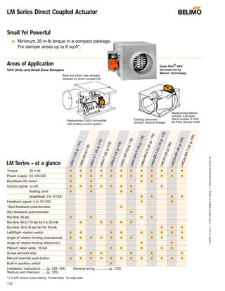
  • 1. 112 F20358/54321-01/04-10M-IG-Subjecttochange.©BelimoAircontrols(USA),Inc. LM Series Direct Coupled Actuator Areas of Application Small Yet Powerful q Minimum 35 in-lb torque in a compact package. For damper areas up to 8 sq-ft*. ® Torque: 35 in-lb q q q q q q q q q q q q Power supply : 24 VAC/DC q q q q q q q q q q q q Brushless DC motor: q q q q Control signal: on-off q q q q q q q q floating point q q q q proportional 2 to 10 VDC q q q q Feedback signal: 2 to 10 VDC q q 10kΩ feedback potentiometer q 5kΩ feedback potentiometer q Run time, 95 sec q q q q Run time, 80 to 110 sec for 0 to 35 in-lb q q q q q Run time, 25 to 35 sec for 0 to 18 in-lb q q q Left/Right rotation switch q q q q q q q q q Angle of rotation limiting (mechanical) q q q q q q q q q q Angle of rotation limiting (electronic) q q Plenum rated cable, 18 GA q q q q q q q Screw terminal strip q q q q q Manual override push-button q q q q q q q q q q q q Built-in auxiliary switch q Installation instructions ......(p. 122–124) General wiring ..............(p. 123) Start-up and checkout ......(p. 125) * 4 in-lb/ft2 damper torque loading. Parallel blade. No edge seals. LM Series – at a glance LM24-3US(p.114) LM24-3-TUS(p.114)LM24-TUS(p.118)LM24-SUS(p.118) LM24US(p.118) LM24-10PUS(p.118)LM24-5P0-TUS(p.118)LM24-SR-2.0US(p.116) LM24-SR-T-2.0US(p.116) LMC24US(p.120)LMC24-SRUS(p.120)LMC24-SR-TUS(p.120) Rack and pinion type actuator replaced by direct coupled LM. Replacement LM24 compatible with existing control system. Replacement Belimo actuator (LM type) direct couples to VAV By-Pass damper shaft. Existing pneumatic actuator requires linkage. VAV Units and Small Zone Dampers Quiet Plus ® VAV terminal unit by Warren Technology
  • 2. 113 F20358/54321-01/04-10M-IG-Subjecttochange.©BelimoAircontrols(USA),Inc. LM LISTED 94D5 TEMP. IND & REG. EQUIP. UL q Brushless DC Motor for added accuracy and controllability. q Cut labor costs with simple direct coupling. q Check damper position from a distance with clear position indication. q Don’t worry about actuator burn-out. Belimo is overload-proof throughout rotation. q Enjoy added flexibility with easy mechanical stops to adjust angle of rotation. (LM24-SR-2.0 US has electronic rotation limiting.) q Consistent running time independent of load. q Easily accessible manual override push-button helps you pre-tension damper blades. q Need to change control direction? Do it easily with a simple switch. q 3 ft. plenum rated cable eases installation (external terminal strip also available) Bulk Packaging Offers Big Value for Large Jobs, Stocking Orders. LM Series Direct Coupled Actuator ® The Belimo Difference q Customer Commitment. Extensive product range. Competitive project pricing. Application assistance. Same-day shipments. Free technical support. Five year warranty. q Low Installation and Life-Cycle Cost. Easy installation. Accuracy and repeatability. Low power consumption. No maintenance. q Long Service Life. Components tested before assembly. Every product tested before shipment. 20+ years direct coupled actuator design. A CLOSER LOOK… ©
  • 3. 114 F20358/54321-01/04-10M-IG-Subjecttochange.©BelimoAircontrols(USA),Inc. Application For on-off and floating point control of dampers in HVAC sys- tems. Actuator sizing should be done in accordance with the damper manufacturer’s specifications. The actuator mounts directly to the damper operating shaft with a universal V-bolt clamp assembly. Operation The actuator is not provided with and does not require any limit switches, but is electronically protected against overload. The angle of rotation is mechanically limited to 95°. When reaching the damper or actuator end position, the actuator automatically stops. The gears can be manually disengaged with a button on the actuator cover. The position of the actuator is indicated by a visual pointer. The anti-rotation strap supplied with the actua- tor will prevent lateral movement. The LM24-3 US and LM24-3-T US actuators use a Brushless DC motor, which is controlled by an Application Specific Integrated Circuit (ASIC). The ASIC monitors and controls the actuator’s rotation and provides a digital rotation sensing (DRS) function to prevent damage to the actuator in a stall condition. Accessories 11533 T-type anti-rotation bracket 22065 L-type anti-rotation bracket (included) ZG-LMSA Shaft adaptor for short shafts Tool-02 8 mm wrench LM24-3 (-T) US On-off/ floating point control, non-spring return, direct coupled, 24 V Dimensions (All numbers in brackets are metric.) Torque min. 35 in-lb, for control of damper surfaces up to 8 sq ft. LM24-3 US LM24-3-T US LM24-3 US LM24-3-T US LISTED 94D5 TEMP. IND & REG. EQUIP. UL ® Technical Data LM24… on-off/floating point Power supply 24 VAC ± 20% 50/60 Hz 24 VDC ± 10% Power consumption 2 W Transformer sizing 3 VA (Class 2 power source) Electrical connection* 3 ft, 18 GA, UL CL2P plenum cable Control On-off/Floating point Overload protection Electronic throughout 0 to 95° rotation Input impedance 3900Ω Angle of rotation max 95°, adjust. with mechanical stops Torque min 35 in-lb [4 Nm], Independent of load Direction of rotation reversible w/switch CW/CCW (not on “-T” models) Position indication clip-on indicator (not on “-T” models) Running time 95 seconds Manual override external push button Humidity 5 to 95% RH, non-condensing Ambient temperature -22°F to +122°F [-30°C to +50°C] Storage temperature -40°F to +176°F [-40°C to +80°C] Housing type NEMA type 2 (-T models NEMA 1) Housing material rating UL94-5V Noise level less than 35 dB (A) Servicing maintenance free Agency listings UL873 listed, CSA 22.2 No. 24 certified, CE Quality standard ISO 9001 Weight 1.2 lbs [0.55 kg] LM24-3-T.1 US Electrical connection Screw terminal (for 26 to 14 GA wire) Housing NEMA type 1 Direction of rotation Reverse wires terminals 2 and 3 *Standard cable length is 3 ft [1m]. Optional cable lengths of 6 ft [200m] or 10 ft [300m] are available at additional list price. © L R 20%100% 1 1 0 0 3.47" [88] 4.53" [115] 3.68" [93.5] 0.85" [21.5] 1.28" [32.5] 2.56" [65] 2.32" [58.9] 1/4" to 5/8" [6 to 16] 1/4" to 7/16" [6 to 11] D014
  • 4. 115 F20358/54321-01/04-10M-IG-Subjecttochange.©BelimoAircontrols(USA),Inc. LM 1 3224 VAC Transformer a open a closed The indication of direction is valid for switch position R. Blk (1) Common Red (2) + Wht (3) + LM24-3 (-T) US L R a Line Volts 1 2 324 VAC Transformer The indication of direction is valid for switch position CW. Blk (1) Common Red (2) + Wht (3) + LM24-3 US CCW CW Line Volts LM24-3 (-T) US On-off/ floating point control, non-spring return, direct coupled, 24 V LM24… on-off/floating - Typical Specification: Control damper actuators shall be electronic direct coupled type which require no crank arm and linkage. Actuators shall be UL and CSA listed, have a 5 year warranty, and be man- ufactured under ISO 9001 International Quality Control Standards. Actuators shall have Brushless DC motor tech- nology. Actuators shall have reversing switch and manual override on the cover, and be protected from overload at all angles of rotation. If required, actuator will be provided with screw terminal strip for electrical connections (LM24-3-T US). Actuators shall be as manufactured by Belimo. On-off control Line Volts 1 Common 2 + 3 + 24 VAC Transformer LM24-3-T US 6 51 2 Floating point or on-off control of LM24-3-T US 3 2 5 6 1 Provide overload protection and disconnect as required. Actuators may also be powered by 24 VDC. Actuators are provided with color coded wires. Wire numbers are provided for reference. The LM24-3-T US actuators are provided with a num- bered screw terminal strip instead of cable. Switch wires 2 and 3 to change rotation direction of LM24-3-T US (does not have CW/CCW external switch). Floating point or on-off control Bulk packaging Bulk Pack No. Actuator Type Quantity/Pack LM24-3.1 US LM24-3 US 32 LM24-3-T.1 US LM24-3-T US 48 ® Notes T-Type bracket These are included in the single-actuator packages and are available at no extra cost in the bulk packages upon request. Part # 11533 (UOM:1) L-Type anti-rotation bracket. Included with each bulk packaged actuator. W080 W082 W081 To have better control of job site inventory and reduce the environmental impact of unnecessary packing material. Part #: 22065 (UOM:1) 12502-00002 (includes 22065: UOM:16) shipped with bulk pack option.
  • 5. 116 F20358/54321-01/04-10M-IG-Subjecttochange.©BelimoAircontrols(USA),Inc. LM24-SR (-T) -2.0 US Proportional control, non-spring return, direct coupled, 24 V, for 2 to 10 VDC and 4 to 20 mA control signal Application For proportional modulation of dampers in HVAC systems. Actuator sizing should be done in accordance with the damper manufacturer’s specifications. The actuator mounts directly to the damper operating shaft with a universal V-bolt clamp assembly. The actuator operates in response to a 2 to 10 VDC or, with the addition of a 500 Ω resistor, a 4 to 20 mA input sig- nal from an electronic controller or positioner. A 2 to 10 VDC feedback signal is provided for position indication or master slave applications. (Not available on “-T” versions) The LM24-SR-2.0 US provides an electronic angle of rotation adjustment to limit the actuators rotation 20% to 100% while still using the full input signal and feedback control range. (Not available on LM24-SR-T-2.0 US) Operation The anti-rotation strap supplied with the actuator will prevent lat- eral movement of the actuator. The damper actuator is not pro- vided with and does not require any limit switches, but is pro- tected electronically against overload. The angle of rotation is mechanically limited to 95°. When reaching the damper or actu- ator end position, the actuator automatically stops. The gears can be manually disengaged by pressing a button on the actua- tor cover. The position of the actuator is indicated by a visual pointer. The LM24-SR-2.0 US and LM24-SR-T-2.0 US actuators use a Brushless DC motor, which is controlled by an Application Specific Integrated Circuit (ASIC). The ASIC monitors and controls the actuator’s rotation and provides a digital rotation sensing (DRS) function to prevent damage to the actuator in a stall condition. Accessories 11533 T-type anti-rotation bracket 22065 L-type anti-rotation bracket (included) ZG-LMSA Shaft adaptor for short shafts Tool-02 8 mm wrench ZG-R01 500Ω resistor for 4 to 20 mA Dimensions (All numbers in brackets are metric.) Torque min. 35 in-lb, for control of damper surfaces up to 8 sq ft. LM24-SR-2.0 US LM24-SR-T-2.0 US ® LM24-SR-T-2.0 USLM24-SR-2.0 US LISTED 94D5 TEMP. IND & REG. EQUIP. UL © Technical Data LM24-SR-2.0 US Power supply 24 VAC ± 20% 50/60 Hz 24 VDC ± 10% Power consumption 2 W Transformer sizing 4 VA (Class 2 power source) Electrical connection* LM24-SR-2.0 US: 3 ft, 18 GA, UL CL2P plenum cable Overload protection Electronic throughout 0 to 95° rotation Operating range Y 2 to 10 VDC, 4 to 20 mA Input impedance 100 kΩ (0.1 mA), 500Ω Feedback output ‘U’ 2 to 10 VDC (max. 0.7 mA ) (not available on LM24-SR-T-2.0 US Angle of rotation max 95°, electronically adjustable 20 to 100% on LM24-SR-2.0 US Torque min 35 in-lb, Independent of load Direction of rotation reversible with switch CW/CCW CW = with an increase in voltage CCW = with an increase in voltage Position indication clip-on indicator (not on “-T” models) Running time 95 seconds Manual override external push button Humidity 5 to 95% RH, non-condensing Ambient temperature -22°F to +122°F [-30°C to +50°C] Storage temperature -40°F to +176°F [-40°C to +80°C] Housing type NEMA type 2 (-T models Nema type1) Housing material rating UL 94-5V Noise level less than 35 dB (A) Servicing maintenance free Agency listings UL 873 listed, CSA 22..2 No. 24 certified, CE Quality standard ISO 9001 Weight 1.2 lbs [0.55 kg] LM24-SR-T-2.0.1 US Electrical connection Screw terminals (for 26 to 14 GA wire) Angle of rotation max 95°, adjust. with mechanical stops Housing NEMA type 1 Feedback No feedback with the LM24-SR-T-2.0 US *Standard cable length is 3 ft [1m]. Optional cable lengths of 6 ft [200m] or 10 ft [300m] are available at additional list price. L R 20%100% 1 1 0 0 3.47" [88] 4.53" [115] 3.68" [93.5] 0.85" [21.5] 1.28" [32.5] 2.56" [65] 2.32" [58.9] 1/4" to 5/8" [6 to 16] 1/4" to 7/16" [6 to 11] D014
  • 6. 117 F20358/54321-01/04-10M-IG-Subjecttochange.©BelimoAircontrols(USA),Inc. LM LM24-SR (-T) -2.0 US Proportional control, non-spring return, direct coupled, 24 V, for 2 to 10 VDC and 4 to 20 mA control signal 1 2724 VAC Transformer Blk (1) Common Red (2) + Hot Wht (3) Y 2 to 10V Input Grn (5) U 2 to 10V Output LM24-SR-2.0 US CCW CW Line Volts 2 to 10 VDC Control Signal 2 to 10 VDC Feedback Signal (–) (+) (–) (+) 6 1 2724 VAC Transformer Blk (1) Common Red (2) + Hot Wht (3) Y 2 to 10V Input Grn (5) U 2 to 10V Output LM24-SR-2.0 US CCW CW Line Volts 4 to 20 mA Control Signal 2 to 10 VDC Feedback Signal (–) (+) (–) (+) 6 8 Ω 500Ω 2 to 10 VDC control of LM24-SR-2.0 US 4 to 20 mA control of LM24-SR-2.0 US with 2 to 10 VDC feedback output 2 4 5 6 7 8 1 Provide overload protection and disconnect as required. Actuators are provided with color coded wires. Wire numbers are provided for reference. The LM24-SR-T-2.0 US is provided a screw terminal instead of cable. The LM24-SR-T-2.0 US does not have feedback. Connect actuator common (Wire 1) to Negative (–) leg of control circuits only. Actuators may also be powered by 24 VDC. A 500Ω resistor (ZG-R01) must be added for 4 to 20 mA control. 1 4724 VAC Transformer 1 Common 2 + Hot 3 Y 2 to 10V Input LM24-SR-T-2.0 US CCW CW Line Volts 4 to 20 mA Control Signal w/500Ω resistor (–) (+) 6 8 Ω 500Ω 2 to 10 VDC 5 2 to 10 VDC and 4 to 20 mA control of LM24-SR-T-2.0 US ® Bulk packaging LM24SR-2.0 US and LM24SR-T-2.0 US LM24-SR (-T) 2.0 US - Typical Specification: Control damper actuators shall be electronic direct coupled type which require no crank arm and linkage. Actuators shall be UL and CSA listed, have a 5 year warranty, and be man- ufactured under ISO 9001 International Quality Control Standards. Actuators shall have Brushless DC motor. Actuators shall have reversing switch and gear disengage- ment button on the cover, and be electronically protected from overload at all angles of rotation. Actuators shall respond to 2 to 10VDC output relative to position regardless of the amount of damper rotation. A 2 to 10 VDC feedback signal shall be provided for position indication or master-slave applications. Actuators shall be as manufactured by Belimo. An electronic angle of rotation adjustment shall be provided to reduce the actuators rotation from 100 to 20% while still using the full input signal and feedback control range. (LM24-SR US) If required, actuator will be provided with screw terminal strip for electrical connections (LM24-SR-T US). Notes Bulk Pack No. Actuator Type Quantity/Pack LM24-SR-2.0.1 US LM24-SR-2.0 US 32 LM24-SR-T.-2.0.1 US LM24-SR-T-2.0 US 48 T-Type bracket These are included in the single-actuator packages and are available at no extra cost in the bulk packages upon request. Part # 11533 (UOM:1) W083W084 W085 To have better control of job site inventory and reduce the environmental impact of unnecessary packing material. L-Type anti-rotation bracket. Included with each bulk packaged actuator. Part #: 22065 (UOM:1) 12502-00002 (includes 22065: UOM:16) shipped with bulk pack option.
  • 7. 118 F20358/54321-01/04-10M-IG-Subjecttochange.©BelimoAircontrols(USA),Inc. Application For on-off control of dampers in HVAC systems. Actuator siz- ing should be done in accordance with the damper manufac- turer’s specifications. The actuator mounts directly to the damper operating shaft with a universal V-bolt clamp assem- bly. Operation The actuator is not provided with and does not require any limit switches, but is electronically protected against overload. The angle of rotation is mechanically limited to 95°. When reaching the damper or actuator end position, the actuator automatically stops. The gears can be manually disengaged with a button on the actuator cover. The position of the actua- tor is indicated by a visual pointer. The anti-rotation strap sup- plied with the actuator will prevent lateral movement. Accessories LM-P T-type anti-rotation bracket ZG-LMSA Shaft adaptor for short shafts Tool-02 8 mm wrench LM24 (-T) US On-off control, non-spring return, direct coupled, 24 V Torque min. 35 in-lb, for control of damper surfaces up to 8 sq ft. LM24 US LM24-S US LM24-10P US LM24-5P0-T US LM24-T US LM24-S US LM24-T US LISTED 94D5 TEMP. IND & REG. EQUIP. UL Technical Data LM24… on-off/floating point Power supply 24 VAC ± 20% 50/60 Hz 24 VDC ± 10% Power consumption 2 W Transformer sizing 3 VA (Class 2 power source) Electrical connection* 3 ft, 18 GA, UL CL2P plenum cable Control On-off Overload protection Electronic throughout 0 to 95° rotation Angle of rotation max 95°, adjust. with mechanical stops Torque min 35 in-lb [4 Nm] Direction of rotation reversible w/switch L/R (not on “-T” models) Position indication clip-on indicator (not on “-T” models) Running time 80 to 110 sec. for 0 to 35 in-lb Manual override external push button Humidity 5 to 95% RH, non-condensing Ambient temperature -22°F to +122°F [-30°C to +50°C] Storage temperature -40°F to +176°F [-40°C to +80°C] Housing type NEMA type 2 (-T models NEMA 1) Housing material rating UL94-5V Noise level less than 35 dB (A) Servicing maintenance free Agency listings UL 873 listed, CSA C22.2 No.24 certified, CE Quality standard ISO 9001 Weight 1.2 lbs [0.55 kg] LM24-S US Control On-off Auxiliary switch Adj. 0° to 95°, SPDT 6 A (2.5A) @ 24 VAC LM24-10P US Control On-off/Floating point Feedback 10 kΩ, 1W potentiometer LM24-5P0-T.1 US (bulk pack only) Control On-off/Floating point Feedback 5 kΩ, 1W potentiometer Housing NEMA type 1 Direction of rotation Reverse wires terminals 2 and 3 LM24-T.1 US (bulk pack only) Control On-off Electrical connection Screw terminal (for 26 to 14 GA wire) Housing NEMA type 1 Direction of rotation Reverse wires terminals 2 and 3 *Standard cable length is 3 ft [1m]. Optional cable lengths of 6 ft [200m] or 10 ft [300m] are available at additional list price. ® Dimensions (All numbers in brackets are metric.) 1 1 0 0 3.47" [88] 4.53" [115] 3.68" [93.5] 0.85" [21.5] 1.28" [32.5] 2.56" [65] 2.32" [58.9] 1/4" to 5/8" [6 to 16] 1/4" to 7/16" [6 to 11] D015
  • 8. 119 F20358/54321-01/04-10M-IG-Subjecttochange.©BelimoAircontrols(USA),Inc. LM 1 5 3224 VAC Transformer a open a closed The indication of direction is valid for switch position R. Blk (1) Common Red (2) + Wht (3) + LM24 -T US LM24 (-S) US LM24-10P US L R a Line Volts 1 2 3 4 24 VAC Transformer The indication of direction is valid for switch position R. Blk (1) Common Red (2) + Wht (3) + LM24-10P US L R Line Volts LM24-S US S1 S2 S3 NC NO 0° to 95° LM24 (-T) US On-off control, non-spring return, direct coupled, 24 V LM24… on-off - Typical Specification: Control damper actuators shall be electronic direct coupled type which require no crank arm and linkage. Actuators shall be UL and CSA listed, have a 5 year warranty, and be man-ufactured under ISO 9001 International Quality Control Standards. Actuators shall have reversing switch and manual override on the cover, and be protected from overload at all angles of rota- tion. If required, actuator will be provided with screw terminal strip for electrical connections (LM24-T US and LM24-5P0-T US). If required, one adjustable SPDT auxiliary switch shall be provided (LM24-S US). If required, actuators shall be provided with a built- in 10 kΩ feedback potentiometer (LM24-10P US) or 5kΩ (LM24- 5P0-T) for use in modulating (floating point) applications. Actuators shall be as manufactured by Belimo. On-off control Line Volts 1 Common 2 + 3 + 24 VAC Transformer LM24-5P0-T US 6 4 51 2 3 LM24-10P US LM24-5P0-T US 0 10/5 10kΩ/5kΩ Feedback potentiometer 7 5 4 7 Org (P1) Blue (P2) Yel (P3) Floating point or on-off control Feedback potentiometer wiring for LM24-10P US and LM24-5P0-T US Auxiliary switch wiring for LM24-S US 3 2 4 5 6 7 1 Provide overload protection and disconnect as required. Actuators may also be powered by 24 VDC. Actuators are provided with color coded wires. Wire numbers are provided for reference. For position indication, the LM24-10P US is provided with a 10 kΩ feedback potentiometer and the LM24-5P0-T US is provided with a 5 kΩ feedback potentiometer. The LM24-T US and LM24-5P0-T US are provided with a numbered screw terminal strip instead of cable. Switch wires 2 and 3 to change rotation direction of LM24-T US and LM24-5P0-T US (does not have L/R external switch). Value based on resistance between (P1) and (P2). indicates direction of rotation of actuator. Floating point or on-off control Bulk packaging LM24 on-off/floating Bulk Pack No. Actuator Type Quantity/Pack LM24.1 US LM24 US 32 LM24-T.1 US LM24-T US 48 LM24-5P0-T.1 US LM24-5P0-T US 48 L-Type anti-rotation bracket. Included with each actuator. Part #: 22065 Notes ® W086 W089 W087W088 W090
  • 9. 120 F20358/54321-01/04-10M-IG-Subjecttochange.©BelimoAircontrols(USA),Inc. Application For on-off control of dampers in HVAC systems (LMC24 US). For proportional modulation of dampers in HVAC systems (LMC24-SR-T US). Actuator sizing should be done in accor- dance with the damper manufacturer’s specifications. The actuator mounts directly to the damper operating shaft with a universal V-bolt clamp assembly. The LMC24-SR-T US actuator operates in response to a 2 to 10 VDC or, with the addition of a 500 Ω resistor, a 4 to 20 mA input signal from an electronic controller or positioner. A 2 to 10 VDC feedback signal is provided for position indication or master slave applications. The LMC24-SR US provides an electronic angle of rotation adjustment (not available in the LMC24-SR-T US) to limit the actuators rotation 20% to 100% while still using the full input signal and feedback control range. Operation The actuator is not provided with and does not require any limit switches, but is electronically protected against overload. The angle of rotation is mechanically limited to 95°. When reaching the damper or actuator end position, the actuator automatically stops. The gears can be manually disengaged with a button on the actuator cover. The position of the actuator is indicated by a visual pointer. The anti-rotation strap supplied with the actuator will prevent lateral movement. Accessories LM-P T-type anti-rotation bracket IRM-100 Input scaling module (For LMC24-SR-T US only) ZG-LMSA Shaft adaptor for short shafts PTA-250 Pulse width modulating interface (For LMC24-SR-T US only) SGA24 Min. and/or manual positioner in NEMA 4 housing (For LMC24-SR-T US only) SGF24 Min. and/or manual positioner for flush panel mount (For LMC24-SR-T US only) Tool-02 8 mm wrench ZAD24 Digital position indication (For LMC24-SR-T US only) ZG-R01 500Ω resistor for 4 to 20 mA (For LMC24-SR-T US only) LMC24 (-SR) (-T) US Non-spring return, direct coupled, 24 V, 25 to 35 sec. running time Torque min. 18 in-lb, for control of damper surfaces up to 4.5 sq ft. LMC24 US (on/off) LMC24-SR US (proportional) LMC24-SR-T US (proportional) LMC24 US LMC24-SR US LISTED 94D5 TEMP. IND & REG. EQUIP. UL ® Technical Data LMC24 (-SR) US… Power supply 24 VAC ± 20% 50/60 Hz 24 VDC ± 10% Power consumption LMC24 US 2.0 W LMC24-SR (-T) US 2.5 W Transformer sizing LMC24 US 3 VA LMC24-SR (-T) US 4 VA Electrical connection 3 ft, 18 GA, UL CL2P plenum cable Control On-off (LMC24 US) Overload protection Electronic throughout 0 to 95° rotation Angle of rotation max 95°, adjust. with mechanical stops (LMC24 US), electronically adjustable 20 to 100% on LMC24-SR US only Torque min 18 in-lb [2 Nm] Operating range Y 2 to 10 VDC, 4 to 20 mA (LMC24-SR (-T) US) Input impedance 100 kΩ (0.1 mA), 500Ω (LMC24-SR (-T) US) Feedback output ‘U’ 2 to 10 VDC (max. 0.7 mA ) (LMC24-SR-T US) Direction of rotation reversible with switch “CCW-CW” LMC24-SR-T US: CW with a decrease in voltage CCW with a decrease in voltage Position indication clip-on indicator Running time 25 to 35 sec. for 0 to 18 in-lb Manual override external push button Humidity 5 to 95% RH, non-condensing Ambient temperature -22°F to +122°F [-30°C to +50°C] Storage temperature -40°F to +176°F [-40°C to +80°C] Housing type NEMA type 2 Housing material rating UL94-5V Noise level less than 35 dB (A) Servicing maintenance free Agency listings UL 873 listed, CSA C22.2 No.24 certified, CE Quality standard ISO 9001 Weight 1.2 lbs [0.55 kg] LMC24-SR-T US Electrical connection Screw terminals (for 26 to 14 GA wire) Angle of rotation max 95°, adjust. with mechanical stops Housing NEMA type 1 Feedback No feedback with the LMC24-SR-T US Note: Actuators do not have Brushless DC Motor Dimensions (All numbers in brackets are metric.) 1 1 0 0 3.47" [88] 4.53" [115] 3.68" [93.5] 0.85" [21.5] 1.28" [32.5] 2.56" [65] 2.32" [58.9] 1/4" to 5/8" [6 to 16] 1/4" to 7/16" [6 to 11] D015
  • 10. 121 F20358/54321-01/04-10M-IG-Subjecttochange.©BelimoAircontrols(USA),Inc. LM 1 3224 VAC Transformer a open a closed The indication of direction is valid for switch position CW. Blk (1) Common Red (2) + Wht (3) + LMC24 US CCW CW a Line Volts LMC24 (-SR) (-T) US Non-spring return, direct coupled, 24 V, 25 to 35 sec. running time LMC24… - Typical Specification: Control damper actuators shall be electronic direct coupled type which require no crank arm and linkage. Actuators shall be UL and CSA listed, have a 5 year warranty, and be man- ufactured under ISO 9001 International Quality Control Standards. Actuators shall have reversing switch and manual override on the cover, and be protected from overload at all angles of rotation. Actuator shall have a nominal running time of 30 seconds for 95° rotation. Proportional actuators shall respond to 2 to 10VDC output relative to position regardless of the amount of damper rotation. A 2 to 10 VDC feedback sig- nal shall be provided for position indication or master-slave applications. An electronic angle of rotation adjustment (LMC24-SR US only) shall be provided to reduce the actuators rotation from 100 to 20% while still using the full input signal and feedback control range. Actuators shall be as manufac- tured by Belimo. On-off control 3 2 4 5 6 1 Provide overload protection and disconnect as required. Actuators may also be powered by 24 VDC Actuators are provided with color coded wires. Wire numbers are provided for reference. Connect actuator common (Wire 1) to Negative (–) leg of control circuits only. A 500Ω resistor (ZG-R01) must be added for 4 to 20 mA control. LMC24-SR-T US does not have a cable. Numbers shown are terminal numbers. L-Type anti-rotation bracket. Included with each actuator. Part #: 22065 ® Notes 1 3224 VAC Transformer Blk (1) Common Red (2) + Hot Wht (3) Y 2 to 10V Input Grn (5) U 2 to 10V Output LMC24-SR (-T) US CCW CW Line Volts 2 to 10 VDC Control Signal 2 to 10 VDC Feedback Signal (–) (+) (–) (+) 4 6 1 3224 VAC Transformer Blk (1) Common Red (2) + Hot Wht (3) Y 2 to 10V Input Grn (5) U 2 to 10V Output LMC24-SR (-T) US CCW CW Line Volts 4 to 20 mA Control Signal 2 to 10 VDC Feedback Signal (–) (+) (–) (+) 4 65 Ω 500Ω 2 to 10 VDC control of LMC24-SR (-T) US 4 to 20 mA control of LMC24-SR (-T) US with 2 to 10 VDC feedback output W151 W153W154
  • 11. 122 F20358/54321-01/04-10M-IG-Subjecttochange.©BelimoAircontrols(USA),Inc. Preliminary steps 1. Belimo actuators should be mounted indoors in dry, relatively clean environment free from corrosive fumes. If the actuator is to be mounted outdoors, a protective enclosure must be used to shield the actuator. (See Belimo Mechanical Accessories Doc. 5.2) 2. For new construction work, order dampers with extended shafts. Instruct the installing contractor to allow space for mounting and service of the Belimo actuator on the shaft. 3. The LM Series actuator requires a minimum shaft length of 1.5”. Use the ZG-LMSA for short shaft installations on 1/2” diameter shafts. Installation Instructions Quick-mount visual instructions ® 1. Turn damper blade to its fully closed position. 2. With manual override button depressed, rotate actuator clamp to about 1/16” - 1/8” between actuator stop and clamp, depending on damper seal design. Slide actuator over shaft and finger-tighten nuts. 3. Slide anti-rotation bracket up under actuator engaging cen- ter cut-out on actuator back. Secure bracket with self-tap- ping screws. Tighten the two nuts on the universal clamp with 8 mm wrench, 3-5 ft-lb torque. (On dampers with edge seals, actuator will compress damper blades when reaching end posi- tion for air-tight damper.) 4. Adjust end stops, if required. 1 2 3 4 L-bracket L-bracket min. 1.5” [38] Dimensions (All numbers in brackets are metric.)
  • 12. WARNING The wiring technician must be trained and experi- enced with electronic circuits. Disconnect power supply before attempting any wiring connections or changes. Make all con- nections in accordance with wiring diagrams and follow all applicable local and national codes. Provide disconnect and overload protection as required. Use copper, twisted pair, conductors only. Always read the controller manufacturer's installation liter- ature carefully before making any connections. Follow all instructions in this literature. If you have any questions, contact the controller manufacturer and/or Belimo. Transformer(s) The LM Series actuators require a 24 VAC class 2 transformer and draw a maximum of 4 VA. The actuator enclosure cannot be opened in the field, there are no parts or components to be replaced or repaired. – EMC directive: 89/336/EEC – Software class A: Mode of operation type 1 – Low voltage directive: 73/23/EEC CAUTION: It is good practice to power electronic or digital con- trollers from a separate power transformer than that used for actuators or other end devices. The power supply design in our actuators and other end devices use half wave rectification. Some controllers use full wave rectification. When these two different types of power supplies are connected to the same power transformer and the DC commons are connected togeth- er, a short circuit is created across one of the diodes in the full wave power supply, damaging the controller. Only use a single power transformer to power the controller and actuator if you know the controller power supply uses half wave rectification. Multiple actuators, one transformer Multiple actuators may be powered from one transformer pro- vided the following rules are followed: 1. The TOTAL current draw of the actuators (VA rating) is less than or equal to the rating of the transformer. 2. Polarity on the secondary of the transformer is strictly fol- lowed. This means that all No. 1 wires from all actuators are connected to the common leg on the transformer and all No 2 wires from all actuators are connected to the hotleg. Mixing wire No. 1 & 2 on one leg of the transformer will result in erratic operation or failure of the actuator and or controls. Multiple actuators, multiple transformers Multiple actuators positioned by the same control signal may be powered from multiple transformers provided the following rules are followed: 1. The transformers are properly sized. 2. All No. 1 wires from all actuators are tied together and tied to the negative leg of the control signal. See wiring diagram. Wire length for LM Series actuators Keep power wire runs below the limits listed in the Fig. 1. If more than one actuator is powered from the same wire run, divide the allowable wire length by the number of actuators to determine the maximum run to any single actuator. Maximum wire length: Wire Size Max. Feet. Wire Size Max. Feet 16 Ga 1225 Ft. 20 Ga 400 Ft 18 Ga 725 Ft. 22 Ga 200 Ft Fig. 1 Example for LM… US: 3 actuators, 18 Ga wire 725 Ft ÷ 3 Actuators = 241.6 Ft. Maximum wire run. Wire Type and Wire Installation Tips For most installations, 18 or 16 Ga. cable works well with the LM24 type actuators. Use code approved wire nuts, terminal strips or solderless connectors where wires are joined. It is good practice to run control wires unspliced from the actuator to the controller. If splices are unavoidable, make sure the splice can be reached for possible maintenance. Tape and/or wire tie the splice to reduce the possibility of the splice being inadvertently pulled apart. LM Series Actuators with Terminal Strip LM…-T actuators feature an external screw terminal strip on the top of the actuator housing (instead of cable). Connections are numbered and a wiring schematic is shown next to the ter- minal strip. The terminals are designed for 26 to 14 GA wire. Overload protection All Belimo actuators are electronically protected against over- load. In the LM series an electronic circuit maintains the cur- rent at a level which will not damage the motor while providing adequate holding torque. Installation Instructions General Wiring 123 F20358/54321-01/04-10M-IG-Subjecttochange.©BelimoAircontrols(USA),Inc. LM ® 0 1 Manual Override A button on the actuator cover disengages the gear train so the damper shaft can be moved manually. Release the button and the gear train is re-engaged. Use the manual override to test the installation without power. For tight shut-off the damper should close with 5° of actuator stroke left. 0 1 Gear release button
  • 13. AF 124 F20358/54321-01/04-10M-IG-Subjecttochange.©BelimoAircontrols(USA),Inc. 0 1 Adjust angle-of-rotation in steps of 2.5° Installation Instructions Feature Operation Mechanical Angle of Rotation Limiting (LM Series, On-Off/Floating and LM24-SR-T-2.0 US) The adjustable stops are needed when there is no damper stop or if you want the damper to halt rotating before it reaches its stops. The LM actuator can be indefinitely stalled in any posi- tion without harm. 1. Loosen the two end stops with a No. 2 Phillips head screwdriv- er being careful not to unscrew the captive nut under the slot. 2. Move the stops (in 2.5° steps) to the desired position and re- tighten the screws. LM actuators have a reversing switch on the cover labeled “CW- CCW”. Switch position indicates start point. For the LM24-SR (-T) 2.0 US, with the switch in position “CW”, the actuator rotates clock- wise with an increase in voltage or current. With the switch in posi- tion “CCW”, the actuator rotates counterclockwise with an increase in voltage or current. The LM24-3-T US does not have a switch. They rotate clock- wise when power is applied to wire #3, and counterclockwise when power is applied to wire #2. During checkout, the switch position can be temporarily reversed and the actuator will reverse its direction. This allows the technician a fast and easy way to check the actuator opera- tion without having to switch wires or change settings on the thermostat. When the check-out is complete, make sure the switch is placed back to its original position. CW CCW 0 1 CW CCW 0 1 10 VDC2 VDC 2 VDC10 VDC Direction of rotation switch. Position indicates start point. Electronic Angle of Rotation Limiting (LM24-SR-2.0 US) With the LM24-SR-2.0 US proportional actuator, you can adjust the angle of rotation (95°) anywhere between 20% and 100% using an external adjustment. A potentiometer limits rotation while allowing the full control input and feedback range (2 to 10 VDC), providing higher control resolution within the lim- ited angle of rotation. CCW 0 1 CW CW CCW 2 VDC 10 VDC 45°/50% Limit Feedback signal will also be adjusted 2 to 10 VDC 0 1 2 VDC 10 VDC 45°/50% Limit 0 1 20% 100% 100%20% Limitationsetat50% Angleofrotation=45° Controlsignal=10VDC Direction of Rotation Switch (All LM except LM24-3-T US) ®
  • 14. 125 F20358/54321-01/04-10M-IG-Subjecttochange.©BelimoAircontrols(USA),Inc. LM ® Procedure Control signal is applied to actuator. Check power wiring. Correct any problems. See Note 1. Turn reversing switch to the correct position. Make sure the control signal positive (+) is connected to Wire No 3 and control signal negative (-) is connect- ed to wire No. 1. Most control prob- lems are caused by reversing these two wires. Verify that the reversing switch is all the way CCW or CW. Check input signal with a digital volt meter (DVM). Make sure the input is within the range of the actuator. For LM24SR (-T) US this is 0 to 10 VDC or 0 to 20 mA. Note: The input signal must be above the 2 VDC or 4 mA to have the actua- tor move. Use the manual override button to move the damper by hand from fully closed to fully open. Check damper torque requirement. Actuator works properly. Test con- troller by following controller manu- facturer's instructions. Expected Response Actuator will move to its “Control Signal” position. Power supply rating should be ≥ the total power requirement of the actuator(s). Minimum volt- age of 19.2 VAC or 21.6 VDC. Actuator will move to its “Control Signal” position. Drives to “Control Signal” posi- tion Input voltage or current should be ±1% of what controller's adjustment or programming indi- cate. Damper will go from fully closed to fully open. Torque requirement is ≤ actua- tor’s minimum torque. Gives Expected Response Go To Step… Actuator operates properly Step 8 Power wiring correct- ed, actuator begins to drive Step 1 Actuator operates properly. Step 8 Actuator operates properly. Step 8 Controller output (actuator input) is correct. Input Polarity Correct. Step 6 Damper moves properly Step 7 Defective Actuator. Replace Actuator - See Note 2 Does Not Give Expected Response Go To Step… No response at all Step 2 Operation is reversed Step 3 Does not drive toward "Control Signal Position" Step 4 Power wiring corrected, actuator still does not drive Step 4 Does not drive toward “Control Signal Position” Step 4 Step 5 Reprogram, adjust repair or replace controller as needed. Step 1 Find cause of damper jam and repair. Step 1 Recalculate actuator requirement and correct installation. Step 1. 2. 3. 4. 5. 6. 7. 8. Note 1 Check that the transformer(s) are sized properly. • If a common transformer is used, make sure that polarity is observed on the secondary. This means connect all No. 1 wires to one leg of the transformer and all No. 2 wires to the other leg of the transformer. • If multiple transformers are used with one control signal, make sure all No. 1 wires are tied together and tied to control signal negative (-). • Controllers and actuators must have separate 24 VAC/VDC power sources. Note 2 If failure occurs within 5 years from original installation date, notify Belimo and give details of the application. LM24-SR (-T) 2.0 US Electrical check-out procedure Startup and Checkout