1. Simple LED flasher circuits
By simple, I mean that these circuits only flash one or two LEDs. This is opposed to
the light chaser circuits that can flash four or more. Of course, the simplest LED flasher is
simply to use a flashing LED. The problem with that approach is you have no control
over the flash rate, but it does have its use for eye catching displays for selling stuff. The
circuits below give you that control, plus they can flash two LEDs alternately.
There are many possible applications for the circuits below, especially for kids, who love
flashing lights. Here's some possible uses.
Railroad crossing signal for model railroads.
Safety blinkers for bicycles, etc.
Fun stuff for Halloween, like making those plastic Jack-O-lanterns blink (try
using ultraviolet LEDs here).
Christmas decorations.
Blinkers to locate items in the dark.
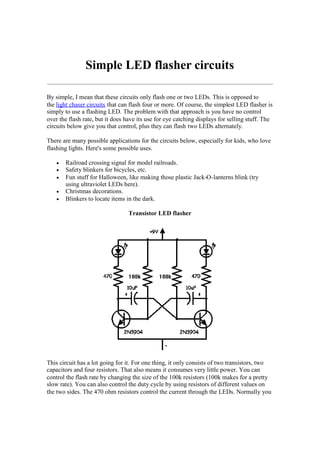
Transistor LED flasher
This circuit has a lot going for it. For one thing, it only consists of two transistors, two
capacitors and four resistors. That also means it consumes very little power. You can
control the flash rate by changing the size of the 100k resistors (100k makes for a pretty
slow rate). You can also control the duty cycle by using resistors of different values on
the two sides. The 470 ohm resistors control the current through the LEDs. Normally you
2. want to limit this to 20mA, but to conserve battery power, you may need to limit it even
further. You can also connect several LEDs in series, instead of using only one for each
side. With red LEDs (1 per side) and the values shown, the circuit draws about 11mA.
Here's what the actual circuit looks like:
On this circuit, the green wires connect to the LEDs, but you can mount them on the
actual circuit board for some applications. The picture is about twice actual size. Here is
an example of the use of this circuit:
Basic LED flasher circuit using NE555 timer IC
3. This circuit consumes more power, but it's advantage is when you need a variable flash
rate, like for strobe circuits. You can actually use this circuit as a remote control for
strobes that have a remote input. Of course, it has many other applications besides strobes.
R1, R2, C1 and the supply voltage determine the flash rate. Using a regulated
power supply will do much to insure a stable flash rate. For a variable flash rate,
replace R1 with a 1 megohm pot in series with a 22k resistor.
The duty cycle of the circuit (the percentage of the time LED 1 is on to the time it
is off during each cycle) is deterimed by the ratio of R1 to R2. If the value of R1
is low in relationship to R2, the duty cycle will be near 50 percent. If you use both
LEDs, you will probably want a 50 percent duty cycle. On the other hand, if R2 is
low compared to R1, the duty cycle will be less than 50 percent. This is useful to
conserve battery life, or to produce a strobe type effect, when only LED1 is used.
The NE555 timer chip can be damaged by reverse polarity voltage being applied
to it. You can make the circuit goof proof by placing a diode in series with one of
the supply leads.
The purpose of R3 and R4 is to limit current through the LEDs to the maximum
they can handle (usually 20 milliamps). You should select the value of these
according to the supply voltage. 470 ohms works well with a supply voltage of 912 volts. You will need to reduce the value for lower supply voltages.
Rainbow Kits offers several kits to build the above circuit. You can also order
these kits from RadioShack.com. The Radio Shack catalog numbers (and web
pages) are as follows: standard kit with two 5mm red LEDs, (990-0067), kit with
two red, two green and two yellow 3mm LEDs, (990-0063), kit with jumbo green
LEDs, (990-0048), kit with jumbo red LEDs, (990-0049). You can also buy all
the parts to build the circuit at your local Radio Shack store, including a circuit
board (276-159B).