
Recomendados
Mais conteúdo relacionado
Mais procurados
Mais procurados (20)
Destaque
Destaque (7)
Semelhante a Lesson 05,bending and shearing stresses
Semelhante a Lesson 05,bending and shearing stresses (20)
Mais de Msheer Bargaray
Último
Último (20)
Lesson 05,bending and shearing stresses
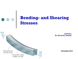
- 1. Bending- and Shearing Stresses Lecturer; Dr. Dawood S. Atrushi December 2014
- 2. Chapter 5 Stresses in Beam (Basic Topics) Deflection Curve ¢ Lateral loads acting on a beam cause the beam to bend, thereby deforming the axis of the beam into curve line, this is known as the deflection curve of the beam. 2 Bending Stresses - DAT December, 2014 Introduction loads acting transversely to the longitudinal axis loads create shear forces and bending moments, stresses and strains due to V are discussed in this chapter lateral loads acting on a beam cause the bend, thereby deforming the axis of beam into curve line, this is known as deflection curve of the beam beams are assumed to be symmetric about x-y plane, i.e. y-axis axis of symmetric of the cross section, all loads are assumed to act in
- 3. Plane of bending The beams are assumed to be symmetric about x-y plane, i.e. y-axis is an axis of symmetric of the cross section, all loads are assumed to act in the x-y plane, then the bending deflection occurs in the same plane, it is known as the plane of bending. Deflection of beam It is the displacement of that point from its original position, measured in y direction. 3 Bending Stresses - DAT December, 2014
- 4. known as the plane of bending the deflection Pure of the Bending beam is the displacement and of Non-uniform that point from its original position, measured in y direction Bending 5.2 Pure Bending and Nonuniform Bending Pure bending: M = constant V = dM / dx = 0 pure bending : M = constant V = dM / dx = 0 pure bending in simple beam and cantilever beam are shown 1 4 Bending Stresses - DAT December, 2014
- 5. Non-uniform bending: M ≠ constant V = dM / dx ≠ 0 nonuniform bending : M J constant Simple beam with V = dM central / dx J region 0 in pure bending and simple beam with central region in pure end regions in non-uniform bending and end regions bending. in nonuniform bending is shown 5.3 Curvature of a Beam 5 Bending Stresses - DAT December, 2014 consider a cantilever beam subjected to a
- 6. simple beam with central region in pure bending and end regions in nonuniform bending is shown 5.3 Curvature of a Beam Curvature of a Beam Consider a cantilever beam subjected to a load P. Choose 2 points m1 and m2 on the deflection curve, consider a cantilever beam subjected to a load P choose 2 points m1 and m2 on the 5.3 Curvature of a Beam consider a cantilever beam subjected to a load P choose 2 points m1 and m2 on the deflection curve, their normals intersect at point O', is called the center of curvature, the distance m1O' is called radius of curvature !, and the curvature is defined as deflection curve, their normals intersect at point O', is called the center of curvature, the distance m1O' is called radius of curvature !, and the curvature is defined as l Center of curvature; intersection of their normals at point O’. l radius of curvature ρ; the distance m1O’ l Curvature κ is defined as = 1 /! = 1 /! 6 Bending Stresses - DAT December, 2014 and we have ! d = ds and we have d= ds
- 7. deflection curve, their normals intersect at point O', is called the center of curvature, the distance m1O' is called radius of curvature !, and the curvature is defined as Curvature of a Beam consider a cantilever beam subjected to a We have; ρdθ = ds = 1 /! If the deflection is small ds ≈ dx, then and we have ! d = ds if the deflection is small ds M dx, then 1 d d = C = C = C 7 Bending Stresses - DAT December, 2014 P choose 2 points m1 and m2 on the deflection curve, their normals intersect at O', is called the center of curvature, distance m1O' is called radius of curvature !, and the curvature is as = 1 /! we have ! d = ds deflection is small ds M dx, then !ds dx sign convention for curvature
- 8. deflection curve, their normals intersect at point O', is called the center of curvature, the distance m1O' is called radius of curvature !, and the curvature is We have; ρdθ = ds defined as = 1 /! If the deflection is small ds ≈ dx, then and we have ! d = ds if the deflection is small ds M dx, then 1 d d = C = C = C !ds dx 8 Bending Stresses - DAT December, 2014 sign convention for curvature 1 /! ! d = ds deflection is small ds M dx, then 1 d d C = C = C !ds dx convention for curvature bent concave upward (convex downward) bent concave downward (convex upward)
- 9. Longitudinal Strains in Beams Consider a portion AB of a beam in pure bending produced by a positive bending moment M, the cross section may be of any shape provided it is symmetric about y-axis; 5.4 Longitudinal Strains in Beams consider a portion ab of a beam in pure bending produced by a positive bending moment M, the cross section may be of any shape provided it is symmetric about y-axis 9 Bending Stresses - DAT December, 2014 under the moment M, its axis is bent into a circular curve, cross
- 10. cross section may be of any shape 10 Bending Stresses - DAT December, 2014
- 11. Under the moment M, its axis is bent into a circular curve, pure bending produced by a section may be of any shape into a circular curve, cross normal to longitudinal lines ¢ cross section mn and pq remain plane and normal to longitudinal lines ¢ the curve is circular ¢ longitudinal lines nq are elongated, and mp are shortened. ¢ the surface ss do not change in length and is called the neutral surface. ¢ its intersection with the cross-sectional plane is called neutral axis, for instance, the z axis is the neutral axis of the cross section. 11 Bending Stresses - DAT December, 2014
- 12. In the deformed element, denote ρ the distance from 0’ to N.A., thus ρdθ = dx consider consider ¢ Consider the the longitudinal longitudinal the longitudinal line line ef, ef, line the the ef, length length the L1 L1 after after length L1 after bending is y L1 = (! - y) d = dx - C dx L1 = (! - y) y then ef = L1 - dx = - C dx ! and the strain of line ef is 12 Bending Stresses - DAT December, 2014 y ! then ef = and the strain of line ef is
- 13. then ef = L1 - dx = - C dx and the strain of line ef is The strain of line ef is: ef y x = CC = - C = - y dx ! x vary linear with y (the distance from N.S.) εx linear with y. ! y 0 (above N. S.) = - y 0 (below N. S.) = + The longitudinal strains in a beam are accompanied by transverse strains in the y and z directions because of the effects of Poisson's ratio! the longitudinal strains in a beam are accompanied by in the y and z directions because of the effects of Poisson's 13 Bending Stresses - DAT December, 2014
- 14. in the y and z directions because of the effects of Poisson's ratio Example 1 A simply supported beam AB, L = 4.9 m, h = 300 mm bent by M0 into a circular arc. εbottom = εx = 0.00125 Determine ρ, κ, and δ (midpoint deflection) 4 Example 5-1 a simply supported beam AB, L = 4.9 m h = 300 mm bent by M0 into a circular arc bottom = x = 0.00125 determine !, , and (midpoint deflection) y - 150 ! = - C = - CCCC x 0.00125 = 120 m 14 Bending Stresses - DAT December, 2014
- 15. then sin = CC = CCCC = 0.020 ! 2 x 2,400 Normal Stress in Beams (Linear Elastic Materials) = 0.02 rad = 1.146o then = 120 x 103 (1 - cos 1.146o) = 24 mm Consider a beam section subjected to a positive bending moment M. 5.4 Normal Stress in Beams (Linear Elastic Materials) П x occurs due to bending, Р the longitudinal line of the beam is subjected only to tension or compression, if the material is linear elastic ¢ The longitudinal line of the beam is subjected only to tension or compression, if the material is linear elastic. then x = E x = - E y vary linear with distance y from the neutral surface consider a positive bending moment M applied, stresses are positive below N.S. and negative above N.S. 15 Bending Stresses - DAT December, 2014
- 16. = 0.02 rad = 1.146o = 120 x 103 (1 - cos 1.146o) = 24 mm x occurs due to bending, the longitudinal line of the subjected only to tension or compression, if the material is linear elastic x occurs due to bending, Р the longitudinal line of the beam is Then; subjected only to tension or compression, if the material is linear elastic then x = E x = - E y vary linear with distance y from the neutral surface Stress in Beams (Linear Elastic Materials) occurs due to bending, Р the longitudinal line of the beam is only to tension or compression, if the material is linear elastic then x = E x = - E y • σx vary linear with distance y from the vary linear with distance y neutral surface. the neutral surface consider a positive bending consider a positive bending x = E x = - E y linear with distance y • σx Stresses moment M applied, stresses are positive below N.S. and negative above N.S. are positive below the N.A., and negative above the N.A. moment M applied, stresses are positive below N.S. and negative neutral surface N.S. no axial force acts on the cross section, the only resultant is M, two equations must satisfy for static equilibrium condition П no axial force acts on the cross section, the only resultant thus two equations must satisfy for static equilibrium condition a positive bending M applied, stresses are below N.S. and negative 16 Bending Stresses - DAT December, 2014 i.e. Fx = Н dA = - НE y dA = 0
- 17. moment M applied, stresses are positive below N.S. and negative above N.S. moment M applied, stresses are positive below N.S. and negative above N.S. ¢ No axial force acts on the cross section, the only resultant is M, thus two equations must satisfy for static equilibrium condition; П no axial force acts on the cross section, the thus two equations must satisfy for static equilibrium condition П no axial force acts on the cross section, the only resultant thus two equations must satisfy for static equilibrium condition i.e. Fx = Н dA = - НE y dA = 0 i.e. Fx = Н dA = - НE y dA = 0 П E and are constants at the cross section, 5 П E and are constants at the cross section, thus we have E and κ are constants at the cross section, thus we have l Нy dA = 0 5 we conclude that the neutral axis passes through section, also for the symmetrical condition in 17 Bending Stresses - DAT December, 2014
- 18. we conclude that the neutral axis passes through the controid section, also for the symmetrical condition in y axis, the pass through the centroid, hence, the origin of coordinates the centroid of the cross section we conclude that the neutral axis passes through section, also for the symmetrical condition in y pass through the centroid, hence, the origin of coordinates the centroid of the cross section section, also for the symmetrical condition in y axis, the pass through the centroid, hence, the origin of coordinates O the centroid of the cross section we conclude that the neutral axis passes through the controid section, also for the symmetrical condition in y axis, the pass through the centroid, hence, the origin of coordinates the centroid of the cross section conclude that the neutral axis passes through the controid of the cross We conclude that the neutral axis passes through the centroid of the cross section. for the symmetrical condition in y axis, the y axis must the centroid, hence, the origin of coordinates O is located at the moment resultant of stress is the cross the section moment The moment resultant resultant of stress of stress x the moment resultant of is σx is; x the moment resultant of stress is resultant of stress dM = - is x y stress dA x is x dM = x dM - x y = dA - x y dA dM = - x y dA then M dM = = - - Нx x y y dA dA = НE y2 dA = E НM = E I where I = Нy2 dA is the moment of inertia of the area w. r. t. z axis then M = - Нx y dA = НE y2 dA = E НM = E I where I = Нy2 dA is the moment of inertia of the area w. r. t. z axis then M = - Нx y dA = НE y2 dA M = E I where I = Нy2 dA is the moment of inertia area w. r. t. z axis then M = - Нx y dA = НE y2 dA = E НM = E I where I = Нy2 dA is the moment of inertia of the area w. r. t. z axis = - Нx y dA = НE y2 dA = E Нy2 dA = E I = Нy2 dA is the moment of inertia of the cross-sectional 18 1 Bending Stresses M - DAT December, 2014 axis thus = C = CC 1 M I is the moment of inertia of the cross-sectional Then;
- 19. M = E I where I = Нy2 dA is the moment of inertia of the cross-area w. r. t. z axis where I = Нy2 dA is the moment of inertia of the cross-sectional area w. r. t. z axis 1 M thus = C = CC 1 M ! E I thus = C = CC ! E I this is the moment-curvature equation, and EI is called flexural rigidity this is the moment-curvature equation, and EI is called flexural rigidity + M = + curvature - M = - curvature the normal stress is M M y 19 Bending Stresses - DAT December, 2014 x = - E y = - E y (CC) = - CC E I I Thus; This is the Moment- Curvature Equation. EI is called Flexural Rigidity. + M = + curvature - M = - curvature the normal stress is M M y x = - E y = - E y (CC) = - CC
- 20. - M = - curvature the normal stress is The normal stress is; M M y x = - E y = - E y (CC) = - CC E I I this is called the flexure Flexture formula, Formula the stress x stresses or flexural stresses 6 20 Bending Stresses - DAT December, 2014 6 curvature curvature M M y y = - E y (CC) = - CC E I I flexure formula, the stress x is called bending stresses σx is called bending stresses or flextural stresses σx is varying linearly 6 + M = + curvature - M = - curvature the normal stress is M M y x = - E y = - E y (CC) = - CC E I I this is called the flexure formula, the stress x stresses or flexural stresses
- 21. The maximum tensile and compressive stresses occur at the points located farthest from the N.A. 21 Bending Stresses - DAT December, 2014 M compressive farthest x M 1 / I maximum tensile and compressive at the points located farthest M c1 M - CC = - C I S1 M c2 M CC = C I S2 I I = C , S2 = C are known as the section moduli c1 c2
- 22. M c M x vary linearly with y x M M x M 1 / I thus S1 = S2 and 1 = - 2 = - CC = - C the maximum tensile and compressive stresses occur at the points located farthest from the N.A. the maximum tensile and compressive stresses for rectangular occur cross at the section points located farthest from The the maximal N.A. stresses; the maximum tensile and compressive stresses occur at the points located farthest from the N.A. b h3 b h2 M c1 M I = CC S = CC M c1 M 1 = - CC = - C 12 6 1 = - CC = - C I S1 M c2 M I S1 M c2 M for circular cross section M c1 M 2 = CC = C 1 = - CC = - C 2 = CC = C d 4 d 3 I S2 I S2 I S1 M c2 M I = CC S = CC 64 32 I I I I I S 2 = CC = C where S1 = C , S2 = C are known as the section moduli where S1 = C , S2 = C are known as the section moduli the I preceding S2 analysis of normal stress in beams concerned pure bending, c1 c1 c2 c2 no shear force I I in the case of nonuniform bending (V J 0), shear force produces warping if the cross section is symmetric w.r.t. z axis (double symmetric section), then c1 = c2 = c if the cross section is symmetric w.r.t. z axis (double symmetric section), then c1 = c2 = c where S1 = C , S2 = C are known as the section moduli if the cross section is symmetric w.r.t. z axis (double symmetric M c cross M section), then c1 = c2 = c M c M c1 c2 S1 and S2 are known as the 7 section moduli thus S1 = S2 and 1 = - 2 = - CC = - C thus S1 = S2 and 1 = - 2 = - CC = - C I S I S 22 Bending Stresses - DAT December, 2014 M c M thus S1 = S2 and = - = - = -
- 23. when we have nonuniform bending the flexure formula gives results in the beam where the stress distribution not disrupted by Example irregularities in the shape, 2 or by discontinuous in loading otherwise, stress concentration occurs) A steel wire of diameter d = 4 mm is bent around a cylindrical drum of radius R0 = 0.5 m, E = 200 Gpa. Determine M and σmax. 23 Bending Stresses - DAT December, 2014 example 5-2 steel wire of diameter d = 4 mm bent around a cylindrical drum of radius = 0.5 m = 200 GPa pl = 1200 MPa determine M and max the radius of curvature of the wire is d ! = R0 + C
- 24. MPa 1,200 MPa (OK) Example 3 = 796.8 MPa 1,200 MPa (OK) = 6.7 m 50 kN 700 mm tensile and A simple beam AB of length L = 6.7 m q = 22kN/m, P = 50kN b = 220mm, h = 700mm Determine the maximum tensile and comprssive stresses due to bending 24 Bending Stresses - DAT December, 2014
- 25. = 12 mm b = 300 mm h = 80 mm determine = 0.018 the m3 Example maximum tensile 4 and compressive stresses in the beam An overhanged beam ABC subjected uniform load of intensity q = 3.2 kN/m for the cross section (channel section) t = 12 mm, b = 300 mm, h = 80 mm. Determine the maximum tensile and compressive stresses in the beam. 139.9 kN-m CCCCC = 10.8 MPa 0.018 m3 construct the V-dia. and M-dia. first we can find + Mmax = 2.205 kN-m 25 Bending Stresses - DAT December, 2014 10.8 MPa subjected m - Mmax = - 3.6 kN-m next, we want to find the N. A. of the section A(mm2) y(mm) A y (mm3) A1 3,312 6 19,872 A2 960 40 38,400 A3 960 40 38,400 total 5,232 96,672
- 26. Thank You 26 Bending Stresses - DAT December, 2014