Changing trolley wheels for MOT Cranes
•
2 gostaram•3,110 visualizações

How to change trolley wheels for MOT cranes

Recomendados
Mais conteúdo relacionado
Mais procurados
Mais procurados (20)
Destaque
Destaque (8)
Semelhante a Changing trolley wheels for MOT Cranes
Semelhante a Changing trolley wheels for MOT Cranes (20)
Changing trolley wheels for MOT Cranes
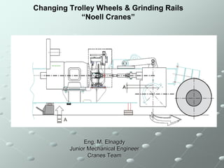
- 1. Changing Trolley Wheels & Grinding Rails “Noell Cranes” Eng. M. Elnagdy Junior Mechanical Engineer Cranes Team
- 2. Contents: * -Problem & Solution. **-Project Planning. ***-Tools. I-Wheels assembly procedures. II-Changing wheels procedures. III-Grinding the rails. Safety for Life ****-General Considerations. SCCT
- 3. Goal of the project 1-Eliminate vibration of the operator cabins. 2-Eliminate noise. 3-Healthy working to the operator. 4-No BDN during operation.
- 4. * Problem In operation and during loading and discharging containers from and to vessels, and after many crane working hours, the shape of trolley wheel and trolley rail will change. During many times of trolley movements, the trolley wheel waer from middle, and the rail have a crown at the middle and appendages at ends which results to heavy vibration and big noise. Rails original shape shape after time Solution Grinding the rails by a special machines Rail Material St70 E360 hardness brinell 205-250
- 5. Wheels The shape of the wheels changed and become with groove at middle from contact point with the rails. Which lead to damaged the bearings. Changing of wheel shape Solution Change trolley wheels Wheel Material Forging 1.6582+QT Damaged bearing
- 6. ** Planning of the projects For each crane it take from 10 to 11 days, - one day preparation. - four days changing trolley wheels and adjustment. - five or six days grinding rails
- 7. *** Tools Tool Qty Application Hydraulic jack 100 t 2 Lifting trolley Hydraulic jack 50t 2 Adjusting bearing housing center, remove gearbox support pin, and remove gear box from wheel shaft Hydraulic pump 2 Operating jacks Thread rod M24, length 50cm 2 Lifting up and down wheels Thread rod M24, length 20cm 4 Insert gearbox into wheel shaft. Nuts M24 6 For thread rods M24 (for install gearbox) Thread rod M16, length 1m 4 Extracting gearbox from wheel shaft Chain block 3 t 1 Between service crane and gearbox Small wire rope 1m length 2 Lift gearboxes and wheels shackles 2 Lifting gearboxes and wheels Lashing rope, 3m long 2 Lifting guide rollers Various lining plates 20 To put under the trolley 100x150mm, with various thickness (2,5,8,10,20,30mm) Metal plates, thickness 40mm, 4 To put between jack and trolley 50x100mm Grease type TEXCLAD2 For gearbox shaft and shrink disc Grease type EP2 For bearings Circlip lock pliers 2 For shrink disc
- 8. I- Wheel Assembly Procedures A-Gearbox Side Assembly 1- Cleaning the shaft surface 2- Insert first cover (No. 6 in drawing) cover 360/172x25 -See the seal direction (No. 11 in drawing) -Seal No. 170x200x15
- 9. 3-Heating the bearing (No. 10 in drawing), -bearing type: spherical roller bearing -bearing No. 23230 -using SKF induction heater (type TIH 100m). -heating temperature 160 C. 4-Insert the bearing in its position. -insert bearing must be fast. -must wear heater gloves.
- 10. 5-Insert bearing housing (No. 4 in drawing). -housing must be cleaned by soft grinding machine. 6-Insert distance bush 170/136x57 (No. 3 in drawing)
- 11. 7-Insert second cover (No. 5 in drawing). -cover 360/172x25 -see seal direction
- 12. B- Another Side 1-Insert first cover (No. 7 in drawing) -cover 360/172x25. -see seal direction 2-Heating the bearing
- 13. 3-Insert the bearing. -wearing a special gloves 4-Insert washer plate (No. 9 in drawing). -PL 15x180x180
- 14. 5-Insert bearing housing. -housing must be cleaned by soft grinding machine. 6-Insert second (No, 8 in drawing). -cover 360x22
- 15. II- Changing Wheels Procedures 1-Bring the Trolley under the M- house, so that the WS- wheels standing under the covers and we can using the M- house crane. 2-Under the trolley, between the rail and the trolley traveling girder one hydraulic jack 100t under the jacking point- only make strong not lifting. 3-Check everywhere, also underneath the girder is free.
- 16. 4-Loose all screw of the guide roller support, and remove them. 5-Dismantle the cardan shaft on the gear box and the torque support- the gearbox is secured on the hook of the M-house crane. Torque support jack 50t Cardan shaft
- 17. 6-Dissolve the shrink disc. *shrink disc components. 7-Pull off the gearbox. Jack 50t thread rod M16
- 18. 8-Dismantle on both sides of the bearing plates- in and outside. 9-Lift up the trolley, so high that we can rolling out the wheel. Before secure the wheel by sling at the hook of the M-house crane.
- 19. 10-Bring the dismantled wheel on the ground and lift a new one- mount it- put the trolley again on the rail. 11-Amount again bearing plates, torque support, cardan shaft, gearbox, and shrink disc. *before amount shrink disc, shaft must be cleaned and put black grease as see *amount the gearbox using thread rod M24, length 20cm, and nut 24
- 20. III- Grinding the rail -Grinding the rail is carried out by two special grinding machine mounted and driven by trolley. -The electrical supply from machinery house. -The trolley moves by maintenance speed (from maintenance panel on the trolley). -Thickness of erased layer of the rail by grinding Max. 2mm
- 21. -Grinding the rails take from 5 to 6 days, depend on rail status. Grinding the rails from side. Grinding the rails from top.
- 22. -Grinding the rails at beginning (grinding part is thin). -Grinding the rail at finish (grinding part from 87:90 % of rail face)
- 23. -Grinding the rail at hinge point at start of grinding. -Grinding the rail at hinge point at finishing of grinding -Difference between start of grinding and finishing
- 24. General consideration *Before Start trolley wheels changing: 1-Secure the area under the crane by safety cones. 2-Check maintenance crane of the crane. 3-Check bolts of machinery house for maintenance crane. *Adjustment of wheel 1-Lift the trolley by hydraulic jack (100t). 2-Put the hydraulic jack (50t) under point (2) to rotate the housing to be the point (1) at same level with point (3). 3-After finishing the adjustment of four wheels, move the trolley forward and backward, and see the contact of the wheels with the rail 4-If there is any deviation of the wheel, lift the trolley up and move the point (2) up little pit and repeat again until the wheel adjusted. *When assembly the gear box, you must not put any grease on the shaft (at shrink disc area). (3) (1) (2)
- 25. *Before Grinding the rail: -Adjustment of rail level at hinge point by butting chimes between boom and girder (thickness between 0.5 to 1 mm). girder boom *After grinding the rail: -Cleaning the rail ,girder, and boom. & operation test.