SlideShare uma empresa Scribd logo
1 de 29
CHAPTER 6
MANUFACTURING SYSTEM
1.0 Introduction to Manufacturing Systems
We define a manufacturing system is a collection of integrated equipment and human
resources, whose function is to perform one or more processing and/or assembly
operations on a starting raw material, part, or set of parts. The integrated equipment
includes production machines and tools, material handling and work positioning devices,
and computer systems. Human resources are required either full time or periodically to keep
the system running. The manufacturing system is where the value-added work is
accomplished on the part or product. The position of the manufacturing system in the larger
production system is shown in Figure 1.
Figure 1: The position of the manufacturing system in the larger
production system.
The manufacturing systems include:
• one worker tending one machine, which operates on semi-automatic cycle
• a cluster of semi-automatic machines, attended by one worker
• a fully automated assembly machine, periodically attended by a human worker
• a group of automated machines working on automatic cycles to produce a family of
similar parts
• a team of workers performing assembly operations on a production line.
1
In the present chapter, we classify these manufacturing systems and examine their
features and performance. In other chapters in this part of the book, we discuss the
various manufacturing systems of greatest commercial and technological importance
1.1 COMPONENTS OF A MANUFACTURING SYSTEM
A manufacturing system consists of several components. In a given system, these
components usually include:
• production machines plus tools, fixtures, and other related hardware
• material handling system
• computer systems to coordinate and/or control the above components
• human workers
1.1.1 Production Machines
In virtually all modern manufacturing systems, most of the actual processing or
assembly work is accomplished by machines or with the aid of tools. The
machines can be classified as:
(1) manually operated,
(2) semi-automated, or
(3) fully automated.
Manually operated machines are directed or supervised by a human worker.
The machine provides the power for the operation and the worker provides the
control. Conventional machine tools (e.g., lathes, milling machines, drill presses)
fit into this category. The worker must be at the machine continuously.
A semi-automated machine performs a portion of the work cycle under some
form of program control, and a human worker tends to the machine for the
remainder of the cycle, by loading and unloading it or performing some other task
each cycle. An example of this category is a CNC lathe controlled for most of the
work cycle by the part program, but requiring a worker to unload the finished part
and load the next workpiece at the end of the part program. In these cases, the
2
worker must attend to the machine every cycle, but continuous presence during
the cycle is not always required. If the automatic machine cycle takes, say, 10
min, while the part unloading and loading portion of the work cycle only takes 1
min, then there may be an opportunity for one worker to tend more than one
machine.
A fully automated machine is its capacity to operate for extended periods of time
with no human attention. By extended periods of time, we generally mean longer
than one work cycle. A worker is not required to be present during each cycle.
Instead, the worker may need to tend the machine every tenth cycle or every
hundredth cycle. An example of this type of operation is found in many injection
molding plants, where the molding machines run on automatic cycle, but
periodically the collection bin full of molded parts at the machine must be taken
away and replaced by an empty bin.
1.1.2 Material Handling System
In most processing and assembly operations performed on discrete parts and
products, the following ancillary functions must be provided:
(1) loading and unloading work units
(2) positioning - the work units at each station.
(3) transporting
These functions are accomplished by the material handling system. Most
material handling systems used in production also provide
(4) a temporary storage function.
The purpose of storage in these systems is usually to make sure that work is
always present for the stations, that is, that the stations are not starved (meaning
that they have nothing to work on).
1.1.3 Computer Control System
In today's automated manufacturing systems, a computer is required to control the
automated and semi-automated equipment and to participate in the overall
coordination and management of the manufacturing system. Even in manually
driven manufacturing systems, such as a completely manual assembly line, a
computer system is useful to support production. Typical computer system
functions include the following:
3
• Communicate instructions to workers.
In manually operated workstations that perform different tasks on different work
units, processing or assembly instructions for the specific work unit must be
communicated to the operator.
• Download part programs to computer-controlled machines (e.g., CNC machine
tools).
• Material handling system control.
This function is concerned with controlling the material handling system and
coordinating its activities with those of the workstations.
• Schedule production.
Certain production scheduling functions are accomplished at the site of the
manufacturing system.
• Failure diagnosis.
This involves diagnosing equipment malfunctions, preparing preventive
maintenance schedules, and maintaining spare parts inventory.
• Safety Monitoring.
This function ensures that the system does not operate in an unsafe condition.
The goal of safety monitoring is to protect both the human workers manning the
system and the equipment comprising the system.
• Quality Control.
The purpose of this control function is to detect and possibly reject defective work
units produced by the system.
• Operations management.
Managing the overall operations of the manufacturing system, either directly (by
supervisory computer control) or indirectly (by preparing the necessary reports
for management personnel).
1.1.4 Human Resources
4
In many manufacturing systems, humans perform some or all of the value-added
work that is accomplished on the parts or products. In these cases, the human
workers are referred to as direct labor. Through their physical labor, they directly
add to the value of the work unit by performing manual work on it or by controlling
the machines that perform the work. In manufacturing systems that are fully
automated, direct labor is still needed to perform such activities as loading and
unloading parts to and from the system, changing tools, resharpening tools, and
similar functions. Human workers are also needed for automated manufacturing
systems to manage or support the system as computer programmers, computer
operators, part programmers for CNC machine tools , maintenance and repair
personnel, and similar indirect labor tasks..
1.2 CLASSIFICATION OF MANUFACTURING SYSTEMS
There are the variety of manufacturing system types and develop a classification based
on factors. The factors are:
(1) types of operations performed,
(2) number of workstations and system layout,
(3) level of automation,
(4) part or product variety.
The four factors in manufacturing systems classification scheme are defined in Table 2.
TABLE 2: Factors in Manufacturing Systems Classification Scheme
1.2.1 Types of Operations Performed
5
Manufacturing systems are distinguished by the types of operations they perform
such as
(1) processing operations on individual work units
(2) assembly operations to combine individual parts into assembled entities.
1.2.2 Number of Workstations and System Layout
The number of workstations is a key factor in the classification scheme. It exerts a
strong influence on the performance of the manufacturing system in terms of production
capacity, productivity, cost per unit, and maintainability.
More stations mean that the system is more complex and therefore more difficult to
manage and maintain. The system consists of more workers, more machines, and more
parts being handled. The logistics and coordination of the system becomes more
involved. Maintenance problems occur more frequently. Closely related to number of
workstations is the arrangement of the workstations, that is, the way the stations are laid
out. This, of course, applies mainly to systems with multiple stations.
The classification scheme is applicable to manufacturing systems that perform either
processing or assembly operations. Although these operations are different, the
manufacturing systems to perform them possess similar configurations. According to
number of stations and the layout of the stations, the classification scheme has three
levels:
Type I Single station.
This is the simplest case, consisting of one workstation (n = 1), usually including a
production machine that can be manually operated, semi automated, or fully
automated.
Type II Multiple stations with variable routing.
This manufacturing system consists of two or more stations (n > 1) that are
designed and arranged to accommodate the processing or assembly of different
part or product styles.
Type III Multiple stations with fixed routing.
6
This system has two or more workstations (n > 1), which are laid out as a
production line.
1.2.3 Level of Automation
The level of automation is another factor that characterizes the Manufacturing system.
As defined above, the workstations (machines) in a manufacturing system can be
manually operated, semi-automated, or fully automated.
1.2.4 Part or Product Variety
A fourth factor that characterizes a manufacturing system is the degree to which it is
capable of dealing with variations in the parts or products it produces. Examples of
possible variations that a manufacturing system may have to cope with include:
• variations in type and/or color of plastic of molded parts in injection molding
• variations in electronic components placed on a standard size printed circuit board
• variations in the size of printed circuit boards handled by a component placement
machine
• variations in geometry of machined parts
• variations in parts and options in an assembled product on a final assembly line.
2.0 FLEXIBLE MANUFACTURING SYSTEMS
WHAT IS AN FMS?
Flexible Manufacturing System (FMS) is a highly automated GT machine cell, consist-
ing of a group of processing workstations (usually CNC machine tools), interconnected
by an automated material handling and storage system, and controlled by a distributed
computer system.
The FMS is most suited for the mid-variety, mid-volume production range (refer to type
of flexible automation).
The initials FMS are sometimes used to denote the term flexible machining system.
7
The machining process is presently the largest application area for FMS technology.
However, it seems appropriate to interpret FMS in its broader meaning, allowing for a
wide range of possible applications beyond machining.
An FMS relies on the principles of group technology. No manufacturing system can be
completely flexible. There are limits to the range of parts or products that can be made in
an FMS.
What Makes It Flexible?
There are three identified capabilities that a manufacturing system must possess to be
flexible:
i. the ability to identify and distinguish among the different part or product styles
processed by the system,
ii. quick changeover of operating instructions, and
iii. quick changeover of physical setup.
Flexibility is an attribute that applies to both manual and automated systems. In manual
systems, the human workers are often the enablers of the system's flexibility.
To develop the concept of flexibility in an automated manufacturing system, consider a
machine cell consisting of two CNC machine tools that are loaded and unloaded by an
industrial robot from a parts carousel.
8
The cell operates unattended for extended periods of time. Periodically, a worker
unload completed parts from the carousel and replace them with new workparts. By
definition, this is an automated manufacturing cell, but is it a flexible manufacturing
cell? One might argue that yes, it is flexible, since the cell consists of CNC machine
tools, and CNC machines are flexible because they can be programmed to machine
different part configurations. However, if the cell only operates in a batch mode, in
which the same part style is produced by both machines in lots of several dozen (or
several hundred) units, then this does not qualify as flexible manufacturing.
To qualify as being flexible, a manufacturing system should satisfy several criteria. The
following are four reasonable tests of flexibility in an automated manufacturing system:
i. Part variety test.
Can the system process different part styles in a non-batch mode?
ii. Schedule change test.
Can the system readily accept changes in production schedule, and changes in
either part mix or production quantities?
iii. Error recovery test.
Can the system recover gracefully from equipment malfunctions and breakdowns,
so that production is not completely disrupted?
iv. New part test.
Can new part designs be introduced into the existing product mix with relative
ease?
9
If the answer to all of these questions is "yes" for a given manufacturing system, then
the system can be considered flexible. If the automated system does not meet at
least the first three tests, it should not be classified as an FMS.
Types of FMS
Types of Flexibility in Manufacturing
Comparison of four criteria of flexibility in a Manufacturing System and the seven types
of flexibility.
10
FMS can be distinguished according to the kinds of operations such as:
i. processing operations
ii. assembly operation
FMS can be classified into two:
i. number of machines
ii. level of flexibility
Number of Machines
i. Typical categories:
A Single Machine Cell (SMC)
Consists of one CNC machining center combined with a parts storage system for
unattended operation. Completed parts are periodically unloaded from the parts
storage unit, and raw workparts are loaded into it. The cell can be designed to operate
in either a batch mode or a flexible mode or in combinations of the two. When
operated in a batch mode, the machine processes parts of a single style in specified
lot sizes and is then changed over to process a batch of the next part style. When
operated in a flexible mode, the system satisfies three of the four flexibility tests:
11
(1) processing different part styles,
(2) responding to changes in production schedule, and
(4) accepting new part introductions.
Criterion (3), error recovery, cannot be satisfied because if the single machine breaks
down, production stops.
A Single Machine Cell – Consists of one machining CNC center and part storage
unit
A Flexible Manufacturing Cell (FMC)
Consists of two or three processing workstations (typically CNC machining centers or
turning centers) plus a part handling system. The part handling system is connected to
a load/unload station. In addition, the handling system usually includes a limited parts
storage capacity. A flexible manufacturing cell satisfies the four flexibility tests.
12
A Flexible Manufacturing Cell – Consists of three identical processing stations
( CNC, Load/Unload station and part handling system)
A Flexible Manufacturing System (FMS)
Has four or more processing workstations connected mechanically by a common part
handling system and electronically by a distributed computer system. The different
between an FMS and an FMC:
i. the number of machines: an FMC has two or three machines, while an FMS has
four or more.
ii. the FMS generally includes non-processing workstations that support production
but do not directly participate in it. These other stations include part/pallet
washing stations, coordinate measuring machines, and so on.
iii. the computer control system of an FMS is generally larger and more so-
phisticated, often including functions not always found in a cell, such as
diagnostics and tool monitoring. These additional functions are needed more in an
FMS than in an FMC because the FMS is more complex.
The characteristics of the three categories of flexible manufacturing cells and systems
are summarized:
13
Features of the three categories of the flexible cells and system
Flexibility Criteria Applied to the Three Types of Manufacturing Cells and System
Level of Flexibility.
Another classification of FMS is according to the level of flexibility designed into the
system. This method of classification can be applied to systems with any number of
workstations, but its application seems most common with FMCs and FMSs
i. dedicated FMS
ii. random-order FMS
A dedicated FMS is designed to produce a limited variety of part styles, and the com-
plete universe of parts to be made on the system is known in advance. The part family
14
is likely to be based on product commonality rather than geometric similarity. The
product design is considered stable, and so the system can be designed with a certain
amount of process specialization to make the operations more efficient.
A random-order FMS is more appropriate when the part family is large, there are sub-
stantial variations in part configurations, there will be new part designs introduced into
the system and engineering changes in parts currently produced, and the production
schedule is subject to change from day-to-day. To accommodate these variations, the
random-order FMS must be more flexible than the dedicated FMS. It is equipped with
general-purpose machines to deal with the variations in product and is capable of pro-
cessing parts in various sequences (random-order). A more sophisticated computer
control system is required for this FMS type.
The dedicated FMS is less flexible but more capable of higher production rates. The
random-order FMS is more flexible but at the price of lower production rates. A
comparison and comparisons of the features of these two FMS types is shown as
below.
15
Comparison between dedicated and random order FMS types
Flexibility Criteria Applied to Dedicated and Random Order FMS
FMS COMPONENTS
There are four basic components of an FMS:
i. workstations
ii. material handling and storage system
iii. computer control system
iv. workers/operators
Workstations
The processing or assembly equipment used in an FMS depends on the type of work
accomplished by the system. In a system designed for machining operations, the
principle types of processing station are CNC machine tools. However, the FMS
concept is also applicable to various other processes as well. Following are the types
of workstations typically found in an FMS.
Load/Unload Stations.
The load/unload station is the physical interface between the FMS and the rest of the
factory. Raw workparts enter the system at this point, and finished parts exit the
system from here. Loading and unloading can be accomplished either manually or by
automated handling systems. Manual loading and unloading is prevalent in most FMSs
today. The load/unload station should be ergonomically designed to permit convenient
and safe movement of workparts. For parts that are too heavy to lift by the operator,
16
mechanized cranes and other handling devices are installed to assist the operator. A
certain level of cleanliness must be maintained at the workplace, and air hoses or
other washing facilities are often required to flush away chips and ensure clean
mounting and locating points. The station is often raised slightly above floor level using
an open-grid platform to permit chips and cutting fluid to drop through the openings for
subsequent recycling or disposal.
The load/unload station should include a data entry unit and monitor for communi-
cation between the operator and the computer system. Instructions must be given to
the operator regarding which part to load onto the next pallet to adhere to the
production schedule. When the part loading procedure has been completed, the han-
dling system must proceed to launch the pallet into the system.
Machining Stations.
The most common applications of FMSs are machining operations. The workstations
used in these systems are therefore predominantly CNC machine tools. Most common
is the CNC machining center. CNC machining centers possess features that make
them compatible with the FMS, including automatic tool changing and tool storage, use
of palletized workparts, CNC, and capacity for distributed numerical control (DNC).
Machining centers can be ordered with automatic pallet changers that can be readily
interfaced with the FMS part handling system. Machining centers are generally used
for nonrelational parts. For rotational parts, turning centers are used; and for parts
that are mostly rotational but require multitooth rotational cutters (milling and drilling),
mill-turn centers can be used.
In some machining systems, the types of operations performed are concentrated in a
certain category, such as milling or turning. For milling, special milling machine
modules can be used to achieve higher production levels than a machining center is
capable of. The milling module can be vertical spindle, horizontal spindle, or multiple
spindle. For turning operations, special turning modules can be designed for the FMS
Other Processing Stations.
The FMS concept has been applied to other processing operations in addition to
machining. One such application is sheet metal fabrication processes. The processing
workstations consist of pressworking operations, such as punching, shearing, and
certain bending and forming processes.
17
Assembly.
Some FMSs are designed to perform assembly operations. Flexible automated
assembly systems are being developed to replace manual labor in the assembly of
products typically made in batches. Industrial robots are often used as the automated
workstations in these flexible assembly systems.
Other Stations and Equipment.
Inspection can be incorporated into an FMS, either by including an inspection
operation at a processing workstation or by including a station specifically designed for
inspection. Coordinate measuring machines, special inspection probes that can be
used in a machine tool spindle, and machine vision are three possible technologies for
performing inspection on an FMS. Inspection has been found to be particularly
important in flexible assembly systems to ensure that components have been properly
added at the workstations.
Material Handling and Storage System
The second major component of an FMS is its material handling and storage system.
Functions of the Handling System.
The material handling and storage system in an FMS performs the following functions:
• Random, independent movement of work-parts between stations. This
means that parts must be capable of moving from any one machine in the system
to any other machine, to provide various routing alternatives for the different parts
and to make machine substitutions when certain stations are busy.
• Handle a variety of work-part configurations. For prismatic parts, this is
usually accomplished by using modular pallet fixtures in the handling system.
The fixture is located on the top face of the pallet and is designed to
accommodate different part configurations by means of common components,
quick-change features, and other devices that permit a rapid build-up of the
fixture for a given part. The base of the pallet is designed for the material
handling system. For rotational parts, industrial robots are often used to load and
unload the turning machines and to move parts between stations.
• Temporary storage. The number of parts in the FMS will typically exceed the
18
number of parts actually being processed at any moment. Thus, each station has
a small queue of parts waiting to be processed, which helps to increase machine
utilization.
• Convenient access for loading and unloading work-parts. The handling
system must include locations for load/unload stations.
• Compatible with computer control. The handling system must be capable of
being controlled directly by the computer system to direct it to the various
workstations, load/unload stations, and storage areas.
Material Handling Equipment.
The types of material handling systems used to transfer parts between stations in an
FMS include a variety of conventional material transport equipment, in-line transfer
mechanisms, and industrial robots. The material handling function in an FMS is often
shared between two systems:
(1) a primary handling system and
(2) a secondary handling system.
The primary handling system establishes the basic layout of the FMS and is
responsible for moving workparts between stations in the system.
The secondary handling system consists of transfer devices, automatic pallet
changers, and similar mechanisms located at the workstations in the FMS. The
function of the secondary handling system is to transfer work from the primary system
to the machine tool or other processing station and to position the parts with sufficient
accuracy and repeatability to perform the processing or assembly operation.
The primary handling system is sometimes supported by an automated storage sys-
tem and integrated with an automated storage/retrieval system (AS/RS), and the S/R
machine serves the work handling function for the workstations as well as delivering
parts to and from the storage racks.
Computer Control System
The FMS includes a distributed computer system that is interfaced to the
19
workstations, material handling system, and other hardware components. A typical
FMS computer system consists of a central computer and microcomputers
controlling the individual machines and other components. The central computer
coordinates the activities of the components to achieve smooth overall operation of
the system. Functions performed by the FMS computer control system can be
grouped into the following categories:
1. Workstation control.
In a fully automated FMS, the individual processing or assembly stations
generally operate under some form of computer control. For a machining
system, CNC is used to control the individual machine tools.
2. Distribution of control instructions to workstations.
Some form of central intelligence is also required to coordinate the processing
at individual stations. In a machining FMS, part programs must be downloaded
to machines, and DNC is used for this purpose. The DNC system stores the
programs, allows submission of new programs and editing of existing programs
as needed, and performs other DNC functions.
3. Production control.
The part mix and rate at which the various parts are launched into the system
must be managed. Input data required for production control includes desired
daily production rates per part, numbers of raw workparts available, and number
of applicable pallets. The production control function is accomplished by routing
an applicable pallet to the load/unload area and providing instructions to the
operator for loading the desired workpart.
4. Traffic control. This refers to the management of the primary material handling
system that moves workparts between stations. Traffic control is accomplished
by actuating switches at branches and merging points, stopping parts at machine
tool transfer locations, and moving pallets to load/unload stations.
5. Shuttle control.
This control function is concerned with the operation and control of the secondary
handling system at each workstation. Each shuttle must be coordinated with the
primary handling system and synchronized with the operation of the machine tool
it serves.
6. Workpiece monitoring.
The computer must monitor the status of each cart and/or pallet in the primary
20
and secondary handling systems as well as the status of each of the various
workpiece types.
7. Tool control.
In a machining system, cutting tools are required. Tool control is concerned with
managing two aspects of the cutting tools:
• Tool location.
This involves keeping track of the cutting tools at each workstation. If one or
more tools required to process a particular workpiece is not present at the
station that is specified in the part's routing, the tool control subsystem takes
one or both of the following actions: (a) determines whether an alternative
workstation that has the required tool is available and/or (b) notifies the
operator responsible for tooling in the system that the tool storage unit at the
station must be loaded with the required cutter(s).
• Tool life monitoring.
In this aspect of tool control, a tool life is specified to the computer for each
cutting tool in the FMS. A record of the machining time usage is maintained
for each of the tools, and when the cumulative machining time reaches the
specified life of the tool, the operator is notified that a tool replacement is
needed.
8. Performance monitoring and reporting.
The computer control system is programmed to collect data on the operation and
performance of the FMS. This data is periodically summarized, and reports are
prepared for management on system performance.
9. Diagnostics.
This function is available to a greater or lesser degree on many manufacturing
systems to indicate the probable source of the problem when a malfunction
occurs. It can also be used to plan preventive maintenance in the system and to
identify impending failures. The purpose of the diagnostics function is to reduce
breakdowns and downtime and increase availability of the system.
Human Resources
One additional component in the FMS is human labor. Humans are needed to
manage the operations of the FMS. Functions typically performed by humans
include:
21
(1) loading raw workparts into the system,
(2) unloading finished parts (or assemblies) from the system,
(3) changing and setting tools,
(4) equipment maintenance and repair,
(5) NC part programming in a machining system,
(6) programming and operating the computer system, and
(7) overall management of the system.
FMS benefits
A number of benefits can be expected in successful FMS applications. The principal
benefits are the following:
• Increased machine utilization. FMSs achieve a higher average utilization than
machines in a conventional batch production machine shop. Reasons for this
include:
24 hr/day operation, automatic tool changing at machine tools, automatic pallet
changing at workstations, queues of parts at stations, and dynamic scheduling of
production that takes into account irregularities from normal operations. It should
be possible to approach 80-90% asset utilization by implementing FMS
technology
• Fewer machines required. Because of higher machine utilization, fewer
machines are required.
• Reduction in factory floor space required. Compared with a job shop of
equivalent capacity, an FMS generally requires less floor area. Reductions in floor
space requirements are estimated to be 40-50%
• Greater responsiveness to change. An FMS improves response capability to part
design changes, introduction of new parts, changes in production schedule and
product mix, machine breakdowns, and cutting tool failures. Adjustments can be
made in the production schedule from one day to the next to respond to rush
orders and special customer requests.
22
• Reduced inventory requirements. Because different parts are processed
together rather than separately in batches, work-in-process (WIP) is less than in a
batch production mode. The inventory of starting and finished parts can be
reduced as well. Inventory reductions of 60-80% are estimated.
• Lower manufacturing lead times. Closely correlated with reduced WIP is the time
spent in process by the parts. This means faster customer deliveries.
• Reduced direct labor requirements and higher labor productivity. Higher
production rates and lower reliance on direct labor translate to greater productivity
per labor hour with an FMS than with conventional production methods. Labor
savings of 30-50% are estimated.
• Opportunity for unattended production. The high level of automation in an FMS
allows it to operate for extended periods of time without human attention. In the
most optimistic scenario, parts and tools are loaded into the system at the end of
the day shift, and the FMS continues to operate throughout the night so that the
finished parts can be unloaded the next morning.
MANUAL ASSEMBLY SYSTEM
A Manual Assembly Line is a production line that consists of a sequence of
workstations where assembly tasks are performed by human workers. Products
are assembled as they move along the line. A mechanized material transport
system is typically used to move the base part along the line as it is gradually
transformed into the final product. However, in some manual lines, the product is
simply moved manually from station-to-station. The production rate of an
assembly line is determined by its slowest station. Stations capable of working
faster are ultimately limited by the slowest station.
23
Products Usually Made on Manual Assembly Lines
Typical assembly operations performed at stations on a manual assembly line
Assembly Workstations
A workstation on a manual assembly line is a designated location along the work
flow path at which one or more work elements are performed by one or more
workers. The work elements represent small portions of the total work that must be
accomplished to assemble the product.
Some workstations are designed for workers to stand, while others allow the workers
to sit. When the workers stand, they can move about the station area to perform
their assigned task. This is common for assembly of large products, such as cars,
trucks, and major appliances. The typical case is when the product is moved by a
conveyor at constant velocity through the station. The worker begins the assembly
24
task near the upstream side of the station and moves along with the work unit until
the task is completed, then walks back to the
Reasons for Manual Assembly
• Specialization of labor.
This principle asserts that when a large job is divided into small tasks and each task
is assigned to one worker, the worker becomes highly proficient at performing the
single task. Each worker becomes a specialist. One of the major explanations of
specialization of labor is the learning curve*.
• Interchangeable parts
in which each component is manufactured to sufficiently close tolerances that any
part of a certain type can be selected for assembly with its mating component.
Without inter-changeable parts, assembly would require filing and fitting of mating
components, rendering assembly line methods impractical.
• Work principle in material handling, which provides that each work unit flows
smoothly through the production line, traveling minimum distances between
stations.
Principle 3. work principle: Material handling work should be minimized without
sacrificing productivity or the level of service required of the operation.
• The measure of material handling work is flow rate (volume, weight, or count per
unit of time) multiplied by distance moved.
• Consider each pickup and set-down, or placing material in and out of storage, as
distinct moves and components of the distance moved.
• Simplifying processes by reducing, combining, shortening, or eliminating
unnecessary moves will reduce work.
• Where possible, gravity should be used to move materials or to assist in their
movement while respecting consideration of safety and the potential for product
damage.
• The Work Principle applies universally, from mechanized material handling in a
factory to over-the-road trucking.
25
• The Work Principle is implemented best by appropriate layout planning: locating the
production equipment into a physical arrangement corresponding to the flow of
work. This arrangement tends to minimize the distances that must be traveled by
the materials being processed.
• Line pacing. Workers on an assembly line are usually required to complete their
assigned tasks on each product unit within a certain cycle time, which paces the
line to maintain a specified production rate. Pacing is generally implemented by
means of a mechanized conveyor.
* Learning curve
Is a phenomenon virtually occurs in all manufacturing system. It applies to any
repetitive activity. It is happened when the cycle time required to perform a given
activity decreases as the number of cycles increases.
The learning curve phenomenon
According to learning curve theory, there is a constant learning rate that applies to
a given task. Different learning rates are associated with different types of tasks.
And different workers have different learning capabilities that affect the learning
rate. Whatever the learning rate, its effect is most identifiable every time the
number of units doubles. Assuming a learning rate of 80%, the time to produce
the second unit is 80% of that for the first unit the time to produce the fourth unit is
80% of that for the second; and so forth. Every time the number of units doubles,
the task time per unit has been reduced to 80% of its previous value. Between
26
these points, the unit task times gradually decrease. We can calculate the
expected time for the Nth work unit by means of the following equation:
TN = T1(N)m
where TN = task time for the Nth unit of work; T1 = task time for the first work unit
N = the number of the unit produced in the series; and m = an exponent that
depends or the learning rate. The value of m can be determined as follows:
m = ln(LR)
ln (2 )
where LR = learning rate, expressed as a decimal fraction, such as 0.80. The
natural logarithm of 2 in the denominator manifests the doubling effect of the
learning rate. This causes the curve to plot as a straight line in a log-log graph.
EXAMPLE
A certain mechanical assembly task required 3.75 min to complete when a skilled
worker did it for the first time. The task will be performed on an assembly line
used to produce 1000 units of a particular product. The line is currently operating
on a pilot basis, while workers are learning their respective tasks. The line will run
on this basis for 50 units, after which it will go into regular production.
a) If the learning rate for tasks of this type is 84%, what will the task time
be for the 50th
unit
b) For the 1000th
unit?
Solution:
a) to determine the task time for any numbered unit, we need to compute the
exponent m,
m = ln (0.84) = -0.2515
ln (2)
27
The task time for the 50th
unit is,
T50 = 3.75(50) –0.2515
= 3.75(0.3738) = 1.402 min
b) The task time for the 1000th
unit
T1000 = 3.75(1000) –0.2515
= 0.660 min
AUTOMATED MANUFACTURING SYSTEMS
Automated Production Lines require a significant capital investment. It is an example
of fixed automation, where it is difficult to alter the sequence and content of the
processing operations. The application is appropriate under the conditions:
i. High product demand
ii. Stable product design
iii. Long product life
iv. Multiple operations
The benefits of Automated Production Lines:
i. low direct labour content
ii. low product cost
iii. production lead time reduced/minimized
iv. factory floor space minimized
Fundamentals of Automated Production Lines (APL)
APL consists of multiple workstation that are linked together by a work handling system
that transfers parts from one station to other station.
28
Each station performs a different operation, so that the sum total of of all operations is
required to complete one unit of work.
29

Mais conteúdo relacionado

Mais procurados

Group technology, Production flow Analysis
Group technology, Production flow AnalysisGroup technology, Production flow Analysis
Group technology, Production flow AnalysisKEERTHIVASAN RAVI
 
Flexible manufacturing systems (FMS)
Flexible manufacturing systems (FMS)Flexible manufacturing systems (FMS)
Flexible manufacturing systems (FMS)jntuhcej
 
Flexible Manufacturing System
Flexible Manufacturing SystemFlexible Manufacturing System
Flexible Manufacturing SystemAkhtar Kamal
 
Process Planning
Process PlanningProcess Planning
Process PlanningGuhan M
 
COMPONENTS OF CIM
COMPONENTS OF CIM COMPONENTS OF CIM
COMPONENTS OF CIM manimaran m
 
Computer Aided Process Planning (CAPP)
Computer Aided Process Planning (CAPP)Computer Aided Process Planning (CAPP)
Computer Aided Process Planning (CAPP)Pratik Gandhi
 
COMPUTER AIDED PROCESS PLANNING (CAPP)
COMPUTER AIDED PROCESS PLANNING (CAPP)COMPUTER AIDED PROCESS PLANNING (CAPP)
COMPUTER AIDED PROCESS PLANNING (CAPP)Victor Al
 
Automated assembly systems
Automated assembly systemsAutomated assembly systems
Automated assembly systemsVibhas Purushu
 
Computer-Aided Assembly Planning
Computer-Aided Assembly PlanningComputer-Aided Assembly Planning
Computer-Aided Assembly PlanningRichard Farr
 
Single-Station Manufacturing Cells
Single-Station Manufacturing CellsSingle-Station Manufacturing Cells
Single-Station Manufacturing CellsVADLAJAGADEESHWARAAC
 
Flexible manufacturing systems (FMS)
Flexible manufacturing systems (FMS)Flexible manufacturing systems (FMS)
Flexible manufacturing systems (FMS)SERCOD
 
Uint 1 locating and clamping devices
Uint 1 locating and clamping devicesUint 1 locating and clamping devices
Uint 1 locating and clamping devicesS.DHARANI KUMAR
 
Automated Assembly Systems
Automated Assembly SystemsAutomated Assembly Systems
Automated Assembly Systemschethan kumar
 
Computer aided manufacturing
Computer aided manufacturingComputer aided manufacturing
Computer aided manufacturingGulfaraz alam
 
COMPUTER AIDED PROCESS PLANNING
COMPUTER AIDED PROCESS PLANNINGCOMPUTER AIDED PROCESS PLANNING
COMPUTER AIDED PROCESS PLANNINGjntuhcej
 
Chapter 1 introduction to manufacturing system
Chapter 1   introduction to manufacturing systemChapter 1   introduction to manufacturing system
Chapter 1 introduction to manufacturing systemN. A. Sutisna
 

Mais procurados (20)

Group technology, Production flow Analysis
Group technology, Production flow AnalysisGroup technology, Production flow Analysis
Group technology, Production flow Analysis
 
Flexible manufacturing systems (FMS)
Flexible manufacturing systems (FMS)Flexible manufacturing systems (FMS)
Flexible manufacturing systems (FMS)
 
Flexible Manufacturing System
Flexible Manufacturing SystemFlexible Manufacturing System
Flexible Manufacturing System
 
Process Planning
Process PlanningProcess Planning
Process Planning
 
COMPONENTS OF CIM
COMPONENTS OF CIM COMPONENTS OF CIM
COMPONENTS OF CIM
 
Computer Aided Process Planning (CAPP)
Computer Aided Process Planning (CAPP)Computer Aided Process Planning (CAPP)
Computer Aided Process Planning (CAPP)
 
COMPUTER AIDED PROCESS PLANNING (CAPP)
COMPUTER AIDED PROCESS PLANNING (CAPP)COMPUTER AIDED PROCESS PLANNING (CAPP)
COMPUTER AIDED PROCESS PLANNING (CAPP)
 
Automated assembly systems
Automated assembly systemsAutomated assembly systems
Automated assembly systems
 
Group Technology
Group TechnologyGroup Technology
Group Technology
 
Computer-Aided Assembly Planning
Computer-Aided Assembly PlanningComputer-Aided Assembly Planning
Computer-Aided Assembly Planning
 
CNC Machines and its Components
CNC Machines and its ComponentsCNC Machines and its Components
CNC Machines and its Components
 
Single-Station Manufacturing Cells
Single-Station Manufacturing CellsSingle-Station Manufacturing Cells
Single-Station Manufacturing Cells
 
Flexible manufacturing systems (FMS)
Flexible manufacturing systems (FMS)Flexible manufacturing systems (FMS)
Flexible manufacturing systems (FMS)
 
Uint 1 locating and clamping devices
Uint 1 locating and clamping devicesUint 1 locating and clamping devices
Uint 1 locating and clamping devices
 
Automated Assembly Systems
Automated Assembly SystemsAutomated Assembly Systems
Automated Assembly Systems
 
Design For Assembly
Design For AssemblyDesign For Assembly
Design For Assembly
 
Computer aided manufacturing
Computer aided manufacturingComputer aided manufacturing
Computer aided manufacturing
 
Nc Machine
Nc MachineNc Machine
Nc Machine
 
COMPUTER AIDED PROCESS PLANNING
COMPUTER AIDED PROCESS PLANNINGCOMPUTER AIDED PROCESS PLANNING
COMPUTER AIDED PROCESS PLANNING
 
Chapter 1 introduction to manufacturing system
Chapter 1   introduction to manufacturing systemChapter 1   introduction to manufacturing system
Chapter 1 introduction to manufacturing system
 

Destaque

4.types of manufacturing system and layouts
4.types of manufacturing system and layouts4.types of manufacturing system and layouts
4.types of manufacturing system and layoutsAkash Bakshi
 
Chapter 1 introduction to automation
Chapter 1   introduction  to automationChapter 1   introduction  to automation
Chapter 1 introduction to automationMohamad Sahiedan
 
Manufacturing systems
Manufacturing systemsManufacturing systems
Manufacturing systemsAbu Bashar
 
FLEXIBLE MANUFACTURING SYSTEM
FLEXIBLE MANUFACTURING SYSTEMFLEXIBLE MANUFACTURING SYSTEM
FLEXIBLE MANUFACTURING SYSTEMAnand Khare
 
types of production system
types of production systemtypes of production system
types of production systempakkiaarzoo
 
Types of production processes
Types of production processesTypes of production processes
Types of production processesAnupam Kumar
 
Industrial Engineering
Industrial EngineeringIndustrial Engineering
Industrial Engineeringvijay kumar
 
Introduction of Industrial Engineering
Introduction of Industrial EngineeringIntroduction of Industrial Engineering
Introduction of Industrial Engineeringvijay kumar
 
Flexible manufacturing system full
Flexible manufacturing system fullFlexible manufacturing system full
Flexible manufacturing system fullRanjeet Kumar
 
Introduction To Industrial Relation.2ppt
Introduction To Industrial Relation.2pptIntroduction To Industrial Relation.2ppt
Introduction To Industrial Relation.2pptsatyam mishra
 
DFMA -Design For Manufacturing and Assembly
DFMA -Design For Manufacturing and AssemblyDFMA -Design For Manufacturing and Assembly
DFMA -Design For Manufacturing and AssemblySunith Guraddi
 
Manufacturing systems powerpoint
Manufacturing systems powerpointManufacturing systems powerpoint
Manufacturing systems powerpointkertisha
 
Industrial Engineering unit 4.Production planning and control Notes by badebhau.
Industrial Engineering unit 4.Production planning and control Notes by badebhau.Industrial Engineering unit 4.Production planning and control Notes by badebhau.
Industrial Engineering unit 4.Production planning and control Notes by badebhau.Er. Bade Bhausaheb
 
Assembly systems & line balance
Assembly systems & line balanceAssembly systems & line balance
Assembly systems & line balanceSudhir Reddy
 
Manufacturing.Ppt
Manufacturing.PptManufacturing.Ppt
Manufacturing.Pptviralshah48
 
Application of MIS in manufacturing sector
Application of MIS in manufacturing sectorApplication of MIS in manufacturing sector
Application of MIS in manufacturing sectorArpan Mahato
 
Inventory Management And Mrp Erp
Inventory Management And Mrp   ErpInventory Management And Mrp   Erp
Inventory Management And Mrp ErpJoanmaines
 

Destaque (20)

4.types of manufacturing system and layouts
4.types of manufacturing system and layouts4.types of manufacturing system and layouts
4.types of manufacturing system and layouts
 
Chapter 1 introduction to automation
Chapter 1   introduction  to automationChapter 1   introduction  to automation
Chapter 1 introduction to automation
 
Chapter 6
Chapter 6Chapter 6
Chapter 6
 
Manufacturing systems
Manufacturing systemsManufacturing systems
Manufacturing systems
 
FLEXIBLE MANUFACTURING SYSTEM
FLEXIBLE MANUFACTURING SYSTEMFLEXIBLE MANUFACTURING SYSTEM
FLEXIBLE MANUFACTURING SYSTEM
 
types of production system
types of production systemtypes of production system
types of production system
 
Types of production processes
Types of production processesTypes of production processes
Types of production processes
 
Industrial Engineering
Industrial EngineeringIndustrial Engineering
Industrial Engineering
 
Introduction of Industrial Engineering
Introduction of Industrial EngineeringIntroduction of Industrial Engineering
Introduction of Industrial Engineering
 
Flexible manufacturing system full
Flexible manufacturing system fullFlexible manufacturing system full
Flexible manufacturing system full
 
Introduction To Industrial Relation.2ppt
Introduction To Industrial Relation.2pptIntroduction To Industrial Relation.2ppt
Introduction To Industrial Relation.2ppt
 
DFMA -Design For Manufacturing and Assembly
DFMA -Design For Manufacturing and AssemblyDFMA -Design For Manufacturing and Assembly
DFMA -Design For Manufacturing and Assembly
 
Manufacturing systems powerpoint
Manufacturing systems powerpointManufacturing systems powerpoint
Manufacturing systems powerpoint
 
Flexible Manufacturing Systems V2 090310
Flexible Manufacturing Systems V2 090310Flexible Manufacturing Systems V2 090310
Flexible Manufacturing Systems V2 090310
 
Industrial Engineering unit 4.Production planning and control Notes by badebhau.
Industrial Engineering unit 4.Production planning and control Notes by badebhau.Industrial Engineering unit 4.Production planning and control Notes by badebhau.
Industrial Engineering unit 4.Production planning and control Notes by badebhau.
 
Assembly systems & line balance
Assembly systems & line balanceAssembly systems & line balance
Assembly systems & line balance
 
Manufacturing.Ppt
Manufacturing.PptManufacturing.Ppt
Manufacturing.Ppt
 
Application of MIS in manufacturing sector
Application of MIS in manufacturing sectorApplication of MIS in manufacturing sector
Application of MIS in manufacturing sector
 
Inventory Management And Mrp Erp
Inventory Management And Mrp   ErpInventory Management And Mrp   Erp
Inventory Management And Mrp Erp
 
Industrial engineering
Industrial engineeringIndustrial engineering
Industrial engineering
 

Semelhante a Manufacturing Systems Chapter

Introduction to manufacturing system and cnc machines
Introduction to manufacturing system and cnc machinesIntroduction to manufacturing system and cnc machines
Introduction to manufacturing system and cnc machinesThulasikanth Vaddi
 
Unit 3 Manufacturing Systems in automation
Unit 3 Manufacturing Systems in automationUnit 3 Manufacturing Systems in automation
Unit 3 Manufacturing Systems in automationrahulkatre9
 
advanced industrial automation and robotics
advanced industrial automation and roboticsadvanced industrial automation and robotics
advanced industrial automation and roboticsKunal mane
 
Automation in manufacturing five unit vtu, mechanical engineering notes pdf d...
Automation in manufacturing five unit vtu, mechanical engineering notes pdf d...Automation in manufacturing five unit vtu, mechanical engineering notes pdf d...
Automation in manufacturing five unit vtu, mechanical engineering notes pdf d...kiran555555
 
flexible manufacturing system
flexible manufacturing systemflexible manufacturing system
flexible manufacturing systemPAARTH GUPTA
 
Introduction to Flexible Manufacturing System (FMS)
Introduction to Flexible Manufacturing System (FMS)Introduction to Flexible Manufacturing System (FMS)
Introduction to Flexible Manufacturing System (FMS)VADLAJAGADEESHWARAAC
 
flexible manufacturing systems
flexible manufacturing systemsflexible manufacturing systems
flexible manufacturing systemsShivam Joshi
 
Garments production system
Garments production systemGarments production system
Garments production systemamnapervaiz14
 
Automation in Manufacturing (Unit-2) by Varun Pratap Singh
Automation in Manufacturing (Unit-2) by Varun Pratap SinghAutomation in Manufacturing (Unit-2) by Varun Pratap Singh
Automation in Manufacturing (Unit-2) by Varun Pratap SinghVarun Pratap Singh
 

Semelhante a Manufacturing Systems Chapter (20)

Introduction to manufacturing system and cnc machines
Introduction to manufacturing system and cnc machinesIntroduction to manufacturing system and cnc machines
Introduction to manufacturing system and cnc machines
 
Unit 3 Manufacturing Systems in automation
Unit 3 Manufacturing Systems in automationUnit 3 Manufacturing Systems in automation
Unit 3 Manufacturing Systems in automation
 
advanced industrial automation and robotics
advanced industrial automation and roboticsadvanced industrial automation and robotics
advanced industrial automation and robotics
 
Automation in manufacturing five unit vtu, mechanical engineering notes pdf d...
Automation in manufacturing five unit vtu, mechanical engineering notes pdf d...Automation in manufacturing five unit vtu, mechanical engineering notes pdf d...
Automation in manufacturing five unit vtu, mechanical engineering notes pdf d...
 
Production System.pptx
Production System.pptxProduction System.pptx
Production System.pptx
 
FMS.pdf
FMS.pdfFMS.pdf
FMS.pdf
 
flexible manufacturing system
flexible manufacturing systemflexible manufacturing system
flexible manufacturing system
 
Automated Process control.ppt
Automated Process control.pptAutomated Process control.ppt
Automated Process control.ppt
 
Introduction to Flexible Manufacturing System (FMS)
Introduction to Flexible Manufacturing System (FMS)Introduction to Flexible Manufacturing System (FMS)
Introduction to Flexible Manufacturing System (FMS)
 
LECTURE 1.pdf
LECTURE 1.pdfLECTURE 1.pdf
LECTURE 1.pdf
 
03.ppt
03.ppt03.ppt
03.ppt
 
MANUFACTURING SYSTEMS PROJECT
MANUFACTURING SYSTEMS PROJECTMANUFACTURING SYSTEMS PROJECT
MANUFACTURING SYSTEMS PROJECT
 
Types of Manufacturing system
Types of Manufacturing systemTypes of Manufacturing system
Types of Manufacturing system
 
Unit-I.pdf
Unit-I.pdfUnit-I.pdf
Unit-I.pdf
 
Manufacturing systems
Manufacturing systems Manufacturing systems
Manufacturing systems
 
flexible manufacturing systems
flexible manufacturing systemsflexible manufacturing systems
flexible manufacturing systems
 
Flexible Manufacturing System Design
Flexible Manufacturing System DesignFlexible Manufacturing System Design
Flexible Manufacturing System Design
 
Unit 4
Unit 4Unit 4
Unit 4
 
Garments production system
Garments production systemGarments production system
Garments production system
 
Automation in Manufacturing (Unit-2) by Varun Pratap Singh
Automation in Manufacturing (Unit-2) by Varun Pratap SinghAutomation in Manufacturing (Unit-2) by Varun Pratap Singh
Automation in Manufacturing (Unit-2) by Varun Pratap Singh
 

Mais de Mohamad Sahiedan (20)

Cd chap 2 - static loading
Cd   chap 2 - static loadingCd   chap 2 - static loading
Cd chap 2 - static loading
 
Ddpz2613 topic9 java
Ddpz2613 topic9 javaDdpz2613 topic9 java
Ddpz2613 topic9 java
 
Ddpz2613 topic8 css
Ddpz2613 topic8 cssDdpz2613 topic8 css
Ddpz2613 topic8 css
 
Ddpz2613 topic7 form
Ddpz2613 topic7 formDdpz2613 topic7 form
Ddpz2613 topic7 form
 
Ddpz2613 topic6 frame
Ddpz2613 topic6 frameDdpz2613 topic6 frame
Ddpz2613 topic6 frame
 
Ddpz2613 topic5 image
Ddpz2613 topic5 imageDdpz2613 topic5 image
Ddpz2613 topic5 image
 
Ddpz2613 topic4 table
Ddpz2613 topic4 tableDdpz2613 topic4 table
Ddpz2613 topic4 table
 
Ddpz2613 topic3 linking
Ddpz2613 topic3 linkingDdpz2613 topic3 linking
Ddpz2613 topic3 linking
 
Ddpz2613 topic2 web
Ddpz2613 topic2 webDdpz2613 topic2 web
Ddpz2613 topic2 web
 
Ddpz2613 topic1 introduction
Ddpz2613 topic1 introductionDdpz2613 topic1 introduction
Ddpz2613 topic1 introduction
 
Doc2
Doc2Doc2
Doc2
 
Tips tassawur islam sha
Tips tassawur islam shaTips tassawur islam sha
Tips tassawur islam sha
 
Bab 2.tauhid paksi kehidupan
Bab 2.tauhid paksi kehidupanBab 2.tauhid paksi kehidupan
Bab 2.tauhid paksi kehidupan
 
Bab 1.konsep ilmu
Bab 1.konsep ilmuBab 1.konsep ilmu
Bab 1.konsep ilmu
 
Bab 3. konsep ibadat
Bab 3. konsep ibadatBab 3. konsep ibadat
Bab 3. konsep ibadat
 
Cnc
CncCnc
Cnc
 
Chapter2
Chapter2Chapter2
Chapter2
 
Chapter1
Chapter1Chapter1
Chapter1
 
Chapter 7 automation techniques
Chapter 7  automation techniquesChapter 7  automation techniques
Chapter 7 automation techniques
 
Chapter 3 automation devices
Chapter 3  automation devicesChapter 3  automation devices
Chapter 3 automation devices
 

Manufacturing Systems Chapter

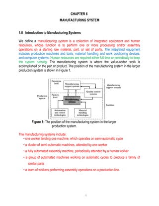
  • 1. CHAPTER 6 MANUFACTURING SYSTEM 1.0 Introduction to Manufacturing Systems We define a manufacturing system is a collection of integrated equipment and human resources, whose function is to perform one or more processing and/or assembly operations on a starting raw material, part, or set of parts. The integrated equipment includes production machines and tools, material handling and work positioning devices, and computer systems. Human resources are required either full time or periodically to keep the system running. The manufacturing system is where the value-added work is accomplished on the part or product. The position of the manufacturing system in the larger production system is shown in Figure 1. Figure 1: The position of the manufacturing system in the larger production system. The manufacturing systems include: • one worker tending one machine, which operates on semi-automatic cycle • a cluster of semi-automatic machines, attended by one worker • a fully automated assembly machine, periodically attended by a human worker • a group of automated machines working on automatic cycles to produce a family of similar parts • a team of workers performing assembly operations on a production line. 1
  • 2. In the present chapter, we classify these manufacturing systems and examine their features and performance. In other chapters in this part of the book, we discuss the various manufacturing systems of greatest commercial and technological importance 1.1 COMPONENTS OF A MANUFACTURING SYSTEM A manufacturing system consists of several components. In a given system, these components usually include: • production machines plus tools, fixtures, and other related hardware • material handling system • computer systems to coordinate and/or control the above components • human workers 1.1.1 Production Machines In virtually all modern manufacturing systems, most of the actual processing or assembly work is accomplished by machines or with the aid of tools. The machines can be classified as: (1) manually operated, (2) semi-automated, or (3) fully automated. Manually operated machines are directed or supervised by a human worker. The machine provides the power for the operation and the worker provides the control. Conventional machine tools (e.g., lathes, milling machines, drill presses) fit into this category. The worker must be at the machine continuously. A semi-automated machine performs a portion of the work cycle under some form of program control, and a human worker tends to the machine for the remainder of the cycle, by loading and unloading it or performing some other task each cycle. An example of this category is a CNC lathe controlled for most of the work cycle by the part program, but requiring a worker to unload the finished part and load the next workpiece at the end of the part program. In these cases, the 2
  • 3. worker must attend to the machine every cycle, but continuous presence during the cycle is not always required. If the automatic machine cycle takes, say, 10 min, while the part unloading and loading portion of the work cycle only takes 1 min, then there may be an opportunity for one worker to tend more than one machine. A fully automated machine is its capacity to operate for extended periods of time with no human attention. By extended periods of time, we generally mean longer than one work cycle. A worker is not required to be present during each cycle. Instead, the worker may need to tend the machine every tenth cycle or every hundredth cycle. An example of this type of operation is found in many injection molding plants, where the molding machines run on automatic cycle, but periodically the collection bin full of molded parts at the machine must be taken away and replaced by an empty bin. 1.1.2 Material Handling System In most processing and assembly operations performed on discrete parts and products, the following ancillary functions must be provided: (1) loading and unloading work units (2) positioning - the work units at each station. (3) transporting These functions are accomplished by the material handling system. Most material handling systems used in production also provide (4) a temporary storage function. The purpose of storage in these systems is usually to make sure that work is always present for the stations, that is, that the stations are not starved (meaning that they have nothing to work on). 1.1.3 Computer Control System In today's automated manufacturing systems, a computer is required to control the automated and semi-automated equipment and to participate in the overall coordination and management of the manufacturing system. Even in manually driven manufacturing systems, such as a completely manual assembly line, a computer system is useful to support production. Typical computer system functions include the following: 3
  • 4. • Communicate instructions to workers. In manually operated workstations that perform different tasks on different work units, processing or assembly instructions for the specific work unit must be communicated to the operator. • Download part programs to computer-controlled machines (e.g., CNC machine tools). • Material handling system control. This function is concerned with controlling the material handling system and coordinating its activities with those of the workstations. • Schedule production. Certain production scheduling functions are accomplished at the site of the manufacturing system. • Failure diagnosis. This involves diagnosing equipment malfunctions, preparing preventive maintenance schedules, and maintaining spare parts inventory. • Safety Monitoring. This function ensures that the system does not operate in an unsafe condition. The goal of safety monitoring is to protect both the human workers manning the system and the equipment comprising the system. • Quality Control. The purpose of this control function is to detect and possibly reject defective work units produced by the system. • Operations management. Managing the overall operations of the manufacturing system, either directly (by supervisory computer control) or indirectly (by preparing the necessary reports for management personnel). 1.1.4 Human Resources 4
  • 5. In many manufacturing systems, humans perform some or all of the value-added work that is accomplished on the parts or products. In these cases, the human workers are referred to as direct labor. Through their physical labor, they directly add to the value of the work unit by performing manual work on it or by controlling the machines that perform the work. In manufacturing systems that are fully automated, direct labor is still needed to perform such activities as loading and unloading parts to and from the system, changing tools, resharpening tools, and similar functions. Human workers are also needed for automated manufacturing systems to manage or support the system as computer programmers, computer operators, part programmers for CNC machine tools , maintenance and repair personnel, and similar indirect labor tasks.. 1.2 CLASSIFICATION OF MANUFACTURING SYSTEMS There are the variety of manufacturing system types and develop a classification based on factors. The factors are: (1) types of operations performed, (2) number of workstations and system layout, (3) level of automation, (4) part or product variety. The four factors in manufacturing systems classification scheme are defined in Table 2. TABLE 2: Factors in Manufacturing Systems Classification Scheme 1.2.1 Types of Operations Performed 5
  • 6. Manufacturing systems are distinguished by the types of operations they perform such as (1) processing operations on individual work units (2) assembly operations to combine individual parts into assembled entities. 1.2.2 Number of Workstations and System Layout The number of workstations is a key factor in the classification scheme. It exerts a strong influence on the performance of the manufacturing system in terms of production capacity, productivity, cost per unit, and maintainability. More stations mean that the system is more complex and therefore more difficult to manage and maintain. The system consists of more workers, more machines, and more parts being handled. The logistics and coordination of the system becomes more involved. Maintenance problems occur more frequently. Closely related to number of workstations is the arrangement of the workstations, that is, the way the stations are laid out. This, of course, applies mainly to systems with multiple stations. The classification scheme is applicable to manufacturing systems that perform either processing or assembly operations. Although these operations are different, the manufacturing systems to perform them possess similar configurations. According to number of stations and the layout of the stations, the classification scheme has three levels: Type I Single station. This is the simplest case, consisting of one workstation (n = 1), usually including a production machine that can be manually operated, semi automated, or fully automated. Type II Multiple stations with variable routing. This manufacturing system consists of two or more stations (n > 1) that are designed and arranged to accommodate the processing or assembly of different part or product styles. Type III Multiple stations with fixed routing. 6
  • 7. This system has two or more workstations (n > 1), which are laid out as a production line. 1.2.3 Level of Automation The level of automation is another factor that characterizes the Manufacturing system. As defined above, the workstations (machines) in a manufacturing system can be manually operated, semi-automated, or fully automated. 1.2.4 Part or Product Variety A fourth factor that characterizes a manufacturing system is the degree to which it is capable of dealing with variations in the parts or products it produces. Examples of possible variations that a manufacturing system may have to cope with include: • variations in type and/or color of plastic of molded parts in injection molding • variations in electronic components placed on a standard size printed circuit board • variations in the size of printed circuit boards handled by a component placement machine • variations in geometry of machined parts • variations in parts and options in an assembled product on a final assembly line. 2.0 FLEXIBLE MANUFACTURING SYSTEMS WHAT IS AN FMS? Flexible Manufacturing System (FMS) is a highly automated GT machine cell, consist- ing of a group of processing workstations (usually CNC machine tools), interconnected by an automated material handling and storage system, and controlled by a distributed computer system. The FMS is most suited for the mid-variety, mid-volume production range (refer to type of flexible automation). The initials FMS are sometimes used to denote the term flexible machining system. 7
  • 8. The machining process is presently the largest application area for FMS technology. However, it seems appropriate to interpret FMS in its broader meaning, allowing for a wide range of possible applications beyond machining. An FMS relies on the principles of group technology. No manufacturing system can be completely flexible. There are limits to the range of parts or products that can be made in an FMS. What Makes It Flexible? There are three identified capabilities that a manufacturing system must possess to be flexible: i. the ability to identify and distinguish among the different part or product styles processed by the system, ii. quick changeover of operating instructions, and iii. quick changeover of physical setup. Flexibility is an attribute that applies to both manual and automated systems. In manual systems, the human workers are often the enablers of the system's flexibility. To develop the concept of flexibility in an automated manufacturing system, consider a machine cell consisting of two CNC machine tools that are loaded and unloaded by an industrial robot from a parts carousel. 8
  • 9. The cell operates unattended for extended periods of time. Periodically, a worker unload completed parts from the carousel and replace them with new workparts. By definition, this is an automated manufacturing cell, but is it a flexible manufacturing cell? One might argue that yes, it is flexible, since the cell consists of CNC machine tools, and CNC machines are flexible because they can be programmed to machine different part configurations. However, if the cell only operates in a batch mode, in which the same part style is produced by both machines in lots of several dozen (or several hundred) units, then this does not qualify as flexible manufacturing. To qualify as being flexible, a manufacturing system should satisfy several criteria. The following are four reasonable tests of flexibility in an automated manufacturing system: i. Part variety test. Can the system process different part styles in a non-batch mode? ii. Schedule change test. Can the system readily accept changes in production schedule, and changes in either part mix or production quantities? iii. Error recovery test. Can the system recover gracefully from equipment malfunctions and breakdowns, so that production is not completely disrupted? iv. New part test. Can new part designs be introduced into the existing product mix with relative ease? 9
  • 10. If the answer to all of these questions is "yes" for a given manufacturing system, then the system can be considered flexible. If the automated system does not meet at least the first three tests, it should not be classified as an FMS. Types of FMS Types of Flexibility in Manufacturing Comparison of four criteria of flexibility in a Manufacturing System and the seven types of flexibility. 10
  • 11. FMS can be distinguished according to the kinds of operations such as: i. processing operations ii. assembly operation FMS can be classified into two: i. number of machines ii. level of flexibility Number of Machines i. Typical categories: A Single Machine Cell (SMC) Consists of one CNC machining center combined with a parts storage system for unattended operation. Completed parts are periodically unloaded from the parts storage unit, and raw workparts are loaded into it. The cell can be designed to operate in either a batch mode or a flexible mode or in combinations of the two. When operated in a batch mode, the machine processes parts of a single style in specified lot sizes and is then changed over to process a batch of the next part style. When operated in a flexible mode, the system satisfies three of the four flexibility tests: 11
  • 12. (1) processing different part styles, (2) responding to changes in production schedule, and (4) accepting new part introductions. Criterion (3), error recovery, cannot be satisfied because if the single machine breaks down, production stops. A Single Machine Cell – Consists of one machining CNC center and part storage unit A Flexible Manufacturing Cell (FMC) Consists of two or three processing workstations (typically CNC machining centers or turning centers) plus a part handling system. The part handling system is connected to a load/unload station. In addition, the handling system usually includes a limited parts storage capacity. A flexible manufacturing cell satisfies the four flexibility tests. 12
  • 13. A Flexible Manufacturing Cell – Consists of three identical processing stations ( CNC, Load/Unload station and part handling system) A Flexible Manufacturing System (FMS) Has four or more processing workstations connected mechanically by a common part handling system and electronically by a distributed computer system. The different between an FMS and an FMC: i. the number of machines: an FMC has two or three machines, while an FMS has four or more. ii. the FMS generally includes non-processing workstations that support production but do not directly participate in it. These other stations include part/pallet washing stations, coordinate measuring machines, and so on. iii. the computer control system of an FMS is generally larger and more so- phisticated, often including functions not always found in a cell, such as diagnostics and tool monitoring. These additional functions are needed more in an FMS than in an FMC because the FMS is more complex. The characteristics of the three categories of flexible manufacturing cells and systems are summarized: 13
  • 14. Features of the three categories of the flexible cells and system Flexibility Criteria Applied to the Three Types of Manufacturing Cells and System Level of Flexibility. Another classification of FMS is according to the level of flexibility designed into the system. This method of classification can be applied to systems with any number of workstations, but its application seems most common with FMCs and FMSs i. dedicated FMS ii. random-order FMS A dedicated FMS is designed to produce a limited variety of part styles, and the com- plete universe of parts to be made on the system is known in advance. The part family 14
  • 15. is likely to be based on product commonality rather than geometric similarity. The product design is considered stable, and so the system can be designed with a certain amount of process specialization to make the operations more efficient. A random-order FMS is more appropriate when the part family is large, there are sub- stantial variations in part configurations, there will be new part designs introduced into the system and engineering changes in parts currently produced, and the production schedule is subject to change from day-to-day. To accommodate these variations, the random-order FMS must be more flexible than the dedicated FMS. It is equipped with general-purpose machines to deal with the variations in product and is capable of pro- cessing parts in various sequences (random-order). A more sophisticated computer control system is required for this FMS type. The dedicated FMS is less flexible but more capable of higher production rates. The random-order FMS is more flexible but at the price of lower production rates. A comparison and comparisons of the features of these two FMS types is shown as below. 15
  • 16. Comparison between dedicated and random order FMS types Flexibility Criteria Applied to Dedicated and Random Order FMS FMS COMPONENTS There are four basic components of an FMS: i. workstations ii. material handling and storage system iii. computer control system iv. workers/operators Workstations The processing or assembly equipment used in an FMS depends on the type of work accomplished by the system. In a system designed for machining operations, the principle types of processing station are CNC machine tools. However, the FMS concept is also applicable to various other processes as well. Following are the types of workstations typically found in an FMS. Load/Unload Stations. The load/unload station is the physical interface between the FMS and the rest of the factory. Raw workparts enter the system at this point, and finished parts exit the system from here. Loading and unloading can be accomplished either manually or by automated handling systems. Manual loading and unloading is prevalent in most FMSs today. The load/unload station should be ergonomically designed to permit convenient and safe movement of workparts. For parts that are too heavy to lift by the operator, 16
  • 17. mechanized cranes and other handling devices are installed to assist the operator. A certain level of cleanliness must be maintained at the workplace, and air hoses or other washing facilities are often required to flush away chips and ensure clean mounting and locating points. The station is often raised slightly above floor level using an open-grid platform to permit chips and cutting fluid to drop through the openings for subsequent recycling or disposal. The load/unload station should include a data entry unit and monitor for communi- cation between the operator and the computer system. Instructions must be given to the operator regarding which part to load onto the next pallet to adhere to the production schedule. When the part loading procedure has been completed, the han- dling system must proceed to launch the pallet into the system. Machining Stations. The most common applications of FMSs are machining operations. The workstations used in these systems are therefore predominantly CNC machine tools. Most common is the CNC machining center. CNC machining centers possess features that make them compatible with the FMS, including automatic tool changing and tool storage, use of palletized workparts, CNC, and capacity for distributed numerical control (DNC). Machining centers can be ordered with automatic pallet changers that can be readily interfaced with the FMS part handling system. Machining centers are generally used for nonrelational parts. For rotational parts, turning centers are used; and for parts that are mostly rotational but require multitooth rotational cutters (milling and drilling), mill-turn centers can be used. In some machining systems, the types of operations performed are concentrated in a certain category, such as milling or turning. For milling, special milling machine modules can be used to achieve higher production levels than a machining center is capable of. The milling module can be vertical spindle, horizontal spindle, or multiple spindle. For turning operations, special turning modules can be designed for the FMS Other Processing Stations. The FMS concept has been applied to other processing operations in addition to machining. One such application is sheet metal fabrication processes. The processing workstations consist of pressworking operations, such as punching, shearing, and certain bending and forming processes. 17
  • 18. Assembly. Some FMSs are designed to perform assembly operations. Flexible automated assembly systems are being developed to replace manual labor in the assembly of products typically made in batches. Industrial robots are often used as the automated workstations in these flexible assembly systems. Other Stations and Equipment. Inspection can be incorporated into an FMS, either by including an inspection operation at a processing workstation or by including a station specifically designed for inspection. Coordinate measuring machines, special inspection probes that can be used in a machine tool spindle, and machine vision are three possible technologies for performing inspection on an FMS. Inspection has been found to be particularly important in flexible assembly systems to ensure that components have been properly added at the workstations. Material Handling and Storage System The second major component of an FMS is its material handling and storage system. Functions of the Handling System. The material handling and storage system in an FMS performs the following functions: • Random, independent movement of work-parts between stations. This means that parts must be capable of moving from any one machine in the system to any other machine, to provide various routing alternatives for the different parts and to make machine substitutions when certain stations are busy. • Handle a variety of work-part configurations. For prismatic parts, this is usually accomplished by using modular pallet fixtures in the handling system. The fixture is located on the top face of the pallet and is designed to accommodate different part configurations by means of common components, quick-change features, and other devices that permit a rapid build-up of the fixture for a given part. The base of the pallet is designed for the material handling system. For rotational parts, industrial robots are often used to load and unload the turning machines and to move parts between stations. • Temporary storage. The number of parts in the FMS will typically exceed the 18
  • 19. number of parts actually being processed at any moment. Thus, each station has a small queue of parts waiting to be processed, which helps to increase machine utilization. • Convenient access for loading and unloading work-parts. The handling system must include locations for load/unload stations. • Compatible with computer control. The handling system must be capable of being controlled directly by the computer system to direct it to the various workstations, load/unload stations, and storage areas. Material Handling Equipment. The types of material handling systems used to transfer parts between stations in an FMS include a variety of conventional material transport equipment, in-line transfer mechanisms, and industrial robots. The material handling function in an FMS is often shared between two systems: (1) a primary handling system and (2) a secondary handling system. The primary handling system establishes the basic layout of the FMS and is responsible for moving workparts between stations in the system. The secondary handling system consists of transfer devices, automatic pallet changers, and similar mechanisms located at the workstations in the FMS. The function of the secondary handling system is to transfer work from the primary system to the machine tool or other processing station and to position the parts with sufficient accuracy and repeatability to perform the processing or assembly operation. The primary handling system is sometimes supported by an automated storage sys- tem and integrated with an automated storage/retrieval system (AS/RS), and the S/R machine serves the work handling function for the workstations as well as delivering parts to and from the storage racks. Computer Control System The FMS includes a distributed computer system that is interfaced to the 19
  • 20. workstations, material handling system, and other hardware components. A typical FMS computer system consists of a central computer and microcomputers controlling the individual machines and other components. The central computer coordinates the activities of the components to achieve smooth overall operation of the system. Functions performed by the FMS computer control system can be grouped into the following categories: 1. Workstation control. In a fully automated FMS, the individual processing or assembly stations generally operate under some form of computer control. For a machining system, CNC is used to control the individual machine tools. 2. Distribution of control instructions to workstations. Some form of central intelligence is also required to coordinate the processing at individual stations. In a machining FMS, part programs must be downloaded to machines, and DNC is used for this purpose. The DNC system stores the programs, allows submission of new programs and editing of existing programs as needed, and performs other DNC functions. 3. Production control. The part mix and rate at which the various parts are launched into the system must be managed. Input data required for production control includes desired daily production rates per part, numbers of raw workparts available, and number of applicable pallets. The production control function is accomplished by routing an applicable pallet to the load/unload area and providing instructions to the operator for loading the desired workpart. 4. Traffic control. This refers to the management of the primary material handling system that moves workparts between stations. Traffic control is accomplished by actuating switches at branches and merging points, stopping parts at machine tool transfer locations, and moving pallets to load/unload stations. 5. Shuttle control. This control function is concerned with the operation and control of the secondary handling system at each workstation. Each shuttle must be coordinated with the primary handling system and synchronized with the operation of the machine tool it serves. 6. Workpiece monitoring. The computer must monitor the status of each cart and/or pallet in the primary 20
  • 21. and secondary handling systems as well as the status of each of the various workpiece types. 7. Tool control. In a machining system, cutting tools are required. Tool control is concerned with managing two aspects of the cutting tools: • Tool location. This involves keeping track of the cutting tools at each workstation. If one or more tools required to process a particular workpiece is not present at the station that is specified in the part's routing, the tool control subsystem takes one or both of the following actions: (a) determines whether an alternative workstation that has the required tool is available and/or (b) notifies the operator responsible for tooling in the system that the tool storage unit at the station must be loaded with the required cutter(s). • Tool life monitoring. In this aspect of tool control, a tool life is specified to the computer for each cutting tool in the FMS. A record of the machining time usage is maintained for each of the tools, and when the cumulative machining time reaches the specified life of the tool, the operator is notified that a tool replacement is needed. 8. Performance monitoring and reporting. The computer control system is programmed to collect data on the operation and performance of the FMS. This data is periodically summarized, and reports are prepared for management on system performance. 9. Diagnostics. This function is available to a greater or lesser degree on many manufacturing systems to indicate the probable source of the problem when a malfunction occurs. It can also be used to plan preventive maintenance in the system and to identify impending failures. The purpose of the diagnostics function is to reduce breakdowns and downtime and increase availability of the system. Human Resources One additional component in the FMS is human labor. Humans are needed to manage the operations of the FMS. Functions typically performed by humans include: 21
  • 22. (1) loading raw workparts into the system, (2) unloading finished parts (or assemblies) from the system, (3) changing and setting tools, (4) equipment maintenance and repair, (5) NC part programming in a machining system, (6) programming and operating the computer system, and (7) overall management of the system. FMS benefits A number of benefits can be expected in successful FMS applications. The principal benefits are the following: • Increased machine utilization. FMSs achieve a higher average utilization than machines in a conventional batch production machine shop. Reasons for this include: 24 hr/day operation, automatic tool changing at machine tools, automatic pallet changing at workstations, queues of parts at stations, and dynamic scheduling of production that takes into account irregularities from normal operations. It should be possible to approach 80-90% asset utilization by implementing FMS technology • Fewer machines required. Because of higher machine utilization, fewer machines are required. • Reduction in factory floor space required. Compared with a job shop of equivalent capacity, an FMS generally requires less floor area. Reductions in floor space requirements are estimated to be 40-50% • Greater responsiveness to change. An FMS improves response capability to part design changes, introduction of new parts, changes in production schedule and product mix, machine breakdowns, and cutting tool failures. Adjustments can be made in the production schedule from one day to the next to respond to rush orders and special customer requests. 22
  • 23. • Reduced inventory requirements. Because different parts are processed together rather than separately in batches, work-in-process (WIP) is less than in a batch production mode. The inventory of starting and finished parts can be reduced as well. Inventory reductions of 60-80% are estimated. • Lower manufacturing lead times. Closely correlated with reduced WIP is the time spent in process by the parts. This means faster customer deliveries. • Reduced direct labor requirements and higher labor productivity. Higher production rates and lower reliance on direct labor translate to greater productivity per labor hour with an FMS than with conventional production methods. Labor savings of 30-50% are estimated. • Opportunity for unattended production. The high level of automation in an FMS allows it to operate for extended periods of time without human attention. In the most optimistic scenario, parts and tools are loaded into the system at the end of the day shift, and the FMS continues to operate throughout the night so that the finished parts can be unloaded the next morning. MANUAL ASSEMBLY SYSTEM A Manual Assembly Line is a production line that consists of a sequence of workstations where assembly tasks are performed by human workers. Products are assembled as they move along the line. A mechanized material transport system is typically used to move the base part along the line as it is gradually transformed into the final product. However, in some manual lines, the product is simply moved manually from station-to-station. The production rate of an assembly line is determined by its slowest station. Stations capable of working faster are ultimately limited by the slowest station. 23
  • 24. Products Usually Made on Manual Assembly Lines Typical assembly operations performed at stations on a manual assembly line Assembly Workstations A workstation on a manual assembly line is a designated location along the work flow path at which one or more work elements are performed by one or more workers. The work elements represent small portions of the total work that must be accomplished to assemble the product. Some workstations are designed for workers to stand, while others allow the workers to sit. When the workers stand, they can move about the station area to perform their assigned task. This is common for assembly of large products, such as cars, trucks, and major appliances. The typical case is when the product is moved by a conveyor at constant velocity through the station. The worker begins the assembly 24
  • 25. task near the upstream side of the station and moves along with the work unit until the task is completed, then walks back to the Reasons for Manual Assembly • Specialization of labor. This principle asserts that when a large job is divided into small tasks and each task is assigned to one worker, the worker becomes highly proficient at performing the single task. Each worker becomes a specialist. One of the major explanations of specialization of labor is the learning curve*. • Interchangeable parts in which each component is manufactured to sufficiently close tolerances that any part of a certain type can be selected for assembly with its mating component. Without inter-changeable parts, assembly would require filing and fitting of mating components, rendering assembly line methods impractical. • Work principle in material handling, which provides that each work unit flows smoothly through the production line, traveling minimum distances between stations. Principle 3. work principle: Material handling work should be minimized without sacrificing productivity or the level of service required of the operation. • The measure of material handling work is flow rate (volume, weight, or count per unit of time) multiplied by distance moved. • Consider each pickup and set-down, or placing material in and out of storage, as distinct moves and components of the distance moved. • Simplifying processes by reducing, combining, shortening, or eliminating unnecessary moves will reduce work. • Where possible, gravity should be used to move materials or to assist in their movement while respecting consideration of safety and the potential for product damage. • The Work Principle applies universally, from mechanized material handling in a factory to over-the-road trucking. 25
  • 26. • The Work Principle is implemented best by appropriate layout planning: locating the production equipment into a physical arrangement corresponding to the flow of work. This arrangement tends to minimize the distances that must be traveled by the materials being processed. • Line pacing. Workers on an assembly line are usually required to complete their assigned tasks on each product unit within a certain cycle time, which paces the line to maintain a specified production rate. Pacing is generally implemented by means of a mechanized conveyor. * Learning curve Is a phenomenon virtually occurs in all manufacturing system. It applies to any repetitive activity. It is happened when the cycle time required to perform a given activity decreases as the number of cycles increases. The learning curve phenomenon According to learning curve theory, there is a constant learning rate that applies to a given task. Different learning rates are associated with different types of tasks. And different workers have different learning capabilities that affect the learning rate. Whatever the learning rate, its effect is most identifiable every time the number of units doubles. Assuming a learning rate of 80%, the time to produce the second unit is 80% of that for the first unit the time to produce the fourth unit is 80% of that for the second; and so forth. Every time the number of units doubles, the task time per unit has been reduced to 80% of its previous value. Between 26
  • 27. these points, the unit task times gradually decrease. We can calculate the expected time for the Nth work unit by means of the following equation: TN = T1(N)m where TN = task time for the Nth unit of work; T1 = task time for the first work unit N = the number of the unit produced in the series; and m = an exponent that depends or the learning rate. The value of m can be determined as follows: m = ln(LR) ln (2 ) where LR = learning rate, expressed as a decimal fraction, such as 0.80. The natural logarithm of 2 in the denominator manifests the doubling effect of the learning rate. This causes the curve to plot as a straight line in a log-log graph. EXAMPLE A certain mechanical assembly task required 3.75 min to complete when a skilled worker did it for the first time. The task will be performed on an assembly line used to produce 1000 units of a particular product. The line is currently operating on a pilot basis, while workers are learning their respective tasks. The line will run on this basis for 50 units, after which it will go into regular production. a) If the learning rate for tasks of this type is 84%, what will the task time be for the 50th unit b) For the 1000th unit? Solution: a) to determine the task time for any numbered unit, we need to compute the exponent m, m = ln (0.84) = -0.2515 ln (2) 27
  • 28. The task time for the 50th unit is, T50 = 3.75(50) –0.2515 = 3.75(0.3738) = 1.402 min b) The task time for the 1000th unit T1000 = 3.75(1000) –0.2515 = 0.660 min AUTOMATED MANUFACTURING SYSTEMS Automated Production Lines require a significant capital investment. It is an example of fixed automation, where it is difficult to alter the sequence and content of the processing operations. The application is appropriate under the conditions: i. High product demand ii. Stable product design iii. Long product life iv. Multiple operations The benefits of Automated Production Lines: i. low direct labour content ii. low product cost iii. production lead time reduced/minimized iv. factory floor space minimized Fundamentals of Automated Production Lines (APL) APL consists of multiple workstation that are linked together by a work handling system that transfers parts from one station to other station. 28
  • 29. Each station performs a different operation, so that the sum total of of all operations is required to complete one unit of work. 29