1. Workshop 8
Structured Hex Meshing: Pipe Creep Model
You need to consider the type of element that will be used before you start building the
mesh for a particular problem. A suitable mesh design that uses quadratic elements may
very well be unsuitable if you change to linear, reduced-integration elements. For this
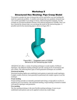
example use 20-node hexahedral elements with reduced integration (C3D20R). Once you
have selected the element type, you can design the mesh for the intersecting pipes. A
possible mesh for the intersecting pipes is shown in Figure W8–1.
Figure W8–1. Suggested mesh of C3D20R
elements for the intersecting pipe model
ABAQUS/CAE offers a variety of meshing techniques to mesh models of different
topologies. The different meshing techniques provide varying levels of automation and
user control. The following three types of mesh generation techniques are available:
Structured meshing
Structured meshing applies pre-established mesh patterns to particular model topologies.
Complex models, however, must generally be partitioned into simpler regions to use this
technique.
Swept meshing
Swept meshing extrudes an internally generated mesh along a sweep path or revolves it
around an axis of revolution. Like structured meshing, swept meshing is limited to models
with specific topologies and geometries.
Free meshing
The free meshing technique is the most flexible meshing technique. It uses no pre-
established mesh patterns and can be applied to almost any model shape.
2. When you enter the Mesh module, ABAQUS/CAE color codes regions of the model
according to the methods it will use to generate a mesh:
· Green indicates that a region can be meshed using structured methods.
· Yellow indicates that a region can be meshed using sweep methods.
· Pink indicates that a region can be meshed using the free method.
· Orange indicates that a region cannot be meshed using the default element shape
assignment and must be partitioned further.
In this problem you will create a structured mesh. You will find that the model must first
be partitioned further to use this mesh technique. After the partitions have been created, a
global part seed will be assigned and the mesh will be created.
To begin this workshop, start a new session of ABAQUS/CAE from the
workshops/pipeCreep directory. Open the database containing the pipe creep
model.
To partition the pipe model:
1. From the Module list located under the toolbar, select Mesh to enter the Mesh
module.
The part is colored orange initially, indicating that with the default set of mesh controls, a
hexahedral mesh cannot be created. Cell partitions are required to permit structured
meshing.
2. Partition the pressure vessel in half as shown in Figure W8–2:
A. From the main menu bar, select ToolsPartition to open the Create
Partition dialog box.
B. In this dialog box, select Cell as the type and Define cutting plane as the
method.
C. Click OK.
D. In the prompt area, choose the Point & Normal technique to define the
cutting plane. Choose the point indicated in Figure W8–2 as the point through
which the cutting plane will pass and any vertical edge of the pipe as the
normal to the plane.
The bottom half of the vessel turns green, indicating it is structured meshable.
W8.2
3. Figure W8–2. Cell partition
The region containing the pipe intersection will be partitioned using a combination of face
and cell partitions. These partitions are described next.
3. Partition the faces of the pipes on the symmetry planes as follows:
A. From the main menu bar, select ToolsPartition to open the Create
Partition dialog box.
E. In this dialog box, select Face as the type and Sketch as the method.
F. Click OK.
G. Select the face shown in Figure W8–3 as the face to be partitioned.
H. Choose the edge shown in Figure W8–3 as the edge that will appear vertical
and on the right side of the sketch.
I. From the main menu bar, select AddConstruction to define two Vertical
and two Horizontal construction lines, as indicated in Figure W8–4.
J. Use the Create Lines: Connected tool to define two sketch lines as
indicated in Figure W8–4.
K. Repeat steps A through G for the symmetry face shown in Figure W8–5.
Create the construction geometry and sketch lines indicated in Figure W8–6.
The partitioned symmetry faces appear as shown in Figure W8–7.
Point through which cutting
plane passes
Normal to the
cutting plane
W8.3
4. Figure W8–3. First face partition
Figure W8–4. Construction geometry for first face partition
Partition this face
Edge that will appear vertical
and on the right of the sketch
Horizontal construction line
through vertex A
A
B
Vertical construction line
through vertex B
Additional horizontal
and vertical
construction lines
W8.4
Sketch lines; use intersections of
construction lines as snap points
5. Figure W8–5. Second face partition
Figure W8–6. Construction geometry for second face partition
W8.5
C
Horizontal and vertical
construction lines through
vertex C
Additional vertical
construction line
Horizontal sketch line
from vertex C to the
intersection of the
construction lines
Skewed sketch line from vertex D to
the intersection between
construction line and curved edge of
part
D
Partition this face
Edge that will appear vertical and
on the right of the sketch
6. Figure W8–7. Partitioned symmetry faces
4. Partition the inner surface of the pressure vessel using a curved path between two
edges:
A. From the main menu bar, select ToolsPartition to open the Create
Partition dialog box.
L. In this dialog box, select Face as the type and Curved path normal to 2
edges as the method.
M. Click OK.
N. Select the face shown in Figure W8–8 as the face to be partitioned.
O. In the prompt area, choose Pick as the method by which to select the edge
points.
P. Select the edges and points indicated in Figure W8–9 to define the partition.
The partitioned face appears as shown in Figure W8–10.
W8.6
7. Figure W8–8. Inner surface of pressure vessel
Figure W8–9. Edges and points used to define partition
W8.7
edge
point
edge
point
8. Figure W8–10. Partitioned inner face
5. Finally, partition the cells of the pipe using the n-sided patch technique:
A. From the main menu bar, select ToolsPartition to open the Create
Partition dialog box.
Q. In this dialog box, select Cell as the type and N-sided patch as the method.
R. Click OK.
S. Select the top half of the pipe as the region to be partitioned. In the prompt
area, click Select Corner Points as the method by which to specify the
patch. Use 4 corner points to define the patch.
T. Select the points indicated in Figure W8–11 as the points defining the patch,
and create the partition. Be sure to select the points in the order indicated in
the figure.
The top portion of the pipe is now colored green.
U. Repeat the above steps to partition the center cell of the model using the points
indicated in Figure W8–12 as the points defining the 4-sided patch.
6. After you have partitioned the part, all part regions should be colored green, as
shown in Figure W8–13. This indicates structured hexahedral element meshing
will be used everywhere.
W8.8
9. Figure W8–11. First 4-sided patch
Figure W8–12. Second 4-sided patch
W8.9
Point 1
Point 2
Point 3
Point 4
Point 3
Point 4
Point 1
Point 2
10. Figure W8–13. Partitioned geometry
To assign a global part seed and create the mesh:
1. From the main menu bar, select SeedInstance; specify a target global element
size of 0.027. Seeds appear on all the edges.
7. From the main menu bar, select MeshElement Type to choose the element
type for the part. Because of the partitions you have created, the part is now
composed of several regions.
A. Use the cursor to draw a box around the entire part and, thus, select all regions
of the part. Click Done in the prompt area.
V. In the Element Type dialog box that appears, select the Standard element
library, 3D Stress family, Quadratic geometric order, and Hex, Reduced
integration element. Click OK to accept the choice of C3D20R as the
element type.
8. From the main menu bar, select MeshInstance. Click Yes in the prompt area
to mesh the part instance. The resulting mesh is shown in Figure W8–1.
9. Save your model database, and exit your ABAQUS/CAE session.
W8.10