SlideShare uma empresa Scribd logo
1 de 11
Baixar para ler offline
Workshop 3
Importing and Editing an Orphan Mesh:
Pump Model
Introduction
The structural response of the pump assembly shown in Figure W3–1 will be determined.
The assembly components include the pump housing (imported as an orphan mesh), a
gasket, a cover, and eight bolts (all imported as CAD geometry). The analysis involves
application of pre-tensioning loads in the bolts followed by internal pressure.
Figure W3–1. Pump assembly
In this workshop, you will create the parts of the model. Use the Part module of
ABAQUS/CAE to import the mesh of a pump housing. Some modifications of its
geometric features follow. The other components of the pump assembly (cover, gasket,
and bolts) will be imported as CAD geometry. All of the parts will be halved to take
advantage of symmetry.
Note: The parts created in this workshop will be used in subsequent workshops to build
the complete model and to perform the analysis. It is important that you use the
dimensions stated and not deviate from the workshop instructions; otherwise, you may
find it difficult to complete the subsequent workshops.
Orphan mesh import
Follow the steps below to import the mesh of the pump housing model.
1. Start a new session of ABAQUS/CAE from workshops/pump directory.
2. Switch to the Part module (optional).
3. From the main menu bar, select FileImportModel. From the list of
available models, select pump_ribs.inp.
pump housing
gasket
cover
bolts
4. ABAQUS/CAE takes a few seconds to import the model. Once the model is
imported, you will be in the Assembly module. Switch back to the Part module.
Notice a new model (named pump_ribs) that contains the imported part (named
PUMP–1) has been created. The model appears as shown in Figure W3–2.
Figure W3–2. Orphan mesh of pump housing
Editing nodal coordinates
Your first task will be to change the inner diameter of the hole that goes through the top
of the pump. The coordinates of the nodes along the inner diameter need to be changed.
Since these nodes lie on a circular surface, it will be advantageous to define a cylindrical
coordinate system and simply change the radial coordinate of the nodes. Follow the steps
below to achieve this task.
1. From the main menu bar, select ViewViews Toolbox. In the Views dialog
box, select the 1–2 view. Turn off the perspective view by clicking the Turn
Perspective Off tool ( ) and zoom into the component so that the hole is
clearly visible (see Figure W3–3).
Figure W3–3. Top view of pump housing
5. From the main menu bar, select ToolsDatum. The Create Datum dialog box
appears (see Figure W3–4). Select CSYS as the datum type. Select the 3 points
method, and click OK. When prompted for the type of coordinate system, choose
W3.2
Cylindrical. Place the coordinate system at the origin (0.0, 0.0, 0.0) and click
Create Datum.
A cylindrical datum coordinate system is created. The origin of the coordinate
system coincides with the position of the center of the hole.
Figure W3–4. Create Datum dialog box
6. You will now modify the inner diameter of the hole. From the main menu bar,
select PartMesh Tools. In the Mesh Tools dialog box, select Node as the
category and Edit as the method, as shown in Figure W3–5. Click OK to close
the dialog box and proceed.
Figure W3–5. Mesh Tools dialog box
7. You will be prompted to select the nodes to be modified. Begin by setting the
selection filters as shown in Figure W3–6 by clicking the Show/Hide Selection
Options tool, in the prompt area.
W3.3
Figure W3–6. Selection filters
8. The nodes can be selected in one of two ways:
· Try selecting the nodes individually (the default selection technique) using a
Circular Drag Shape. The center of the drag shape should be the center of the
cylindrical coordinate system defined earlier (see step 2). Select a perimeter point
for the drag shape such that you include all the nodes on the inside surface of the
hole. The selected nodes will be highlighted in red after the selection, as shown in
Figure W3–7. You may wish to rotate your model to check whether all the nodes
have been selected properly.
· You may also select the nodes using the face angle method (i.e., by specifying the
maximum deviation in the angle between adjacent element faces). This technique
is generally more efficient than selecting the nodes individually: all nodes that
pertain to the element faces that satisfy the face angle criterion are automatically
selected. In the prompt area, choose by face angle as the method by which the
nodes will be selected. Then click on any element face located on the inner
surface of the hole. The nodes on the inner surface are highlighted in red after the
selection. As before, rotate your model to make sure all the nodes have been
selected properly.
Once you are satisfied with the selection (using either method), click Done in the
prompt area.
Figure W3–7. Modified nodes
9. The Edit Nodes dialog box appears, as shown in Figure W3–8. This dialog box
will be used to change the diameter of the hole. Click Select in the upper right
corner of the dialog box, and choose the cylindrical coordinate system defined in
step 2 by clicking on it in the viewport when prompted to choose a local
coordinate system.
Select entities inside the
drag shape
Circular drag shape
Toggle off the selection of entities
closest to the screen
W3.4
10. Using the Coordinates specification method, change the 1–coordinate (i.e., the
radial coordinate) by selecting Specify from the pull down list and entering
0.65. Click OK to close the dialog box and then Done in the prompt area to
complete the operation.
Figure W3–8. Edit Nodes dialog box
Deleting elements
You will now remove the ribs on the pump housing and then you will remove half of the
part. Begin by removing some of the elements in the rib located near the front of the
housing, as shown in Figure W3–9. Use the 3–1 view from the Views Toolbox, and
rotate the pump to view one of the front ribs, as shown in Figure W3–9.
Figure W3–9. Rib elements
1. From the main menu bar, select PartMesh Tools. In the Mesh Tools dialog
box, select Element as the category and Delete as the method. Click OK.
11. When prompted to select the elements to be deleted, use the Show/Hide
Selection Options tool to change the drag shape to a Polygon. Select some of
the elements located near the 90 bend of the rib, as shown in Figure W3–9.
12. In the prompt area, toggle on Delete associated unreferenced nodes.
13. Zoom out and rotate the view to confirm that only elements pertaining to the ribs
have been selected. If any other elements are highlighted, deselect them using
[Control]+Click. When you are satisfied with the selection, click Done to delete
the elements and their associated nodes.
14. The remaining ribs on the pump housing can be removed by selecting them
carefully in a similar fashion. However, this can be a tedious and time-consuming
W3.5
process for large, complicated models. To facilitate the process, you may delete
selected sets.
A. From the main menu bar, select PartMesh Tools. In the Mesh Tools
dialog box, click OK to continue deleting elements.
B. In the prompt area toggle on Delete associated unreferenced nodes.
C. In the prompt area, click Sets to open the Region Selection dialog box. In
this dialog box, select the set RIBS and toggle on Highlight selections in
viewport to highlight the elements belonging to this set.
D. Click Continue to delete the remaining rib elements.
E. Click Cancel to close the dialog box.
You will now halve the pump housing. Use the 1–2 view from the Views
Toolbox to facilitate element selection.
15. From the main menu bar, select PartMesh Tools. In the Mesh Tools dialog
box, click OK to continue deleting elements.
16. In the prompt area, toggle on Delete associated unreferenced nodes.
Tip: If the Region Selection dialog box appears, click Select in Viewport on
the right side of the prompt area so you can select elements in the viewport.
17. Select the upper half of the pump housing for deletion, as shown in W3–10. When
you are satisfied with the selection, click Done to delete the elements and their
associated nodes.
The half pump housing without the ribs is shown in Figure W3–11.
18. Save the model database. Name the model database file PumpAssy.cae.
W3.6
Figure W3–10. Select half of the pump housing.
Figure W3–11. Halved pump housing without ribs
Importing CAD geometry
You will now import the remaining components of the assembly into ABAQUS/CAE.
19. From the main menu bar, select FileImportPart to open the Import Part
dialog box.
20. In this dialog box, set the file type to ACIS SAT. From the list of available files,
select cover.sat. Click Continue in the dialog box to proceed.
21. In the Create Part from ACIS File dialog box, select the Import - Repair tab
and toggle on all the available repair options. Click OK to close the dialog box
and continue.
The imported part is shown in Figure W3–12a.
22. After the part is imported, use the Geometry diagnostics part query tools
(ToolsQuery) to check for any invalid or imprecise entities.
23. Repeat steps 2 through 4 to import the part defined in file gasket.sat.
The imported part is shown in Figure W3–12b.
24. Import the part defined in file n_bolts.sat without any repair options turned
on. The imported part is shown in Figure W3–12c.
25. Review the different parts of your model. Query the important dimensions using
the Query tools and note them for future reference.
26. Save your model database as PumpAssy.cae.
W3.7
rectangular drag
shape
selected
elements
Figure W3–12. Components of pump assembly
Halving the imported geometry
You will now remove half of each of the imported parts. Begin with the cover.
1. From the Part list located under the tool bar, select cover to access the cover
geometry.
27. From the main menu bar, select ViewSpecify. Using the Viewpoint method,
enter the coordinates of the viewpoint as 0,0,-1 and the coordinates of the up
vector as 0,-1,0. Click OK to apply the view and close the dialog box.
Next, create a datum axis using the steps outlined below. This axis will be used to
orient the part in the sketch plane when creating the cut profile.
28. From the main menu bar, select ToolsDatum.
29. In the Create Datum dialog box, choose Axis as the type and Principal Axis
as the method. Click OK.
30. Choose the principal Y-Axis as the datum axis.
31. From the main menu bar, select ShapeCutExtrude.
32. Select the top surface of the cover, indicated in Figure W3–13, as the plane on
which to sketch.
W3.8
(a) cover (b) gasket
(c) bolts
Figure W3–13. Sketch plane and datum axis
33. Select the datum axis as the edge that will appear vertical and on the right of the
sketch.
34. From the main menu bar, select AddLineRectangle. Sketch a rectangle
enclosing the upper half of the cover, as shown in Figure W3–14.
Figure W3–14. Cut profile
35. Click mouse button 2 to continue, and click Done in the prompt area.
36. In the Edit Cut Extrusion dialog box, choose the end condition Through All.
The direction of extrusion is into the cover. Click OK.
The final cover geometry is shown in Figure W3–15.
Figure W3–15. Cover
W3.9
sketch plane
datum axis
cut rectangle
Similarly, halve the gasket and bolt parts.
2. From the Part list located under the tool bar, select gasket to access the gasket
geometry. Use the 1–2 view from the Views Toolbox.
37. As before, define the datum axis to orient the part. From the main menu bar,
select ToolsDatum.
38. In the Create Datum dialog box, click OK to create another Axis using the
Principal Axis method. Choose the principal Y-Axis as the datum axis.
39. From the main menu bar, select ShapeCutExtrude.
40. Select the top surface of the gasket as the plane on which to sketch, as shown in
Figure W3–16. Select the datum axis as the edge that will appear vertical and on
the right of the sketch.
41. From the main menu bar, select AddLineRectangle. Sketch a rectangle
enclosing the upper half of the gasket, as shown in Figure W3–16.
Figure W3–16. Cut profiles
42. Click mouse button 2 to continue, and click Done in the prompt area.
43. In the Edit Cut Extrusion dialog box, choose the end condition Through All.
The direction of extrusion is into the gasket. Click OK.
44. Repeat steps 12 through 19 to remove four of the bolts from the part named
n_bolts. Note that the top surface of any of the bolts to the left of the datum axis
may be used as the sketch plane for the extruded cut.
The final gasket and bolt parts are shown in Figure W3–17.
45. Save the model database as PumpAssy.cae.
W3.10
(a) gasket (b) bolts
surfaces selected as sketch planes
cut rectangle
Figure W3–17. Gasket and bolts
W3.11
(a) gasket (b) bolts

Mais conteúdo relacionado

Mais procurados

Workshop8 creep-mesh
Workshop8 creep-meshWorkshop8 creep-mesh
Workshop8 creep-meshmmd110
 
Workshop7 creep-steps
Workshop7 creep-stepsWorkshop7 creep-steps
Workshop7 creep-stepsmmd110
 
Workshop10 creep-jop
Workshop10 creep-jopWorkshop10 creep-jop
Workshop10 creep-jopmmd110
 
Workshop1 cant-beam
Workshop1 cant-beamWorkshop1 cant-beam
Workshop1 cant-beammmd110
 
Workshop4 creep-props
Workshop4 creep-propsWorkshop4 creep-props
Workshop4 creep-propsmmd110
 
Workshop9 pump-mesh
Workshop9 pump-meshWorkshop9 pump-mesh
Workshop9 pump-meshmmd110
 
Workshop5 pump-mat
Workshop5 pump-matWorkshop5 pump-mat
Workshop5 pump-matmmd110
 
Workshop11 beam-load-cases
Workshop11 beam-load-casesWorkshop11 beam-load-cases
Workshop11 beam-load-casesmmd110
 
SAP2000 Piperack Tutorial 2010.pdf
SAP2000 Piperack Tutorial 2010.pdfSAP2000 Piperack Tutorial 2010.pdf
SAP2000 Piperack Tutorial 2010.pdfsdads1
 
38620317 pro e-mechanism
38620317 pro e-mechanism38620317 pro e-mechanism
38620317 pro e-mechanismTrung Quoc Le
 
Building model-sap2000-tutorial-guide
Building model-sap2000-tutorial-guideBuilding model-sap2000-tutorial-guide
Building model-sap2000-tutorial-guideVanz Einstein
 
Sap tutorial for dynamics
Sap tutorial for dynamicsSap tutorial for dynamics
Sap tutorial for dynamicscolosimoricardo
 
Finite Element Simulation with Ansys Workbench 14
Finite Element Simulation with Ansys Workbench 14Finite Element Simulation with Ansys Workbench 14
Finite Element Simulation with Ansys Workbench 14Prem Prakash Pandey
 
02 release document_8.8
02 release document_8.802 release document_8.8
02 release document_8.8struds
 
Lecture 10: introduction to computer
Lecture 10: introduction to computerLecture 10: introduction to computer
Lecture 10: introduction to computerSultan Omar Shige
 
315925614 cadence-tutorial
315925614 cadence-tutorial315925614 cadence-tutorial
315925614 cadence-tutorialkhaalidkk
 

Mais procurados (19)

Workshop8 creep-mesh
Workshop8 creep-meshWorkshop8 creep-mesh
Workshop8 creep-mesh
 
Workshop7 creep-steps
Workshop7 creep-stepsWorkshop7 creep-steps
Workshop7 creep-steps
 
Workshop10 creep-jop
Workshop10 creep-jopWorkshop10 creep-jop
Workshop10 creep-jop
 
Workshop1 cant-beam
Workshop1 cant-beamWorkshop1 cant-beam
Workshop1 cant-beam
 
Workshop4 creep-props
Workshop4 creep-propsWorkshop4 creep-props
Workshop4 creep-props
 
Workshop9 pump-mesh
Workshop9 pump-meshWorkshop9 pump-mesh
Workshop9 pump-mesh
 
Workshop5 pump-mat
Workshop5 pump-matWorkshop5 pump-mat
Workshop5 pump-mat
 
Workshop11 beam-load-cases
Workshop11 beam-load-casesWorkshop11 beam-load-cases
Workshop11 beam-load-cases
 
SAP2000 Piperack Tutorial 2010.pdf
SAP2000 Piperack Tutorial 2010.pdfSAP2000 Piperack Tutorial 2010.pdf
SAP2000 Piperack Tutorial 2010.pdf
 
38620317 pro e-mechanism
38620317 pro e-mechanism38620317 pro e-mechanism
38620317 pro e-mechanism
 
Axis vm stepbystep
Axis vm stepbystepAxis vm stepbystep
Axis vm stepbystep
 
Building model-sap2000-tutorial-guide
Building model-sap2000-tutorial-guideBuilding model-sap2000-tutorial-guide
Building model-sap2000-tutorial-guide
 
Civil 3d workflow
Civil 3d workflowCivil 3d workflow
Civil 3d workflow
 
Sap tutorial for dynamics
Sap tutorial for dynamicsSap tutorial for dynamics
Sap tutorial for dynamics
 
Finite Element Simulation with Ansys Workbench 14
Finite Element Simulation with Ansys Workbench 14Finite Element Simulation with Ansys Workbench 14
Finite Element Simulation with Ansys Workbench 14
 
02 release document_8.8
02 release document_8.802 release document_8.8
02 release document_8.8
 
Lecture 10: introduction to computer
Lecture 10: introduction to computerLecture 10: introduction to computer
Lecture 10: introduction to computer
 
315925614 cadence-tutorial
315925614 cadence-tutorial315925614 cadence-tutorial
315925614 cadence-tutorial
 
Ig proe-wf-5.0
Ig proe-wf-5.0Ig proe-wf-5.0
Ig proe-wf-5.0
 

Destaque (17)

Quan sát và kiểm tra bảng
Quan sát và kiểm tra bảngQuan sát và kiểm tra bảng
Quan sát và kiểm tra bảng
 
Seaworld® Weekday Wanderer
Seaworld® Weekday WandererSeaworld® Weekday Wanderer
Seaworld® Weekday Wanderer
 
De1
De1De1
De1
 
Arsitektur
ArsitekturArsitektur
Arsitektur
 
Pedagogía Salesiana
Pedagogía SalesianaPedagogía Salesiana
Pedagogía Salesiana
 
De3
De3De3
De3
 
20 de12
20 de1220 de12
20 de12
 
De2
De2De2
De2
 
Americans and Rhinoplasty
Americans and RhinoplastyAmericans and Rhinoplasty
Americans and Rhinoplasty
 
De1
De1De1
De1
 
Phuongtrinhlgcbsin loigiai
Phuongtrinhlgcbsin loigiaiPhuongtrinhlgcbsin loigiai
Phuongtrinhlgcbsin loigiai
 
Java printing
Java printingJava printing
Java printing
 
De2
De2De2
De2
 
Vd
VdVd
Vd
 
Lop10
Lop10Lop10
Lop10
 
Cong
CongCong
Cong
 
Partikel Materi
Partikel MateriPartikel Materi
Partikel Materi
 

Semelhante a Workshop3 pump-geo

Semelhante a Workshop3 pump-geo (20)

Ig proe-wf-5.0
Ig proe-wf-5.0Ig proe-wf-5.0
Ig proe-wf-5.0
 
Lesson02
Lesson02Lesson02
Lesson02
 
lecture_slides_esteem2019-231.pdf
lecture_slides_esteem2019-231.pdflecture_slides_esteem2019-231.pdf
lecture_slides_esteem2019-231.pdf
 
Molds design in solid works
Molds design in solid worksMolds design in solid works
Molds design in solid works
 
Introductory tutorial etab2016
Introductory tutorial etab2016Introductory tutorial etab2016
Introductory tutorial etab2016
 
Tutorial ic design
Tutorial ic designTutorial ic design
Tutorial ic design
 
Hv 4000 querying results
Hv 4000 querying resultsHv 4000 querying results
Hv 4000 querying results
 
Safe tutorial
Safe tutorialSafe tutorial
Safe tutorial
 
4. safe tutorial v. 12 ingles
4.  safe tutorial v. 12 ingles4.  safe tutorial v. 12 ingles
4. safe tutorial v. 12 ingles
 
4. safe tutorial v. 12 ingles
4.  safe tutorial v. 12 ingles4.  safe tutorial v. 12 ingles
4. safe tutorial v. 12 ingles
 
Visi progress
Visi progressVisi progress
Visi progress
 
Knowledgeware
KnowledgewareKnowledgeware
Knowledgeware
 
Cnc tutorial mastercam
Cnc tutorial mastercamCnc tutorial mastercam
Cnc tutorial mastercam
 
Xelerate mold project
Xelerate mold projectXelerate mold project
Xelerate mold project
 
Introduction to CATIA (KEY) - CAD/CAM
Introduction to CATIA (KEY) - CAD/CAMIntroduction to CATIA (KEY) - CAD/CAM
Introduction to CATIA (KEY) - CAD/CAM
 
StaadPro Manual by yousuf dinar
StaadPro Manual by yousuf dinarStaadPro Manual by yousuf dinar
StaadPro Manual by yousuf dinar
 
CIM and automation laboratory manual
CIM and automation laboratory manualCIM and automation laboratory manual
CIM and automation laboratory manual
 
IRJET- Modelling and Analysis of Two Wheeler Suspension System
IRJET- Modelling and Analysis of Two Wheeler Suspension SystemIRJET- Modelling and Analysis of Two Wheeler Suspension System
IRJET- Modelling and Analysis of Two Wheeler Suspension System
 
Dipole
DipoleDipole
Dipole
 
Executing tools-in-modelbuilder-tutorial
Executing tools-in-modelbuilder-tutorialExecuting tools-in-modelbuilder-tutorial
Executing tools-in-modelbuilder-tutorial
 

Último

Automating Google Workspace (GWS) & more with Apps Script
Automating Google Workspace (GWS) & more with Apps ScriptAutomating Google Workspace (GWS) & more with Apps Script
Automating Google Workspace (GWS) & more with Apps Scriptwesley chun
 
How to Troubleshoot Apps for the Modern Connected Worker
How to Troubleshoot Apps for the Modern Connected WorkerHow to Troubleshoot Apps for the Modern Connected Worker
How to Troubleshoot Apps for the Modern Connected WorkerThousandEyes
 
Strategies for Unlocking Knowledge Management in Microsoft 365 in the Copilot...
Strategies for Unlocking Knowledge Management in Microsoft 365 in the Copilot...Strategies for Unlocking Knowledge Management in Microsoft 365 in the Copilot...
Strategies for Unlocking Knowledge Management in Microsoft 365 in the Copilot...Drew Madelung
 
Strategies for Landing an Oracle DBA Job as a Fresher
Strategies for Landing an Oracle DBA Job as a FresherStrategies for Landing an Oracle DBA Job as a Fresher
Strategies for Landing an Oracle DBA Job as a FresherRemote DBA Services
 
From Event to Action: Accelerate Your Decision Making with Real-Time Automation
From Event to Action: Accelerate Your Decision Making with Real-Time AutomationFrom Event to Action: Accelerate Your Decision Making with Real-Time Automation
From Event to Action: Accelerate Your Decision Making with Real-Time AutomationSafe Software
 
Exploring the Future Potential of AI-Enabled Smartphone Processors
Exploring the Future Potential of AI-Enabled Smartphone ProcessorsExploring the Future Potential of AI-Enabled Smartphone Processors
Exploring the Future Potential of AI-Enabled Smartphone Processorsdebabhi2
 
[2024]Digital Global Overview Report 2024 Meltwater.pdf
[2024]Digital Global Overview Report 2024 Meltwater.pdf[2024]Digital Global Overview Report 2024 Meltwater.pdf
[2024]Digital Global Overview Report 2024 Meltwater.pdfhans926745
 
Tech Trends Report 2024 Future Today Institute.pdf
Tech Trends Report 2024 Future Today Institute.pdfTech Trends Report 2024 Future Today Institute.pdf
Tech Trends Report 2024 Future Today Institute.pdfhans926745
 
Artificial Intelligence: Facts and Myths
Artificial Intelligence: Facts and MythsArtificial Intelligence: Facts and Myths
Artificial Intelligence: Facts and MythsJoaquim Jorge
 
Bajaj Allianz Life Insurance Company - Insurer Innovation Award 2024
Bajaj Allianz Life Insurance Company - Insurer Innovation Award 2024Bajaj Allianz Life Insurance Company - Insurer Innovation Award 2024
Bajaj Allianz Life Insurance Company - Insurer Innovation Award 2024The Digital Insurer
 
ProductAnonymous-April2024-WinProductDiscovery-MelissaKlemke
ProductAnonymous-April2024-WinProductDiscovery-MelissaKlemkeProductAnonymous-April2024-WinProductDiscovery-MelissaKlemke
ProductAnonymous-April2024-WinProductDiscovery-MelissaKlemkeProduct Anonymous
 
Strategize a Smooth Tenant-to-tenant Migration and Copilot Takeoff
Strategize a Smooth Tenant-to-tenant Migration and Copilot TakeoffStrategize a Smooth Tenant-to-tenant Migration and Copilot Takeoff
Strategize a Smooth Tenant-to-tenant Migration and Copilot Takeoffsammart93
 
Handwritten Text Recognition for manuscripts and early printed texts
Handwritten Text Recognition for manuscripts and early printed textsHandwritten Text Recognition for manuscripts and early printed texts
Handwritten Text Recognition for manuscripts and early printed textsMaria Levchenko
 
GenAI Risks & Security Meetup 01052024.pdf
GenAI Risks & Security Meetup 01052024.pdfGenAI Risks & Security Meetup 01052024.pdf
GenAI Risks & Security Meetup 01052024.pdflior mazor
 
Finology Group – Insurtech Innovation Award 2024
Finology Group – Insurtech Innovation Award 2024Finology Group – Insurtech Innovation Award 2024
Finology Group – Insurtech Innovation Award 2024The Digital Insurer
 
Mastering MySQL Database Architecture: Deep Dive into MySQL Shell and MySQL R...
Mastering MySQL Database Architecture: Deep Dive into MySQL Shell and MySQL R...Mastering MySQL Database Architecture: Deep Dive into MySQL Shell and MySQL R...
Mastering MySQL Database Architecture: Deep Dive into MySQL Shell and MySQL R...Miguel Araújo
 
04-2024-HHUG-Sales-and-Marketing-Alignment.pptx
04-2024-HHUG-Sales-and-Marketing-Alignment.pptx04-2024-HHUG-Sales-and-Marketing-Alignment.pptx
04-2024-HHUG-Sales-and-Marketing-Alignment.pptxHampshireHUG
 
Histor y of HAM Radio presentation slide
Histor y of HAM Radio presentation slideHistor y of HAM Radio presentation slide
Histor y of HAM Radio presentation slidevu2urc
 
Partners Life - Insurer Innovation Award 2024
Partners Life - Insurer Innovation Award 2024Partners Life - Insurer Innovation Award 2024
Partners Life - Insurer Innovation Award 2024The Digital Insurer
 
Real Time Object Detection Using Open CV
Real Time Object Detection Using Open CVReal Time Object Detection Using Open CV
Real Time Object Detection Using Open CVKhem
 

Último (20)

Automating Google Workspace (GWS) & more with Apps Script
Automating Google Workspace (GWS) & more with Apps ScriptAutomating Google Workspace (GWS) & more with Apps Script
Automating Google Workspace (GWS) & more with Apps Script
 
How to Troubleshoot Apps for the Modern Connected Worker
How to Troubleshoot Apps for the Modern Connected WorkerHow to Troubleshoot Apps for the Modern Connected Worker
How to Troubleshoot Apps for the Modern Connected Worker
 
Strategies for Unlocking Knowledge Management in Microsoft 365 in the Copilot...
Strategies for Unlocking Knowledge Management in Microsoft 365 in the Copilot...Strategies for Unlocking Knowledge Management in Microsoft 365 in the Copilot...
Strategies for Unlocking Knowledge Management in Microsoft 365 in the Copilot...
 
Strategies for Landing an Oracle DBA Job as a Fresher
Strategies for Landing an Oracle DBA Job as a FresherStrategies for Landing an Oracle DBA Job as a Fresher
Strategies for Landing an Oracle DBA Job as a Fresher
 
From Event to Action: Accelerate Your Decision Making with Real-Time Automation
From Event to Action: Accelerate Your Decision Making with Real-Time AutomationFrom Event to Action: Accelerate Your Decision Making with Real-Time Automation
From Event to Action: Accelerate Your Decision Making with Real-Time Automation
 
Exploring the Future Potential of AI-Enabled Smartphone Processors
Exploring the Future Potential of AI-Enabled Smartphone ProcessorsExploring the Future Potential of AI-Enabled Smartphone Processors
Exploring the Future Potential of AI-Enabled Smartphone Processors
 
[2024]Digital Global Overview Report 2024 Meltwater.pdf
[2024]Digital Global Overview Report 2024 Meltwater.pdf[2024]Digital Global Overview Report 2024 Meltwater.pdf
[2024]Digital Global Overview Report 2024 Meltwater.pdf
 
Tech Trends Report 2024 Future Today Institute.pdf
Tech Trends Report 2024 Future Today Institute.pdfTech Trends Report 2024 Future Today Institute.pdf
Tech Trends Report 2024 Future Today Institute.pdf
 
Artificial Intelligence: Facts and Myths
Artificial Intelligence: Facts and MythsArtificial Intelligence: Facts and Myths
Artificial Intelligence: Facts and Myths
 
Bajaj Allianz Life Insurance Company - Insurer Innovation Award 2024
Bajaj Allianz Life Insurance Company - Insurer Innovation Award 2024Bajaj Allianz Life Insurance Company - Insurer Innovation Award 2024
Bajaj Allianz Life Insurance Company - Insurer Innovation Award 2024
 
ProductAnonymous-April2024-WinProductDiscovery-MelissaKlemke
ProductAnonymous-April2024-WinProductDiscovery-MelissaKlemkeProductAnonymous-April2024-WinProductDiscovery-MelissaKlemke
ProductAnonymous-April2024-WinProductDiscovery-MelissaKlemke
 
Strategize a Smooth Tenant-to-tenant Migration and Copilot Takeoff
Strategize a Smooth Tenant-to-tenant Migration and Copilot TakeoffStrategize a Smooth Tenant-to-tenant Migration and Copilot Takeoff
Strategize a Smooth Tenant-to-tenant Migration and Copilot Takeoff
 
Handwritten Text Recognition for manuscripts and early printed texts
Handwritten Text Recognition for manuscripts and early printed textsHandwritten Text Recognition for manuscripts and early printed texts
Handwritten Text Recognition for manuscripts and early printed texts
 
GenAI Risks & Security Meetup 01052024.pdf
GenAI Risks & Security Meetup 01052024.pdfGenAI Risks & Security Meetup 01052024.pdf
GenAI Risks & Security Meetup 01052024.pdf
 
Finology Group – Insurtech Innovation Award 2024
Finology Group – Insurtech Innovation Award 2024Finology Group – Insurtech Innovation Award 2024
Finology Group – Insurtech Innovation Award 2024
 
Mastering MySQL Database Architecture: Deep Dive into MySQL Shell and MySQL R...
Mastering MySQL Database Architecture: Deep Dive into MySQL Shell and MySQL R...Mastering MySQL Database Architecture: Deep Dive into MySQL Shell and MySQL R...
Mastering MySQL Database Architecture: Deep Dive into MySQL Shell and MySQL R...
 
04-2024-HHUG-Sales-and-Marketing-Alignment.pptx
04-2024-HHUG-Sales-and-Marketing-Alignment.pptx04-2024-HHUG-Sales-and-Marketing-Alignment.pptx
04-2024-HHUG-Sales-and-Marketing-Alignment.pptx
 
Histor y of HAM Radio presentation slide
Histor y of HAM Radio presentation slideHistor y of HAM Radio presentation slide
Histor y of HAM Radio presentation slide
 
Partners Life - Insurer Innovation Award 2024
Partners Life - Insurer Innovation Award 2024Partners Life - Insurer Innovation Award 2024
Partners Life - Insurer Innovation Award 2024
 
Real Time Object Detection Using Open CV
Real Time Object Detection Using Open CVReal Time Object Detection Using Open CV
Real Time Object Detection Using Open CV
 

Workshop3 pump-geo

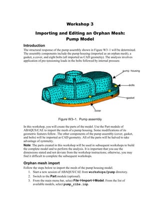
  • 1. Workshop 3 Importing and Editing an Orphan Mesh: Pump Model Introduction The structural response of the pump assembly shown in Figure W3–1 will be determined. The assembly components include the pump housing (imported as an orphan mesh), a gasket, a cover, and eight bolts (all imported as CAD geometry). The analysis involves application of pre-tensioning loads in the bolts followed by internal pressure. Figure W3–1. Pump assembly In this workshop, you will create the parts of the model. Use the Part module of ABAQUS/CAE to import the mesh of a pump housing. Some modifications of its geometric features follow. The other components of the pump assembly (cover, gasket, and bolts) will be imported as CAD geometry. All of the parts will be halved to take advantage of symmetry. Note: The parts created in this workshop will be used in subsequent workshops to build the complete model and to perform the analysis. It is important that you use the dimensions stated and not deviate from the workshop instructions; otherwise, you may find it difficult to complete the subsequent workshops. Orphan mesh import Follow the steps below to import the mesh of the pump housing model. 1. Start a new session of ABAQUS/CAE from workshops/pump directory. 2. Switch to the Part module (optional). 3. From the main menu bar, select FileImportModel. From the list of available models, select pump_ribs.inp. pump housing gasket cover bolts
  • 2. 4. ABAQUS/CAE takes a few seconds to import the model. Once the model is imported, you will be in the Assembly module. Switch back to the Part module. Notice a new model (named pump_ribs) that contains the imported part (named PUMP–1) has been created. The model appears as shown in Figure W3–2. Figure W3–2. Orphan mesh of pump housing Editing nodal coordinates Your first task will be to change the inner diameter of the hole that goes through the top of the pump. The coordinates of the nodes along the inner diameter need to be changed. Since these nodes lie on a circular surface, it will be advantageous to define a cylindrical coordinate system and simply change the radial coordinate of the nodes. Follow the steps below to achieve this task. 1. From the main menu bar, select ViewViews Toolbox. In the Views dialog box, select the 1–2 view. Turn off the perspective view by clicking the Turn Perspective Off tool ( ) and zoom into the component so that the hole is clearly visible (see Figure W3–3). Figure W3–3. Top view of pump housing 5. From the main menu bar, select ToolsDatum. The Create Datum dialog box appears (see Figure W3–4). Select CSYS as the datum type. Select the 3 points method, and click OK. When prompted for the type of coordinate system, choose W3.2
  • 3. Cylindrical. Place the coordinate system at the origin (0.0, 0.0, 0.0) and click Create Datum. A cylindrical datum coordinate system is created. The origin of the coordinate system coincides with the position of the center of the hole. Figure W3–4. Create Datum dialog box 6. You will now modify the inner diameter of the hole. From the main menu bar, select PartMesh Tools. In the Mesh Tools dialog box, select Node as the category and Edit as the method, as shown in Figure W3–5. Click OK to close the dialog box and proceed. Figure W3–5. Mesh Tools dialog box 7. You will be prompted to select the nodes to be modified. Begin by setting the selection filters as shown in Figure W3–6 by clicking the Show/Hide Selection Options tool, in the prompt area. W3.3
  • 4. Figure W3–6. Selection filters 8. The nodes can be selected in one of two ways: · Try selecting the nodes individually (the default selection technique) using a Circular Drag Shape. The center of the drag shape should be the center of the cylindrical coordinate system defined earlier (see step 2). Select a perimeter point for the drag shape such that you include all the nodes on the inside surface of the hole. The selected nodes will be highlighted in red after the selection, as shown in Figure W3–7. You may wish to rotate your model to check whether all the nodes have been selected properly. · You may also select the nodes using the face angle method (i.e., by specifying the maximum deviation in the angle between adjacent element faces). This technique is generally more efficient than selecting the nodes individually: all nodes that pertain to the element faces that satisfy the face angle criterion are automatically selected. In the prompt area, choose by face angle as the method by which the nodes will be selected. Then click on any element face located on the inner surface of the hole. The nodes on the inner surface are highlighted in red after the selection. As before, rotate your model to make sure all the nodes have been selected properly. Once you are satisfied with the selection (using either method), click Done in the prompt area. Figure W3–7. Modified nodes 9. The Edit Nodes dialog box appears, as shown in Figure W3–8. This dialog box will be used to change the diameter of the hole. Click Select in the upper right corner of the dialog box, and choose the cylindrical coordinate system defined in step 2 by clicking on it in the viewport when prompted to choose a local coordinate system. Select entities inside the drag shape Circular drag shape Toggle off the selection of entities closest to the screen W3.4
  • 5. 10. Using the Coordinates specification method, change the 1–coordinate (i.e., the radial coordinate) by selecting Specify from the pull down list and entering 0.65. Click OK to close the dialog box and then Done in the prompt area to complete the operation. Figure W3–8. Edit Nodes dialog box Deleting elements You will now remove the ribs on the pump housing and then you will remove half of the part. Begin by removing some of the elements in the rib located near the front of the housing, as shown in Figure W3–9. Use the 3–1 view from the Views Toolbox, and rotate the pump to view one of the front ribs, as shown in Figure W3–9. Figure W3–9. Rib elements 1. From the main menu bar, select PartMesh Tools. In the Mesh Tools dialog box, select Element as the category and Delete as the method. Click OK. 11. When prompted to select the elements to be deleted, use the Show/Hide Selection Options tool to change the drag shape to a Polygon. Select some of the elements located near the 90 bend of the rib, as shown in Figure W3–9. 12. In the prompt area, toggle on Delete associated unreferenced nodes. 13. Zoom out and rotate the view to confirm that only elements pertaining to the ribs have been selected. If any other elements are highlighted, deselect them using [Control]+Click. When you are satisfied with the selection, click Done to delete the elements and their associated nodes. 14. The remaining ribs on the pump housing can be removed by selecting them carefully in a similar fashion. However, this can be a tedious and time-consuming W3.5
  • 6. process for large, complicated models. To facilitate the process, you may delete selected sets. A. From the main menu bar, select PartMesh Tools. In the Mesh Tools dialog box, click OK to continue deleting elements. B. In the prompt area toggle on Delete associated unreferenced nodes. C. In the prompt area, click Sets to open the Region Selection dialog box. In this dialog box, select the set RIBS and toggle on Highlight selections in viewport to highlight the elements belonging to this set. D. Click Continue to delete the remaining rib elements. E. Click Cancel to close the dialog box. You will now halve the pump housing. Use the 1–2 view from the Views Toolbox to facilitate element selection. 15. From the main menu bar, select PartMesh Tools. In the Mesh Tools dialog box, click OK to continue deleting elements. 16. In the prompt area, toggle on Delete associated unreferenced nodes. Tip: If the Region Selection dialog box appears, click Select in Viewport on the right side of the prompt area so you can select elements in the viewport. 17. Select the upper half of the pump housing for deletion, as shown in W3–10. When you are satisfied with the selection, click Done to delete the elements and their associated nodes. The half pump housing without the ribs is shown in Figure W3–11. 18. Save the model database. Name the model database file PumpAssy.cae. W3.6
  • 7. Figure W3–10. Select half of the pump housing. Figure W3–11. Halved pump housing without ribs Importing CAD geometry You will now import the remaining components of the assembly into ABAQUS/CAE. 19. From the main menu bar, select FileImportPart to open the Import Part dialog box. 20. In this dialog box, set the file type to ACIS SAT. From the list of available files, select cover.sat. Click Continue in the dialog box to proceed. 21. In the Create Part from ACIS File dialog box, select the Import - Repair tab and toggle on all the available repair options. Click OK to close the dialog box and continue. The imported part is shown in Figure W3–12a. 22. After the part is imported, use the Geometry diagnostics part query tools (ToolsQuery) to check for any invalid or imprecise entities. 23. Repeat steps 2 through 4 to import the part defined in file gasket.sat. The imported part is shown in Figure W3–12b. 24. Import the part defined in file n_bolts.sat without any repair options turned on. The imported part is shown in Figure W3–12c. 25. Review the different parts of your model. Query the important dimensions using the Query tools and note them for future reference. 26. Save your model database as PumpAssy.cae. W3.7 rectangular drag shape selected elements
  • 8. Figure W3–12. Components of pump assembly Halving the imported geometry You will now remove half of each of the imported parts. Begin with the cover. 1. From the Part list located under the tool bar, select cover to access the cover geometry. 27. From the main menu bar, select ViewSpecify. Using the Viewpoint method, enter the coordinates of the viewpoint as 0,0,-1 and the coordinates of the up vector as 0,-1,0. Click OK to apply the view and close the dialog box. Next, create a datum axis using the steps outlined below. This axis will be used to orient the part in the sketch plane when creating the cut profile. 28. From the main menu bar, select ToolsDatum. 29. In the Create Datum dialog box, choose Axis as the type and Principal Axis as the method. Click OK. 30. Choose the principal Y-Axis as the datum axis. 31. From the main menu bar, select ShapeCutExtrude. 32. Select the top surface of the cover, indicated in Figure W3–13, as the plane on which to sketch. W3.8 (a) cover (b) gasket (c) bolts
  • 9. Figure W3–13. Sketch plane and datum axis 33. Select the datum axis as the edge that will appear vertical and on the right of the sketch. 34. From the main menu bar, select AddLineRectangle. Sketch a rectangle enclosing the upper half of the cover, as shown in Figure W3–14. Figure W3–14. Cut profile 35. Click mouse button 2 to continue, and click Done in the prompt area. 36. In the Edit Cut Extrusion dialog box, choose the end condition Through All. The direction of extrusion is into the cover. Click OK. The final cover geometry is shown in Figure W3–15. Figure W3–15. Cover W3.9 sketch plane datum axis cut rectangle
  • 10. Similarly, halve the gasket and bolt parts. 2. From the Part list located under the tool bar, select gasket to access the gasket geometry. Use the 1–2 view from the Views Toolbox. 37. As before, define the datum axis to orient the part. From the main menu bar, select ToolsDatum. 38. In the Create Datum dialog box, click OK to create another Axis using the Principal Axis method. Choose the principal Y-Axis as the datum axis. 39. From the main menu bar, select ShapeCutExtrude. 40. Select the top surface of the gasket as the plane on which to sketch, as shown in Figure W3–16. Select the datum axis as the edge that will appear vertical and on the right of the sketch. 41. From the main menu bar, select AddLineRectangle. Sketch a rectangle enclosing the upper half of the gasket, as shown in Figure W3–16. Figure W3–16. Cut profiles 42. Click mouse button 2 to continue, and click Done in the prompt area. 43. In the Edit Cut Extrusion dialog box, choose the end condition Through All. The direction of extrusion is into the gasket. Click OK. 44. Repeat steps 12 through 19 to remove four of the bolts from the part named n_bolts. Note that the top surface of any of the bolts to the left of the datum axis may be used as the sketch plane for the extruded cut. The final gasket and bolt parts are shown in Figure W3–17. 45. Save the model database as PumpAssy.cae. W3.10 (a) gasket (b) bolts surfaces selected as sketch planes cut rectangle
  • 11. Figure W3–17. Gasket and bolts W3.11 (a) gasket (b) bolts