1. | 1 |
TRANSACTIONS OF 61st INDIAN FOUNDRY CONGRESS 2013
INTRODUCTION
The Computerised simulation technique is used here to
analyse the defects found in castings.
HOT TEAR DEFECTS
Hot tear is a defect that occurs during solidification of a
casting. Though steel is poured at high temperature, this
temperature is low relative to high freezing temperature
range for steel. The result of this is that steel starts
freezing soon after being poured, often before the moulds
and cores have been heated to the point where they have
lost their bond strengths. These facts coupled with the
relative large contraction of steel alloys make steel
castings susceptible to Hot Tears (Figs. 2 and 3).
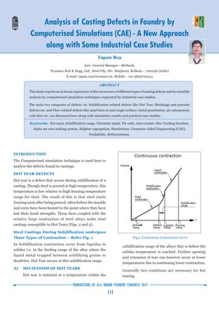
Steel Castings During Solidification undergoes
Three Types of Contraction – Refer Fig. 1
In Solidification contraction occur from liquidus to
solidus i.e. in the feeding range of the alloy where the
liquid metal trapped between solidifying grains or
dendrites. Hot Tear occurs at this solidification range.
A) MECHANISM OF HOT TEARS
Hot tear is initiated at a temperature within the
Analysis of Casting Defects in Foundry by
Computerised Simulations (CAE) - A New Approach
along with Some Industrial Case Studies
solidification range of the alloys that is before the
solidus temperature is reached. Further opening
and extension of tear can however occur at lower
temperatures due to continuing lower contraction.
Generally two conditions are necessary for hot
tearing.
Tapan Roy
Asst. General Manager - Methods,
Texmaco Rail & Engg. Ltd., Steel Fdy. Div. Belgharia, Kolkata – 700056 (India)
E-mail: tapan.roy@texmaco.in, Mobile.: +91-9836700315
ABSTRACT
This study reports an in house experience of the occurrence of different types of casting defects and its scientific
analysis by computerised simulation techniques supported by industrial case studies.
The main two categories of defects viz. Solidification related defects like Hot Tear, Shrinkage and porosity
defects etc. and Flow-related defects like sand burn in and rough surface/ metal penetration, air entrapment,
cold shut etc. are discussed here along with simulation results and practical case studies.
Keywords: Hot tears, Solidification range, Chromite sands, Tie rods, Anti-cracker ribs/ Cooling brackets,
Alpha set core making system, Sulphur segregation, Simulations, Computer-Aided Engineering (CAE),
Feedability, Refractoriness.
Fig.1: Continuous Contraction Curve
2. | 2 |
TRANSACTIONS OF 61st INDIAN FOUNDRY CONGRESS 2013
a) There must be resistance to contractions.
b) There must be variable temperature gradients
within the casting section.
Fig.2: Hot tear defects.
Fig.3: Hot tear defects at junctions.
B) PREVENTION OF HOT TEAR
There is usually no easy or single cure for consistent
elimination of hot tears, because many factors can
contribute for the formation of hot tears.
The most common precautionary measures
are as follows :
a) Moulding Materials - Strong, hard moulds
and cores that collapse slowly under heat is
more likely to cause hot tears than weak,
easily collapsible moulds and cores. Resin
bonded sand mixes (especially alpha set –
ester cured system) offer lower resistance to
tearing than sodium silicate bonded sand
system.
Whenever possible mould and core section
should be hollowed out or notch should be
provided at the corners of the hollow block as
per Fig.5 for better collapsibility or a
collapsible insert such as polystyrene
(thermocol) incorporated into the section as
close as possible to the casting surface.
Alternately Paper tubes may be inserted at the
corners for better collapsibility Fig.6. Binder
level and rammed density should be kept to a
minimum level.
b) Steel Quality- Sulphur and Phosphorous
level should be kept below 0.02% and the
Mn:S ratio at least 25:1. Deoxidation at a level
avoid deleterious Type II grain boundary
inclusions.
c) Hydrogen in Steel – The solubility of
Hydrogen in molten steel is 27 ppm. While in
solid condition hydrogen has very poor
solubility. The dissolved hydrogen in molten
steel during solidification comes out and
causes hydrogen embrittlement. The stress
developed during solidification causes hot
tear and has led to a numbers of catastrophic
failure e.g. in Bogie items of Indian Railways.
By understanding the sources of hydrogen in
greater detail it has been possible in
optimising steelmaking processes, minimising
hydrogen pickup, and more importantly,
minimising Hot Tear defects.
d) Pouring Temp.- Pour at a minimum
temperature consistent with avoiding cold
metal defects and maintain high fill rate.
e) Feeding Practice – Adequate feeding of
isolated hot spots can prevent the formation
of hot tears. Excessive large feeders which may
hinder contraction should be avoided.
3. | 3 |
TRANSACTIONS OF 61st INDIAN FOUNDRY CONGRESS 2013
f) Gating Practice- Multiple gates should be
used to even out temperature gradients and
locally overheated mould parts should also be
avoided.
Care should be taken to ensure that the design
of runners and gates is not “tying” the casting
and restricting normal contraction. Over
filling of the pouring basin which results in
flash across the top of the moulding box can
also contribute to contraction restrain.
Chromite or Zircon sand can be effective in
preventing tears in thin sections particularly
in fillets and junctions Fig.4, 12, 16 and
Cooling bracket or anti cracker ribs can help
reduce tears in fillet and their thickness
should be less than 0.25 the thickness of the
casting sections Fig.15.
Fig.4 : Chromite sands in core for chilling.
Fig.5 : Hollow block with notch effect to arrest Hot Tear.
Fig.6 : Paper tubes for better collapsibility.
g) Casting Design - Good casting design with
uniform distribution of metal thickness can
reduce the incidence of tearing. Abrupt
change should be avoided, section changes
should be gradually blended and internal
cores should be adequately filleted.
k) Hot Tear due to Sulphur Segregation -
The segregated sulphur forms a low melting
point Fe-FeS eutectic. It is surprising that the
segregation of Mn does not help as the initial
sulphur is high. It is necessary to fix the
sulphur by calcium silicide addition. On
routine calcium silicide injection, the problem
of hot tear is largely eliminated confirming
that sulphur segregation is the main reason
for hot tearing.
CASE STUDY NO. 1
Hot Tear Defects Supported by (CAE) Simulation
Results
Figure 7, Bolster Wedge Pocket Simulation View shows
that the hot spot at the junctions. Temperature at this
region well within solidus range (temperature 1470°C)
and the metal at this area in mushy form, causing hot
tear during solidification.
4. | 4 |
TRANSACTIONS OF 61st INDIAN FOUNDRY CONGRESS 2013
Fig. 7: Showing hot zone (temp.1470°C).
Fig. 8: No hot zone (temp.1378°C).
Figure.8, Chromite sand placed at the wedge pocket area
improves the situation. Faster cooling causes the area to
solidify faster (temperature 1378°C) and no hot tear found
(Fig.12).
Fig.9: Showing hot zone (temp.1470°C).
Fig.10: No hot zone (temp.1380°C).
Figure 9 shows the simulation result of Centre pivot area
of Bolster castings. The view shows that the hot metal at
this junction whose temperature is 1470 °C, is well within
solidus range and is in mushy form and solidifies later
causing hot tearing due to contraction hindrances by
mould or core materials. But after positioning of external
chills, Fig. 11 at this area the temperature at this area was
found to be 1380 °C as per Fig.10, which indicates faster
cooling of this area and no hot tear was found.
Fig. 11: External chills to arrest hot tears.
Fig. 12: Chromite sands to prevent hot tears.
5. | 5 |
TRANSACTIONS OF 61st INDIAN FOUNDRY CONGRESS 2013
Fig.13: Showing hot zone (temp.1475°C).
Fig.14: No hot zone (temp.1206°C).
Figure 13 shows the simulation result of Pedestal area of
Side Frame castings. The view shows that the hot metal
at this junction whose temperature is 1475 °C, which is
well within solidus range and is in mushy form and
solidifies later causing hot tearing due to contraction
hindrances by mould or core materials. . But after
positioning of anti-cracker ribs inside (Fig.15) and
chromite sands outside (Fig.16), the temperature at this
area was found to be 1206 °C as per Fig.14, which indicates
faster cooling of this area and no hot tear was found.
CASE STUDY NO. 2
Rough Surface Finish / Poor Surface Finish
Description of Causes – Sands due to high
temperature of molten metal or low refractoriness of base
sands, or due to poor quality of bentonite or high moisture
of processed sands, or soft moulds or improper or no
painting of moulds fuse at the casting surface that stick
to the surface is called rough surface finish of the castings
(Fig. 17).
REMEDIES
1) Moisture content/Compactibility of
prepared sands
The moisture content should be in the range of 3.0
– 3.5 % for HPML, 4–4.5% for semi-mechanised
moulding to get good surface.
Too high moisture makes rough surface. Too low
moisture makes friable surface. Compactability
should be in the range of 42-48 % for HPML.
2) High Clay Content in Process Sand
The total clay content in process should not be
more than 12 % and the dead clay content should
not be more than 4 % (max.).
Fig.15: Anti-cracker ribs to arrest hot tear.
Fig.16: Chromite sands at corners.
6. | 6 |
TRANSACTIONS OF 61st INDIAN FOUNDRY CONGRESS 2013
Fig.17: Castings produced in High Pressure Moulding and
Semi-mechanised moulding.
3) Temperature of the Sand – The hot sand causes
rough surface problem. The temperature of the
process sand should not be more than 45 °C.
4) Grain Fineness Nos.- Finer sands give good
surface finish & coarser sands give rough surface.
5) Compactness of the Mould / Core -
Compactness of the mould is very important for
getting good surface finish of the casting. High
mould hardness gives good surface finish of the
castings. On the other hand low hardness gives poor
surface and swelled mould.
6) Gating System i.e. Ingate Location and Size
– The position of the ingate plays a vital role for
the surface finish of the castings. For steel castings,
ingate located at the bottom of the casting gives
good surface finish.
7) Pouring Temp. - The temperature of pouring is
very vital for the surface finish of the castings. The
tapping temperature of Mild steel should be 1580
– 1600 O
C. High pouring temperature causes poor
surface.
8) Mould Wash and Core Wash Quality- The
base i.e. zircon or magnesite content in paint is
important for getting good surface finish. At least
60% zircon carried by alcohol or water is essential
for getting good surface finish. Moreover binder
present in the carrier plays a vital role. In ready to
use paint addition of external carrier causes poor
quality as it contains no binders.
9) Quality of Incoming Sands Used - The Silica
(SiO2
) content plays a vital role in getting good
surface finish. For Low carbon steel the silica
content should not be less 98%.
10) Bentonite Quality – The quality of bentonite is
vital as in using sodium based bentonite gives good
bonding and less quantity is required. But for
calcium based bentonite more quantity is required
and gives poor surface.
Simulation view as per Fig.18 shows that due to
heavy hot spot the metal at this area remains hot at
this area for a longer time causing Sand sticking and
its effect in real casting as per Fig.19.
So, thick zircon-based coating or double coating at
this area ensures elimination of sand sticking
defects.
CASE STUDY NO. 3
Sand fusion found at the bottom part of support casting
as per Fig.20.
Simulation view as per Fig.20 shows that Sand fusion
found at the bottom part of the mould is due to higher
temperature of moulding sands ranging from 479°C to
938°C. But at the top side there is less sand fusion due to
low mould temperature ranging from 173°C to 402°C.
CASE STUDY NO. 4
Shrinkage defects found in Bogie casting (Bolster) due
to potential hot spot found at junction of casting as per
simulation given in Fig.21 & 22.
7. | 7 |
TRANSACTIONS OF 61st INDIAN FOUNDRY CONGRESS 2013
Fig.18: Simulation view of Hot Zone of Pivot casting causing sand fusion.
Fig. 19: Sand fusion in real casting
Fig.20: Sand Fusion.
The simulation view shows that there is a potential Hot
spot to be fed by the risers as at that time there were only
two elliptical risers.
Fig.21: Hot Spot at the junction.
Fig.22: Shrinkage found at the junction.
But now there are 4 round risers at these hot spot areas
(Fig. 23).
CASE STUDY NO. 5
Air entrapment problems in Green Sand moulds
produced in High Pressure Moulding Line in support
items.
8. | 8 |
TRANSACTIONS OF 61st INDIAN FOUNDRY CONGRESS 2013
Fig.23: After modification and positioning 4 nos. round risers
no shrinkage found at this area.
Fig.24: Simulation view of support showing air
entrapment during filling of moulds.
CASE STUDY NO. 6
Cold shut problems found in support item at the end due
to improper filling.
Fig.26: Cold shut at the end.
Fig. 25: 3 Nos. vents at the end of the casting.
Fig. 27: Flow offs and feeder at the end.
3 vents at the end of support casting were provided for
easy escape of entrapped gases and to eliminate air
entrapment problems (Figs. 24 and 25).
9. | 9 |
TRANSACTIONS OF 61st INDIAN FOUNDRY CONGRESS 2013
3 flow offs and 2 feeders are added at the end of support
casting to eliminate cold shut problems. As the cold shut
occurs due to back pressure of air on the flowing metal,
provision were made for escape of gases and thus cold
shut was removed (Figs. 26 and 27).
CONCLUSIONS
From the above study it can be concluded that the defect
analysis done by simulation help a practical foundry man
to take decision and corrective actions can be taken to
eliminate these defects with lesser efforts.
REFERENCES
1. Hot Tears in Steel Castings – By J.F.Meredith, Articles
published in Metal Casting Technologies of Vol. 53, No. 2,
June 2007.
2. Directional Solidification of Steel Castings, R.Wlodawer.
3. Principles of Metal castings, Heine Loper and Rosenthal,
Second Edition, McGraw-Hill.
4. Metal Casting, Computer-Aided Design and Analysis, Dr.
B.Ravi, Published by Prentice -Hall of India, New Delhi,
2005.
5. Gas Analysis in Steel: Identifying, Quantifying, and
Managing Hydrogen Pick-up in Steel, Charles R. Hurst,
Product Engineer, Heraeus Electro-Nite Australia, Ir. M.
Vergauwens, Product Manager, Heraeus Electro-Nite
International N.V.
6. Simulation of the Components done by Auto Cast-X CAD
Simulation Techniques and ADSTEFAN, Japanese Casting
Simulation Software developed by HITACH, JAPAN.