Vortex Flowmeter with Built-in Temperature Sensor

With a temperature sensor incorporated into the flow rate sensor, "Multivariable Type" vortex flow meters enable both fluid temperature measurement and flow rate measurement simultaneously, thereby achieving multi- sensing functions such as various correction calculations based on measured temperature data as represented by steam mass flow rate calculations. This paper outlines the structure, functions and features of "digitalYEWFLO Multivariable Type" vortex flow meters using data from verification tests at actual users' plants. Paper courtesy of Yokogawa Corporation of America. For more information in the New York / New Jersey Metropolitan area contact: Miller Energy 3200 South Clinton Ave. South Plainfield, NJ 07080 Phone: 908-755-6700 Toll Free: 800-631-5454 Fax: 908-755-0312 www.millerenergy.com

Recomendados
Recomendados
Mais conteúdo relacionado
Mais de Miller Energy, Inc.
Mais de Miller Energy, Inc. (20)
Último
Último (20)
Vortex Flowmeter with Built-in Temperature Sensor
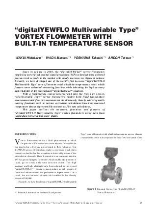
- 1. “digitalYEWFLO Multivariable Type” Vortex Flowmeter With Built-in Temperature Sensor 21 “digitalYEWFLO Multivariable Type” VORTEX FLOWMETER WITH BUILT-IN TEMPERATURE SENSOR WAKUI Hidekazu *1 WADA Masami *1 YOSHIOKA Takashi *1 ANDOH Tetsuo *1 Since its release in 2001, the “digitalYEWFLO” vortex flowmeters employing our original spectral signal processing (SSP) technology have achieved proven track records in the market with steady increases in shipment volume. Recently, we have developed one of the world’s first two-wire “digitalYEWFLO Multivariable Type” vortex flowmeters with a built-in temperature sensor, which features more enhanced measuring functions while inheriting the high accuracy and reliability of the conventional “digitalYEWFLO” products. With a temperature sensor incorporated into the flow rate sensor, “Multivariable Type” vortex flowmeters enable both fluid temperature measurement and flow rate measurement simultaniously, thereby achieving multi- sensing functions such as various correction calculations based on measured temperature data as represented by steam mass flow rate calculations,. This paper outlines the structure, functions and features of “digitalYEWFLO Multivariable Type” vortex flowmeters using data from verification tests at actual users’ plants. *1 Industrial Automation Business Headquarters INTRODUCTION Vortex flowmeters utilize a fluid phenomenon in which frequencies of Karman vortex streets released from a shedder bar inserted in a flow are proportional to flow velocities. Our YEWFLO series of flowmeters employ a system in which stress caused in a shedder bar due to vortexes is detected by means of two piezoelectric elements. These flowmeters were commercialized in 1979 as general-purpose flowmeters which enable measurement of liquid, gas or steam in the same detection section. Their high accuracy and high reliability have been retained in the present “digitalYEWFLO” (1) products, incorporating as well a series of functional enhancements and performance improvements. As a result, the total number of units sold worldwide has already exceeded 200,000. Recently, we have developed a “digitalYEWFLO Multivariable Figure 1 External View of the “digitalYEWFLO” Vortex Flowmeter Type” vortex flowmeter with a built-in temperature sensor, wherein a temperature sensor is incorporated into the flow rate sensor of the
- 2. 22 Yokogawa Technical Report English Edition, No. 37 (2004) Piezoelectric element 1 Piezoelectric element 2 Temperature sensor (Pt1000) “digitalYEWFLO” vortex flowmeter. This product enables measurement of fluid temperatures and provides new functions such as various correction calculations using the measured data. The external view is the same design as the standard type digitalYEWFLO products, as shown in Figure 1. PRINCIPLE OF MEASUREMENT Basic Principle of the Vortex Flowmeter Frequencies f of Karman vortex streets released from a shedder bar inserted in a flow and volume flow rates Q have the following relationship: f = K · Q K: K factor Optimum selection of shapes and dimensions of shedder bars makes it possible for the K factor to become an almost constant value within a wide range of Reynolds numbers. As a result, the measurement of vortex frequencies f makes it possible to measure volume flow rate Q. Flow Rate Correction Calculation The “digitalYEWFLO Multivariable Type” products use fluid temperatures measured by the built-in temperature sensor to enable various flow rate correction calculations, which are mainly as follows: (1) Mass flow rate of steam Mass flow rate M can be measured by obtaining fluid density ρ from fluid temperatures using the steam density table provided in the internal memory (the pressure under operating conditions needs to be set for superheated steam) and by multiplying fluid density ρ with volume flow rate Q: M = ρ · Q (2) Volume flow rate of gas under standard conditions Volume flow rate Qn under standard conditions can be measured by performing temperature pressure corrections based on Boyle’s Law and Charles’ Law. Qn = Q · (P/Pn) · (Tn/T) · (1/k) Qn : volume flow rate under standard conditions Q : volume flow rate under operating conditions P : pressure under operating conditions * Pn : pressure under standard conditions * T : absolute temperature under operating conditions Tn : absolute temperature under standard conditions * k : deviation coefficient * (*: to be set by the user) (3) Mass flow rate of liquid Mass flow rate M can be measured by correcting density changes caused by fluid temperatures according to the following quadratic equation: M = ρn · Q · { 1 ϩ a1 (t Ϫ tn) ϩ a2 (t Ϫ tn)2 } ρn : density under standard conditions * Q : volume flow rate under operating conditions a1 : primary correction coefficient * a2 : secondary correction coefficient * t : temperature under operating conditions tn : temperature under standard conditions * (*: to be set by the user) CONFIGURATION Detector Figure 2 shows a cross section of the detector (sensor). The temperature sensor is incorporated near the lowest part of the robust flow rate sensor made of stainless steel. The temperature sensor uses a platinum temperature-indicating resistor Pt1000 (equivalent to JIS Class A). Powdered MgO which has a high heat conductivity rate is packed around the temperature sensor. One of the important applications of “digitalYEWFLO” products is the fluid measurement of gas that includes steam. In general, the specific heat capacity or heat conductivity rate of gas is low. Temperature tends to change easily in terms of both space and time. Thus, accurate temperature measurement has been considered to be difficult. In order to solve this problem, we have employed the following structures: (1) The temperature sensor is positioned near the lowest part of the flow rate sensor in order to reduce temperature measurement errors due to the influences of heat radiation around the converter housing on the upper part of the flow rate sensor when high-temperature fluids are measured. (2) Powdered MgO which has a high heat conductivity rate is packed around the temperature sensor in order to minimize heat resistance between fluids and the temperature sensor. These structures have facilitated the realization of highly accurate temperature measurements even under harsh measurement conditions such as steam. Figure 2 Cross Section of the Detector (Sensor)
- 3. “digitalYEWFLO Multivariable Type” Vortex Flowmeter With Built-in Temperature Sensor 23 Converter Figure 3 shows the circuit configuration of the signal processing part of the converter. With digitized signal processing, the “digitalYEWFLO” flowmeters realized the implementation of conventional analog signal processing circuits (such as an adder, a band pass filter, and a schmitt trigger) in a gate array. This allowed for the reduction of the number of parts used, thus achieving a more compact converter. Signals detected by two piezoelectric elements are converted into digital signals via charge converters and A/D converters. The adder adds the outputs of A/D converters 1 and 2 according to a noise ratio optimum for the reduction of vibration noise. Signals processed in the band pass filter are turned into pulses in the Schmitt trigger circuit. Then, the frequencies of these pulses are calculated in the CPU to become flow rate signals. On the other hand, the signals of the Pt1000 temperature sensor are converted into digital signals in the pre-amp and A/D converter 3 to become temperature signals in the CPU. Flow rate signals undergo various calculations, such as the temperature correction calculation, and are output as 4 to 20-mA analog and contact pulses from the output circuit. Moreover, communication means make it possible to read not only flow rate values but also temperature values. Thus further improved convenience is realized when a “digitalYEWFLO Multivariable Type” vortex flowmeter is used in conjunction with the Fieldbus communication protocol, which enables transmission of multiple measured values from a single measuring instrument (e.g., a flowmeter). Display The display allows for two levels of indications, providing increased information on a single screen. These indications can be selected as follows: Upper level: flow rate or percentage (%) indication Lower level: total rate or temperature indication (with unit indications for both) Figure 4 shows examples of a flow rate on the upper level and a temperature reading on the lower level. In addition, if the occurrence of an error is confirmed in the self-diagnosis function, an error number will be indicated. If a parameter has been set, its parameter number will be indicated on the upper level, while the setting value will be indicated on the lower level. Parameters can also be set using the three setting keys provided on the front of the display. Moreover, the display can be mounted at 90-degree increments in three different directions. Figure 3 Circuit Configuration of the Signal Processing Part of the Converter Figure 4 Examples of Indications Piezoelectric element 1 Counter Temperature sensor (Pt1000) LCD display Output circuit Pre-amp A/D converter 3 Adder Charge converter 1 Charge converter 2 A/D converter 1 A/D converter 2 Noise ratio setting Piezoelectric element 2 Gate array Band pass ilter Schmitt trigger CPU Flow rate
- 4. 24 Yokogawa Technical Report English Edition, No. 37 (2004) APPLICATION An application using a “digitalYEWFLO Multivariable Type” vortex flowmeter for the mass flow rate measurement of saturated steam is outlined below. The line in the example used a combination of a vortex flowmeter, a temperature sensor, a pressure gauge and a flow rate calculator to control mass flow rates by means of temperature pressure corrections. We additionally mounted a “digitalYEWFLO Multivariable Type” vortex flowmeter in the line and compared the flow rate measurement test using this vortex flowmeter with the same test using the existing multiple instruments. Figure 5 shows the results of these output comparison tests, which clearly indicate that the outputs of the “digitalYEWFLO Multivariable Type” vortex flowmeter agree with those of the mass flow rate calculations made by the existing multiple instruments, including the traceability to detailed flow rate fluctuations. This comparison demonstrated that a single “digitalYEWFLO Multivariable Type” vortex flowmeter can replace multiple instruments in controlling mass flow rates of steam (Figure 6). Figure 5 Mass Flow Rate Measurement of Saturated Steam Figure 6 Streamlined Measurement (Example) CONCLUSION The latest “digitalYEWFLO Multivariable Type” vortex flowmeter is mainly targeted for steam applications. In the midst of growing energy control demand for environmental protection and energy conservation, “digitalYEWFLO Multivariable Type” vortex flowmeters have made it possible to substantially streamline existing measurement systems. As a result, these flowmeters have enabled the reduction of customers’total costs of ownership (TCO), including the initial deployment costs and maintenance costs. The “digitalYEWFLO Multivariable Type” vortex flowmeter is our pioneering product to incorporate the multi-sensing functionality which will become one of the mandatory requirements for sensors in the field network era. We are firmly committed to the continuous evolution and advancement of the YEWFLO series of products in order to meet the growing demand of our customers. REFERENCE (1) Hondo Masanori, et al., “A Vortex Flowmeter with Digital Signal Processing ‘digitalYEWFLO’,” Yokogawa Technical Report, Vol. 45, No. 3, 2001, pp. 183–186 (in Japanese) * digitalYEWFLO and YEWFLO are registered trademarks of Yokogawa Electric Corporation. Other names of products and models that appear in this document are registered trademarks or the trademarks of the respective holders.Vortex flowmeter Temperature sensor Pressure gauge Flow rate calculator [Temperature] [Pressure] [Mass flow rate] Outputs of flow rate calculations using multiple instruments (red) “digitalYEWFLO Multivariable Type” vortex flowmeter readings (blue)