
Recomendados
Mais conteúdo relacionado
Mais procurados
Mais procurados (19)
Destaque
Destaque (20)
Semelhante a Understanding Electric Current
Semelhante a Understanding Electric Current (20)
Mais de matcol
Mais de matcol (15)
Understanding Electric Current
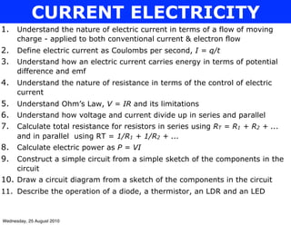
- 1. CURRENT ELECTRICITY 1. Understand the nature of electric current in terms of a flow of moving charge - applied to both conventional current & electron flow 2. Define electric current as Coulombs per second, I = q/t 3. Understand how an electric current carries energy in terms of potential difference and emf 4. Understand the nature of resistance in terms of the control of electric current 5. Understand Ohm’s Law, V = IR and its limitations 6. Understand how voltage and current divide up in series and parallel 7. Calculate total resistance for resistors in series using RT = R1 + R2 + ... and in parallel using RT = 1/R1 + 1/R2 + ... 8. Calculate electric power as P = VI 9. Construct a simple circuit from a simple sketch of the components in the circuit 10. Draw a circuit diagram from a sketch of the components in the circuit 11. Describe the operation of a diode, a thermistor, an LDR and an LED Wednesday, 25 August 2010
- 2. ELECTRIC CURRENT Power Supply An electric current is a flow of charge + - Electric charge flows around a simple circuit and under the influence of a power supply (the energy source). A simple circuit is a conducting path around which charge can flow. A conducting path Two models of electric current: • Electron flow - electrons in wires flow from the positive to the negative terminal of a power supply. • Conventional current - The direction in which positive charge would move if it could - this is the model that we use in physics http://regentsprep.org/Regents/ physics/phys03/bsimplcir/default.htm Wednesday, 25 August 2010
- 3. ELECTRIC FIELDS When there is a power supply and a wire conducting path an electric field is set up in the wire. We consider that positive charge would flow from the positive to the negative end of the electric field: Power Supply + - +++ Potential difference + + + A (i.e. voltage) is how much more potential energy a unit of charge has B at A than it has at B - - - A conducting path Note (i) The electric field in a wire is uniform. (ii) As charge flows in the field it loses potential energy. (iii) The minimum potential energy that charge has is at the negative terminal of the power supply. Wednesday, 25 August 2010
- 4. CIRCUITS Current - is the rate of flow of electrical charge - it is the number of coulombs of electrical charge that passes a point in one second. where I = electric current (Cs-1 or A) I=Q Q = electric charge (C) t t = time (s) Note Cs-1 reads Coulomb per Second V + - Consider the simple circuit I I When voltage, V is increased the energy difference between a coulomb of charge on either side of the power supply will increase. This energy difference drives electrons around the circuit faster. In other words, as supply voltage increases then current will also increase (provided that the resistance remains constant) Wednesday, 25 August 2010
- 5. Potential difference (i.e. Voltage) is the energy difference that a coulomb of charge has on either side of a component (Formal definition) where V = potential difference or voltage (Volts, V) V = ∆Ep ∆Ep = change in potential energy that a charge q experiences when it moves from one side to the other side of a component (Joule, J) q = the unit of charge (Coulomb, C) Unit of Voltage: Joule per Coulomb or Volt (JC-1) or (V) Example V Consider the voltage across a lamp: - + A B 1A If V = 6V then a coulomb of charge has 6J more electrical potential energy at point A than it does at point B Assignment questions 1 & 2 Wednesday, 25 August 2010
- 6. RESISTANCE Definitions 1. Resistance, R is a measure of the “electrical friction” in a conductor. (the opposition to the flow of current) 2. It is the ratio of the voltage across a conductor to the current through it. Resistance = Voltage Current R=V Unit of resistance is the ohm, Ω I Resistance is given by the slope or gradient of a voltage - current graph Example In an experiment, the voltage across a lamp is measured and recorded as the current is increased 1 A at a time. Calculate the resistance of the lamp. V (V) 24 20 16 12 8 4 0 1 2 3 4 5 6 I (A) Wednesday, 25 August 2010
- 7. OHM’S LAW Ohm’s Law states that the voltage across a resistor is proportional to the current through it. i.e. V α I A resistor that obeys Ohm’s Law has a voltage - current graph that is a straight line so the resistance is always a constant value: V Vα I The gradient of the graph is R So V = RI or V = IR I Ohm’s law is usually written this way Note Ohm’s law allows us to calculate the correct voltage when the current in the circuit changes. This requires knowledge of the resistance and requires the value of the resistance to stay the same regardless of the current. A conductor which obeys Ohm’s Law is called an Ohmic conductor. Wednesday, 25 August 2010
- 8. LIMITATIONS OF OHM’S LAW 24 V (V) 20 When a temperature of a lamp increases its 16 resistance increases 12 8 4 I (A) 0 1 2 3 4 5 6 For most conductors, as the temperature increases the increased vibration of particles impedes the flow of electrons. Resistance in the conductor will therefore increase. The graph slopes upwards. V (V) 24 The resistance of a thermistor decreases as its 20 16 temperature decreases 12 8 4 I (A) 0 1 2 3 4 5 6 Wednesday, 25 August 2010
- 9. RESISTANCE CALCULATIONS Resistors which are connected end to end are in series with one another R1 R2 The total resistance of the series combination, Rs is the sum of the resistances R1 and R2. For two or more resistors in series: Rs = R1 + R2 + ........... Resistors which are connected side by side are in parallel with each other. R1 R2 The total resistance of the parallel combination, Rp is less than any individual resistor in the combination. For two or more resistors in parallel 1 1 1 + .... the total resistance,Rp is given by: RP = R1 + R2 Wednesday, 25 August 2010
- 10. Examples CALCULATING TOTAL RESISTANCE 100 Ω 100 Ω 2 1 3 100 Ω 100 Ω 100 Ω 100 Ω 100 Ω • • 100 Ω • • Total resistance = 100 Ω 100 Ω • • Total resistance = Total resistance = 4 100 Ω 5 100 Ω 100 Ω 100 Ω • • • • 100 Ω 100 Ω 100 Ω Total resistance = Total resistance = Assignment question 3 Wednesday, 25 August 2010
- 11. VOLTAGE AND CURRENT IN SERIES CIRCUITS + - VT A1 A3 I1 I3 I2 A1 V1 V2 Current in series is constant I1 = I2 = I3 Voltage in series is shared VT = V1 + V2 Note Voltage is shared in proportion to the size of the resistance Wednesday, 25 August 2010
- 12. PARALLEL CIRCUITS + - Current in parallel is shared IT VT IT IT = I1 + I2 I1 R1 in other words “charge splits up as it enters a junction in a circuit” V1 I2 R2 Voltage in parallel is constant V2 VT = V1 = V2 Note Current is shared in an inverse proportion to the size of the resistance. For example: If R1 = 5 and R2 = 10 and IT = 3 “Double the resistance then halve the current” then I1 = 2 and R2 = 1 Wednesday, 25 August 2010
- 13. http://phet.colorado.edu/simulations/ CIRCUIT CONSTRUCTION sims.php? sim=Circuit_Construction_Kit_DC_Only 1. Enter the URL (above) into the address bar of your internet browser. 2. Use the simulation tools to construct each of the following 3 circuits (ensure that you use identical lamps and an the same power supply for each circuit). 3. Record the current in each circuit and explain your observation. 4. Repeat this exercise for the second set of 3 circuits. 1 2 3 + - + - + - A A A 3 + - 2 A 1 + - + - A A Wednesday, 25 August 2010
- 14. Examples CIRCUIT CALCULATIONS 1 + 9V - A1 V1 A3 5Ω 10Ω A2 V2 V3 For the circuit represented by the circuit diagram above, what is the reading on: (a) V1 (b) A2 (c) V2 (d) V3 Wednesday, 25 August 2010
- 15. 2 + 15V - V1 5Ω A3 V2 A1 V3 R 10Ω A2 For the circuit represented by the circuit diagram above, what is the reading on: (a) V3 if V2 = 10 V (b) A1 (c) A2 (d) A3 (e) What is the value of resistor R? Wednesday, 25 August 2010
- 16. 3 + 12V - V1 2Ω 4.8Ω V3 A1 V2 3Ω A2 For the circuit represented by the circuit diagram above, what is the reading on: (a) V1 (b) V3 (c) V2 (d) A1 (e) A2 Assignment questions 4, 5 & 6 Wednesday, 25 August 2010
- 17. Examples APPLIANCES IN THE HOME p167 ABA Q5 & 6 1. The diagrams opposite show two different heating circuits for a hot plate. Both circuits use two similar heating elements, A and B, of equal resistance. (b) Draw a circuit diagram for each circuit. 240 V 240 V (b) Consider circuit 1. The current flowing through element A is measured to be 1.2 A. What is the current through element B? _____________________________________ (c) How much current is drawn by circuit 1 from the mains? _________________________________________________________________ (d) Explain why the voltage across element A is 120 V. _________________________________________________________________ _________________________________________________________________ (e) Calculate the resistance of each heating element. _________________________________________________________________ _________________________________________________________________ Wednesday, 25 August 2010
- 18. Consider circuit 2 (f) Explain why the current through element A is 2.4 A. _________________________________________________________________ _________________________________________________________________ (g) How much current is drawn from the mains? _________________________________________________________________ (h) Calculate how much electric power is turned to heat by the circuit. _________________________________________________________________ _________________________________________________________________ (i) How many times more heat is generated in circuit 2 than in circuit 1. _________________________________________________________________ 2. A stereo uses 240 V and the combined resistance of all its internal components is 60Ω. (c) Calculate the power rating of the stereo. __________________________________________________________________ (d) Calculate the amount of energy used to operate the stereo for half an hour. __________________________________________________________________ __________________________________________________________________ Wednesday, 25 August 2010
- 19. 3. A set of 10 Christmas tree lights operate from a 20 V supply. They are all similar 1.0 W bulbs, connected in parallel. (a) Calculate the voltage across each bulb. (b) Calculate the current through each bulb, in mA. (c) Calculate the resistance of each bulb. (d) Calculate the total resistance in the circuit. 4. A 1000 W iron is connected to a 120 V supply. Should the iron need to be used on a 240V supply calculate the size of the resistance that will need to be added in series to the iron so that the iron continues to draw the same current. Assignment question 7 Wednesday, 25 August 2010
- 20. SPECIALIZED COMPONENTS Thermistor A thermistor is a resistor which is sensitive to heat. Unlike most resistors though its resistance decreases as its temperature increases. This makes it useful in the circuit in your car that contains the temperature gauge. The temperature gauge is an ammeter calibrated to read temperature instead of Amps and the thermistor is in contact with the engine and connected in series with the gauge. As the engine temperature increases the resistance of the thermistor decreases thereby allowing the current in the circuit to increase. This increase in current is reflected in the reading on the gauge. Light dependent resistor An LDR is a resistor which is very sensitive to light. Its resistance decreases with light intensity. They are useful in light meters where the meter is essentially an ammeter re-calibrated to read lux instead of Amps. Wednesday, 25 August 2010
- 21. Diode Because a diode allows current to flow in one direction only, it is called a semiconductor. Diodes require only a low voltage (about 0.6 V) and will only allow a small current to flow through them. They are useful in circuits that convert AC current to DC. Light emitting diode These give off light as they allow current to flow one way through a circuit. They require about 2 V to function. Because of their low power input they are useful for lights (eg. they are finding their way into the tail light clusters of motor vehicles) Wednesday, 25 August 2010
- 22. 12 PHYSICS ELECTRICITY ASSIGNMENT Name ______________________ 1. 1. Draw using arrows, the direction of charge flow in each circuit 2. For each circuit, highlight the lamps that will + - + - (a) (b) + - + - (c) (d) Wednesday, 25 August 2010
- 23. + - + - (e) (f) 2. Write the correct term (from the word list) into the column (left) Term Definition Word list the unit of charge impede the unit of work or energy parallel the difference in the potential energy per coulomb of charge between electric field two points in an electrical circuit the unit for potential difference constant a region within which a charge experiences a force Ohm’s law electrical friction or a measure of the ability of a conductor to conduct potential electricity difference relationship between resistance, voltage & current where the resistance series remains constant. to slow down or resist volt connected “one after the other” in a circuit coulomb connected “side by side” in a circuit joule used to describe quantities that remain the same resistance Wednesday, 25 August 2010
- 24. 3. Calculate the effective resistance, R of the following combination of resistors: (a) R <=> R= (b) R R= <=> (c) R <=> R= Wednesday, 25 August 2010
- 25. (d) A 12V battery supplies 1.5 A to a circuit as shown in the diagram. 12 V A voltmeter will read 10 V when it is 2A connected between two points in the 1Ω 2Ω 3Ω above circuit. Which two points? (Show all working below) A B C D (e) (i) Describe the change in the total resistance in the circuit as R increases from 1Ω to 2Ω to 3Ω. 2Ω R V (ii) Explain how the total current, I changes as R changes. (iii) How is the voltage, V affected by these changes? Wednesday, 25 August 2010
- 26. 4. For the following circuit answer the questions which follow: (a) Calculate the total current, IT which flows through the circuit. (b) Calculate the current through the 1Ω resistor. (c) Calculate the size of the current which would flow through the circuit if another 1Ω resistor was added in parallel to the 1Ω and 2Ω already in the circuit. Wednesday, 25 August 2010
- 27. 5. A 30V battery supplies a current of 3A to the circuit shown: 30 V (a) Calculate the voltage across AB. + - 3A R 8Ω R A B (b) Calculate the current through R 3Ω (c) Determine the value of R (d) Explain why adding a 100000 Ω resistor in parallel to the lamp will not cause the brightness of the lamp to change Wednesday, 25 August 2010
- 28. 6. In the circuit shown the ammeter has negligible resistance and reads 2.5 A. (a) Calculate the current, I (b) Calculate the value of R. Wednesday, 25 August 2010
- 29. 7. Questions (a) to (e) refer to the circuit (right): (a) Calculate the total resistance in the circuit (b) Show that the unknown resistance R is 3.0 x 10⁴ Ω (c) Calculate the power dissipated by the 1.0 x 10⁴ Ω resistor (d) Calculate the power delivered by the battery (e) The battery is left on for 24 hours (f) Calculate the energy delivered in this period of time (g) Where did this energy go? Wednesday, 25 August 2010
- 30. Wednesday, 25 August 2010
- 31. Wednesday, 25 August 2010
- 32. ELECTROMAGNETISM 1. Understand that an electric current creates a magnetic field around itself 2. Describe the magnetic field created by a straight current-carrying wire 3. Describe the magnetic field created by a solenoid 4. Use the right-hand slap rule to predict the direction of the magnetic force on a current-carrying wire in a magnetic field 5. Use F = Bqv to calculate the size and direction of the magnetic force on a moving charge inside a magnetic field 6. Describe the circular motion of a charged particle inside a magnetic field 7. Understand electromagnetic induction in terms of the relative motion between a coil and a magnetic field. 8. Use V = Bvl to calculate the voltage induced across a wire moving through a magnetic field 9. Describe the operation of the electric generator Wednesday, 25 August 2010
- 33. ELECTRIC CURRENTS AND MAGNETIC FIELDS Charm compass N Magnetic field lines The compass needle is itself a tiny magnet (the S North pole of this magnet points towards the South end of the magnet) Area of strong magnetic field strength • Magnetic field strength depends on the density of the magnetic field lines. • Uniform field: field lines are parallel A magnetic field is produced when electrons in an object display a common pattern of motion. The smallest magnetic field is the magnetic field of a single electron. • When there is random electron motion, the magnetic fields of the electrons cancel each other. This results in no net field being produced. Wednesday, 25 August 2010
- 34. A circular magnetic field is formed around a straight current - carrying conductor: For each of the views, draw the magnetic field lines around the wire 3D View View from above • The direction of the magnetic field lines is given by the Magnetic Field Strength Symbol: B ~ Right-hand Thumb Rule Magnetic field strength is a vector quantity since it has both magnitude and direction Unit of B: Newton per Amp per metre (N A-1 m-1) or Tesla (T) Wednesday, 25 August 2010
- 35. THE SOLENOID The magnetic field of a solenoid is similar in shape to that of a bar magnet: Draw the magnetic field lines around the solenoid If the current is known, the poles of the solenoid can be determined using the right hand thumb rule for solenoids: Thumb points to North pole of the solenoid from inside the coil Curled fingers indicate the direction of the current Wednesday, 25 August 2010
- 36. Field lines are parallel in the core of the solenoid which --> the magnetic field in the core is uniform. The density of magnetic field lines is greatest in the core --> the magnetic field strength is greatest in the core. Magnetic Field Strength, B is: - proportional to current, I B α I - proportional to the number of turns of wire per unit length of the coil, n i.e. B α n http://www.phy.ntnu.edu.tw/ntnujava/main.php?t=276 Ex 17A: Q.1 to 5 Wednesday, 25 August 2010
- 37. MOTOR EFFECT • A current carrying conductor in a magnetic field will experience a force. • This is seen as movement when the conductor hangs in the magnetic field of a bar magnet The force is maximum when the angle between the conductor and the magnetic field lines is 90o The size of the force can be increased by: (i) increasing the current (ii) increasing the magnetic field strength (iii) increasing the length of the wire in the field The direction of the force can be predicted using the right hand slap rule. The DC motor: http://www.walter-fendt.de/ph14e/electricmotor.htm Wednesday, 25 August 2010
- 38. THE RIGHT HAND SLAP RULE FOR CONVENTIONAL CURRENT Direction of Direction that a Magnetic field positive charge would flow (direction of conventional current) The direction of the force is given by the direction of the slap - into the board in this case A LEFT HAND SLAP RULE CAN BE USED FOR ELECTRON FLOW Wednesday, 25 August 2010
- 39. Side view of the hanging wire: N Magnetic field lines on LHS of wire oppose each other and repel ----> weak field F Magnetic field lines on the RHS of the wire bunch up ----> strong field Draw the magnetic field lines S which explain the direction of the The wire experiences a force which is to the left force Examples 1. The following images all show conductors in a magnetic field. In which of the following situations is the force on the conductor directed out of the page. magnetic field electric current out of page out of page I I A B B C D E ~ • • • • B • • • • I ~ • • • • • • • • • • • • • Wednesday, 25 August 2010
- 40. 2. A copper wire is carrying an electric current. It is placed between the poles of a magnet. The magnetic force on the wire pushes it into the page, as shown. (a) Label the poles of the magnet as North and South. (b) Where is the stronger field, in front or behind the wire? __________________ (c) What would happen if the wire was made of aluminium? _______________________________________________________________ (d) What would happen if the wire was rotated (to the right) so it is horizontal. _______________________________________________________________ Wednesday, 25 August 2010
- 41. 3. The current balance is a device that is like a see-saw. One end of the see-saw is inside a solenoid. The other end has a mass (m) on it that can be adjusted to achieve a balance. It is able to measure the magnetic force on a conductor in a magnetic field. The uniform field inside the solenoid of the current balance (shown) has a strength of 10-2 NA-1m-1. CD (a straight section of the conductor at right angles to the magnetic field) is 2 cm long and carries a current of 1 A. Side view m x Board Pivots Pivot Current into the page (a) Show the direction of the force on CD using an arrow drawn on the side view . (b) What is the magnitude of the force on CD? (c) What mass, m is needed to be placed on the other end to maintain balance? Wednesday, 25 August 2010
- 42. 4. For each of the devices illustrated (the mechanism that drives an ammeter needle on the left and a loudspeaker on the right), explain how they work. Assume the ammeter needle rotates clockwise and the loudspeaker is pushing outwards to the right. (Draw on the diagram to assist you in your explanation) ammeter loud speaker This coil is attached to the cone cone Cylindrical S magnet N S N S View of cylindrical magnet from the front Wednesday, 25 August 2010
- 43. F α B F = B Il applies to a conductor which is perpendicular F α I to the magnetic field F α l where: F = force on the conductor (N) B = magnetic field strength (T) I = Electric current (A) l = length of the conductor in the magnetic field (m) I N B ~ S l Wednesday, 25 August 2010
- 44. F F Wednesday, 25 August 2010
- 45. Maximum torque exists F when the force is at right angles to the coil F F As the coil rotates, the angle that the force makes with the coil changes and the torque decreases. F Wednesday, 25 August 2010
- 46. F The torque is zero now because there is no component of the force that is perpendicular to the coil. No rotation F Decrease in torque as the coil continues F to rotate F Wednesday, 25 August 2010
- 47. Maximum torque again F F Note that the size of the force does not change as the coil rotates but the angle that the force makes with the coil does. The reason that the size of the force doesn’t change is because B, I and l do not change (Remember that F = BIl) Wednesday, 25 August 2010
- 48. THE MOTOR EFFECT AND THE SPEED OF MOVING CHARGES Consider a charge, q. It is one of many charges in a current-carrying wire moving with a velocity, v at right-angles to a magnetic field of strength, B: Since a moving charge constitutes an electric current in a magnetic field, the charge must experience a force which is at right angles to the velocity and the magnetic field. Apply the Left hand slap rule to the situation shown and confirm that the direction of the force is as it is represented in the diagram Deriving an expression for force: F = B Il (Equation 1) but I = q (Equation 2) t Substituting Eqn. 1 into Eqn. 2 gives: F = Bql => F = Bqv since v = l t t If the charge is an electron then: F = Bev where e is the charge on an electron and v is its speed. Wednesday, 25 August 2010
- 49. Example THE TV TUBE The diagram to the right shows the path of electrons along a TV tube. They travel at 20% of the speed of light. The TV tube is designed to x x x x xxxx provide a magnetic field in the direction shown, e x x x x xBx x x through which the electrons must travel. The x x x x x~x x field is 0.06 T into the page. x x x x xxxx (a) How fast are the electrons traveling in ms-1? ____________________________________ e = 1.602 x 10⁻¹⁹C (b) Calculate the force exerted on the electrons c = 3 x 10⁸ ms-1 as a result of the magnetic field. ____________________________________ ____________________________________ ____________________________________ (c) What is the direction of this force? _______________________ (d) Calculate the weight force on each electron. ______________________________ (e) Is this weight force significant? ________________________________________ (f) Explain the shape of the electron’s path. __________________________________________________________________ __________________________________________________________________ (a) 6 x 10⁷ ms-1 (b) 6 x 10-13 N (c) downwards initially and always at right angles to the path of the electron (d) 9 x 10-30 N (e) This weight is not significant. Much smaller that the magnetic force (f) The shape of the path is circular because there is a force at right angles to the electron’s velocity. Wednesday, 25 August 2010
- 50. Example CHARGE DEFLECTION IN A MAGNETIC FIELD One of the problems associated with the commercial harnessing of energy from a nuclear fusion reaction is that the enormously high temperatures make it very difficult to contain the hydrogen needed for the reaction. Magnetic fields provide a solution to the problem. At the temperatures involved the hydrogen atoms are ionized to positively charged protons. http:// surendranath.tripod.com/ Applets/Electricity/ MovChgMag/ MovChgMagApplet.html 9b.mass of electron A stream of protons is directed towards an area of magnetic field directed into the page as shown in the diagram. A proton is shown entering the field. (a) In which initial direction will it experience a force? ______________________ (b) On the diagram sketch the path of the proton while it is in the field. (c) Briefly explain how this phenomenon can help in solving the nuclear fusion problem. _______________________________________________________________ _______________________________________________________________ _______________________________________________________________ Wednesday, 25 August 2010
- 51. INDUCTION A current will be induced in a hanging wire when the wire is moved in a magnetic field This is the direction of a magnetic force on a positive charge A very sensitive meter could measure this current. If the hanging wire remained stationery and the magnet moved there would also be a current induced in the wire. An electric current will be induced in a conductor as long as there is relative movement between the _________ and the _________ field. There are 3 obvious ways of increasing the induced current: (i) ________________________________________________ (ii) ________________________________________________ (iii) ________________________________________________ Wednesday, 25 August 2010
- 52. INDUCTION and the right hand slap rule A current will be induced in a hanging wire when the wire is moved in a magnetic field. A very sensitive meter could measure this current. If the hanging wire remained stationery and the magnet moved there would also be a current induced in the wire. An electric current will be induced in a conductor as long as there is relative movement between the conductor and the magnetic field. The thumb points in Direction of the slap the direction in which Palm of shows the direction of the right hand magnetic force on a the wire is moved positive charge (conventional current) N B ~ S The fingers point in the l direction of Magnetic field Wednesday, 25 August 2010
- 53. Demo: Induction in the solenoid Observations North pole moved into the solenoid _______________________________________ The magnet is held stationery whilst the coil is moved towards it _______________ North pole stops inside the solenoid ______________________________________ North pole pulled out from inside the solenoid ______________________________ The rate of movement of the magnet is doubled ____________________________ Wednesday, 25 August 2010
- 54. INDUCED VOLTAGE Extra for experts DERIVATION OF V = Bvl Consider a wire moving with constant velocity, v in an external magnetic field. The wire is not part of a circuit. Electrons jump briefly to the right and accumulate at the right hand end of the wire and stop. These electrons jump because they are under the influence of a magnetic force, Fmag. “Thinking it through” x x x x v x x x x x x x x x x x x The left hand slap rule for e Fmag induction predicts the x x x x x x x x direction that the electron x x x x x x x x will jump. In this example they jump to the right. Wednesday, 25 August 2010
- 55. WHY DOES THE ELECTRON STOP? x x x x v x x x x Electrons quickly accumulate at the right end of the wire. This x x x x x x x x accumulation of electrons leads + - + e - to the formation of an electric - + force (as a result of the electric x x x Felec x x Fmag x x x field that forms) x x x x x x x x + x x x x v x x x x The electric force Felec quickly - + x x x x x x x x - increases in size as the charge + - accumulation increases until it is + e - equal in size to the magnetic - + force, Fmag. x x x Felec x x Fmag x x x - + - + x x x x x x x x - But because this fixed length of wire is not part of a circuit, no current will flow. The electrons will have stopped. When it is connected to a circuit, Fmag drives the current separation which causes it to act as a power supply. We say that there is a potential difference across the wire. Wednesday, 25 August 2010
- 56. WHY DOES THE ELECTRON JUMP IN THE FIRST PLACE?? Remember that the electron (with balanced forces acting on it) is not moving along the wire BUT it is moving across the magnetic field with speed v and so is experiencing a force given by F = Bev x x x x v x x x x x x x x x x x x e Fmag x x x x x x x x x x x x x x x x The direction of this magnetic force can also be predicted using the left hand rule for the motor effect. Wednesday, 25 August 2010
- 57. Felec = Fmag Ee = Bev (where B = the strength of the external magnetic field and e = the charge on an electron) Ve = Bev l Where V = the induced voltage (V) => V = Bv l B = the strength of the magnetic field (T) v = the speed with which the wire is moved l = the length of the wire In summary, the voltage induced in a wire in a magnetic field depends on the following factors: (i) The strength of the magnetic field (ii) The speed with which the wire is moved and (iii) The length of the wire in the magnetic field http://teacher.pas.rochester.edu/phy122/Lecture_Notes/Chapter32/chapter32.html Wednesday, 25 August 2010
- 58. A MOVING CONDUCTIVE LOOP IN A MAGNETIC FIELD DOES NOT HAVE A NET VOLTAGE INDUCED ACROSS IT v x x x x x x x x x x x x x x x x + e - + - x + x x x x x Fmag x x - x x x x x x x x LAMP WILL x x x x x x x x NOT GLOW x x x x x x x x x x x x x x x x x x x x x x x x + x x x x xe x x - x + - + x x x x x Fmag x x - x x x x x x x x x Current can not flow in the circuit Wednesday, 25 August 2010
- 59. Example An aircraft is flying directly over the North Magnetic Pole with a velocity of 300 kmh-1. The aircraft is pictured below as it would be viewed from above. (a) Which of the following diagrams best represents the direction of the magnetic field directly over the North Magnetic Pole as “viewed” from someone standing at this North magnetic pole (b) The free electrons in the wings of the aircraft experience a force. Is this force from P to Q or Q to P? _____________ Wednesday, 25 August 2010
- 60. (c) Would this change if the plane was going the opposite way? ______ (d) If the magnetic field is 2.0 NA-1m-1, what is the force on the single electron? _________________________________________________________________ _________________________________________________________________ (e) If the wing span is 8 m, what is the induced voltage across the wings when the electrons stop moving relative to the wing? _________________________________________________________________ _________________________________________________________________ (f) What are the two equal and opposite forces acting on the electrons when they stop moving relative to the wing? _________________________________________________________________ _________________________________________________________________ _________________________________________________________________ Answers: (a) up (b) Q --> P (c) Yes P --> Q (d) 2.7 x 10⁻¹⁷ N (e) 1333.3 V (f) Magnetic force = Electric force Wednesday, 25 August 2010
- 61. THE ELECTRIC GENERATOR A generator is based on a coil of wire which spins in a magnetic field. Because there is always relative motion between the wire and the field there will always be an induced current. Apply the Right hand slap rule for induction to 1 draw the direction of current flow through the coil in each of the following diagrams. Explain why the induced current through the coil during this phase of the generators rotation is zero 2 The alternator that charges the battery of a 3 car is an AC generator see web page below for the animation 4 http://www.walter-fendt.de/ph14e/generator_e.htm Wednesday, 25 August 2010
- 62. Example Diagram 1 (below) shows a loop of wire spinning between the two poles of a magnetic. Diagram 2 shows an electron in the right side of the loop. 0.4 0.25 0.35 (a) In what direction does the right vertical side of the loop move? (into or out of the page?) ___________________________________________ (b) Explain why the electron experiences a magnetic force. __________________________________________________________________ __________________________________________________________________ (c) Use the right hand slap rule for induction to determine the direction relative to the wire that the electron experiences this force. __________________________________________________________________ (d) Explain why there is no induced current in the loop for a brief instant when the loop has rotated 90o from the pictured position. __________________________________________________________________ __________________________________________________________________ Wednesday, 25 August 2010
- 63. (e) Explain why there is no induced current in the horizontal parts of the loop at any time during the rotation of the loop. __________________________________________________________________ __________________________________________________________________ The vertical sections of the loop are in uniform circular motion. The loop has a rotational speed of 50 rpm. (f) Calculate the period of the circular motion of one vertical section of the loop. Wednesday, 25 August 2010
- 64. Wednesday, 25 August 2010
- 65. Wednesday, 25 August 2010
- 66. Wednesday, 25 August 2010