VVC AUTO 85.5 - Smog Technician - Level 1 - Air fuel ratio_sensors
•Transferir como PPTX, PDF•
4 gostaram•1,621 visualizações


Recomendados
Recomendados
Mais conteúdo relacionado
Mais procurados
Mais procurados (20)
Destaque
Destaque (20)
Semelhante a VVC AUTO 85.5 - Smog Technician - Level 1 - Air fuel ratio_sensors
Semelhante a VVC AUTO 85.5 - Smog Technician - Level 1 - Air fuel ratio_sensors (20)
Mais de Justin Gatewood
Mais de Justin Gatewood (20)
Último
Último (20)
VVC AUTO 85.5 - Smog Technician - Level 1 - Air fuel ratio_sensors
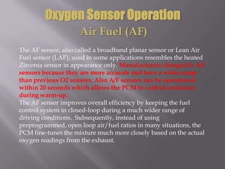
- 1. Oxygen Sensor Operation Air Fuel (AF) The AF sensor, also called a broadband planar sensor or Lean Air Fuel sensor (LAF), used in some applications resembles the heated Zirconia sensor in appearance only. Manufacturers changed to A/F sensors because they are more accurate and have a wider range than previous O2 sensors. Also A/F sensors can be operational within 20 seconds which allows the PCM to control emissions during warm-up. The AF sensor improves overall efficiency by keeping the fuel control system in closed-loop during a much wider range of driving conditions. Subsequently, instead of using preprogrammed, open loop air/fuel ratios in many situations, the PCM fine-tunes the mixture much more closely based on the actual oxygen readings from the exhaust.
- 2. Oxygen Sensor Operation Air Fuel (AF) AF sensors may be configured as seven-wire, five wire, or four-wire sensors. AF sensors cannot be visually identified by the number of wires they have. Always look at the under hood emissions label to determine if a vehicle is equipped with an Air/Fuel sensor.
- 3. Oxygen Sensor Operation Air Fuel (AF) AF sensors are used as the pre-catalyst (upstream) oxygen sensors. On a four-wire AF sensor, two wires are power and ground for the sensor heater, and the other two wires are used for the exhaust mixture signal.
- 4. Oxygen Sensor Operation Air Fuel (AF) The Air Fuel oxygen sensor heater is designed to heat the oxygen sensor thimble to a minimum of 1200 F. This temperature is double that of an early four-wire sensor and is required for the AF sensor to properly sample the exhaust oxygen content. When the AF sensor heater is commanded on by the PCM, approximately 8 amps of current should be flowing through the circuit.
- 5. Oxygen Sensor Operation Air Fuel (AF) The PCM controls the voltage to a fixed voltage. It is difficult to confirm the AF sensor voltage without a scan tool as the voltages at the terminals are fixed and any change is noted within the PCM itself. The voltage signal is proportional to the change in the air/fuel mixture. This allows the PCM to more accurately judge the exact air/fuel ratio under a wide variety of conditions and quickly adjust the amount of injector pulse. Think of the AF sensor as a generator that is capable of changing polarity.
- 6. Oxygen Sensor Operation Air Fuel (AF) The AF sensor has two zirconia elements that share a diffusion chamber. The AF sensor is really two O2 sensors in one unit. There are three chambers in the AF sensor: • The first chamber contacts the exhaust flow. • The diffusion chamber between the elements. • The air reference chamber.
- 7. Oxygen Sensor Operation Air Fuel (AF)
- 8. Oxygen Sensor Operation Air Fuel (AF) The first chamber is really the outside of the sensor, which contacts the exhaust. The diffusion chamber is the area between the two zirconia elements and the air reference chamber is at the other end. The basic operating principle behind the AF sensor is that by controlling the amount of O2 in the diffusion chamber, you can control its operating range. One of the zirconia elements acts as an oxygen pump. We discussed how a flow of oxygen ions creates a flow of electrons. The inverse is also true. A flow of electrons applied to the sensor causes a flow of ions. This is what happens when you charge a car battery.
- 9. Oxygen Sensor Operation Air Fuel (AF) Notice how the elements are wired in parallel, and there is a common ground lead. This ground is a reference point for the ECM. Do not confuse it with the vehicle ground. In fact, if you measure the voltage between the sensor ground and the vehicle ground, you will see about 2.7 volts.
- 10. Oxygen Sensor Operation Air Fuel (AF) For this explanation, we will distinguish the two zirconia elements by calling one, sensor #1 and the other, sensor #2. The ECM monitors the voltage between sensor #1 input and the ground lead. The ECM tries to hold the voltage difference between sensor #1 and the ground lead to 450 mV.
- 11. Oxygen Sensor Operation Air Fuel (AF)
- 12. Oxygen Sensor Operation Air Fuel (AF) When the mixture goes rich, oxygen ions flow from the diffusion chamber to the exhaust. The voltage on sensor #1 input increases. The ECM detects the voltage increase and reduces the voltage on sensor #2 input.
- 13. Oxygen Sensor Operation Air Fuel (AF) The voltage on sensor #2 input then goes more negative than the ground voltage. This causes sensor #2 to pump oxygen out of the diffusion chamber into the air reference chamber. When the oxygen content of the diffusion chamber drops, the voltage on sensor #1 drops. At the same time that the ECM reduces the voltage on sensor #2 input, it is also reducing fuel delivery.
- 14. Oxygen Sensor Operation Air Fuel (AF) When the mixture goes lean, oxygen ions flow from the exhaust into the diffusion chamber. The voltage on sensor #1 input decreases. The ECM detects the voltage decrease and increases the voltage on sensor #2 input. The voltage on sensor #2 input goes more positive than the ground voltage. This causes sensor #2 to pump oxygen into the diffusion chamber from the air reference chamber. The voltage between sensor #1 input and ground is consistently held at 450 mV.
- 15. Oxygen Sensor Operation Air Fuel (AF) The PCM knows how rich or lean the exhaust is by how much amperage it supplies to sensor #2 input to hold sensor #1 input voltage to 450 mV. • Positive amperage the mixture is lean. • Negative amperage the mixture is rich.
- 16. Oxygen Sensor Operation Air Fuel (AF) Rich Mixture Lean Mixture Zero Volts
- 17. Please wait for video to load and play.