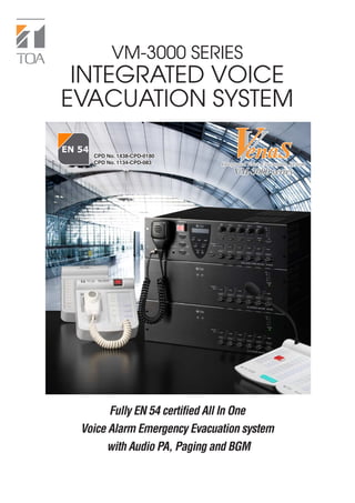
1. VM-3000 SERIES
INTEGRATED VOICE
EVACUATION SYSTEM
CPD No. 1438-CPD-0180.
CPD No. 1134-CPD-083. Integrated Voice Evacuation System
VM-3000 series
Fully EN 54 certified All In One
Voice Alarm Emergency Evacuation system
with Audio PA, Paging and BGM
2. High-quality, compact public address system
also features safety-enhancing emergency ev
SYSTEM FEATURES
• Max. 13 MIC/LINE Inputs
(VM-3240VA/3360VA: 4 MIC/LINE Inputs,
VM-3240E/3360E: 9 Local Inputs)
• 2 BGM inputs
• Up to 4 Fireman's/Remote Microphones connectable
(max. 2 Fireman's Microphones)
• Max. 60 assignable speaker zone outputs
(6 outputs per amplifier)
• Volume setting possible for each zone
• Digital audio processed & controlled
• Full digital audio mixing (DSP)
• Built-in high quality electronic voice message
• Intuitive configuration
• Zone setting, priority setting, failure detection setting by
dedicated PC software
• LCD display of current status and configuration setting of
system units
Emergency functions
• Continuous speaker line monitoring without
interruption of BGM distribution or paging
announcements
• Complete fault detection and indication
• Off-site log check capability via LAN
• Built-in and remote Fireman's Microphones
• Built-in voice alarm message
• 2-Phased voice alarm message (Alert and
Evacuation) broadcasting
Paging functions
• 2 Remote Microphone interface lines
• Paging (All zones/Group/Individual)
• 2-channel broadcast with external amplifier
(Paging/BGM)
3. for s
small and medium venues
vacua
uation functions.
Integrated Voice Evacuation System
VM-3000 series
TOA, which boasts 50 years' experience in the development of emergency broadcast
systems worldwide, now introduces a system that fully integrates emergency and
general-purpose broadcast functions. The TOA VM-3000 Series is an EN 54 Standard-
compliant combined emergency voice alarm system and public address system that was
developed as part of the Venas Integrated Voice Evacuation System family. TOA has
developed and will continue to develop emergency broadcast systems, always ensuring
that its products comply with the voice evacuation safety standards, established by the
countries where those products are used.
The VM-3000 Series is ideal for small and medium-sized applications. It incorporates such
emergency functions as continuous speaker line monitoring and a built-in voice alarm.
This easy-to-install system also offers PA broadcasting, paging and BGM functions that
ensure consistently high intelligibility.
The VM-3000 Series is digitally audio processed and controlled, and may be set up and
operated directly by using the controls and LCD display on the front panel. A dedicated
PC software configuration capability is also provided for establishing settings via LAN.
The incorporation of wide-ranging functional capabilities, superb reliability and versatility
make the VM-3000 a highly cost-effective emergency broadcast system.
4. for small and medium venues
acuation functions.
Integrated Voice Evacuation System
VM-3000 series
SPECIFICATIONS *0dB = 1V
VM-3240VA VM-3360VA VM-3240E VM-3360E
Voice Alarm System Amplifier Voice Alarm System Amplifier VM Extension Amplifier VM Extension Amplifier
Power Source 230V AC, 50/60 Hz
Power Consumption 600W (with rated output signal), 850W (with rated output signal), 600W (with rated output signal), 850W (with rated output signal),
260W (according to EN60065) 380W (according to EN60065) 260W (according to EN60065) 380W (according to EN60065)
Rated Output 240W 360W 240W 360W
Frequency Response 50 – 20,000 Hz, ±3dB (at 1/3 rated output)
Distortion Under 0.7% (at rated output, 1kHz)
S/N Ratio Over 85dB
Audio Input/Output Sampling frequency: 48kHz —
Characteristic A/D D/A CONVERTER: 24bit
Input Input 1 – 3: -50dB* (MIC)/-10dB (LINE) (changeable) 600Ω, electronically balanced Local input: -50dB* (MIC)/-10dB* (LINE)
combined XLR connector (female)/phone jack External amplifier input: 100V line, removable terminal block (14 pins)
Input 4: -50dB* (MIC)/-10 dB (LINE) (changeable) 600Ω, electronically balanced
removable terminal block(14 pins)
BGM 1 – 2 : -10 dB, 10kΩ unbalanced, RCA pin jack
External amplifier Input: 100V Line removable terminal block(14 pins)
Output Speaker output 1 – 6: Speaker output 1 – 6: Speaker output 1 – 6: Speaker output 1 – 6:
Total within 240W, removable terminal Total within 360W, removable terminal Total within 240W, removable terminal Total within 360W, removable terminal
block (14 pins) block (14 pins) block (14 pins) block (14 pins)
Direct output : Direct output from Direct output : Direct output from Direct output : Direct output from Direct output : Direct output from
internal or external amplifier, internal or external amplifier, internal or external amplifier, internal or external amplifier,
removable terminal block (16 pins) removable terminal block (16 pins) removable terminal block (16 pins) removable terminal block (16 pins)
Recording output BGM / Paging: Recording output BGM / Paging:
0dB*, 10kΩ, unbalanced, RCA pin jack 0dB*, 10kΩ, unbalanced, RCA pin jack
RM Link Input 1 – 2: Connecting the RM-300MF/RM-200M Remote Microphone. —
RJ45 female connector
Link cable: Category 5 Shielded Twisted-Pair straight cable (CAT5-STP)
Network I/F 10 BASE-T/100 BASE-TX (selectable by automatic negotiation), —
RJ45 female connector
Link cable: Category 5 Shielded Twisted-Pair straight cable (CAT5-STP)
VM Link Output: Connecting the VM-3240E or VM-3360E, RJ45 female connector Input: Connecting the VM-3240VA or VM-3360VA, RJ45 female connector
Link cable: Category 5 Shielded Twisted-Pair straight cable (CAT5-STP) Output: Connecting the VM-3240E or VM-3360E, RJ45 female connector
Link cable: Category 5 Shielded Twisted-Pair straight cable (CAT5-STP)
EXT PA Link Connecting the VP-2421, RJ45 female connector
Link cable: Category 5 Shielded Twisted-Pair straight cable (CAT5-STP)
General Control Input 1 – 8: No-Voltage make contact input, open voltage: 24V DC, short-circuit current: under 2mA, removable terminal block (14 pins)
Output 1 – 8: Isolated open collector output, withstand voltage: 30V DC, operating current: under 10mA, removable terminal block (14 pins)
Emergency Control Input 1 – 5: No-Voltage make contact input, open voltage : 24V DC, short-circuit current: under 2mA, RJ45 female connector
Input 6: Isolated voltage input: Inactive; -24V ±20%/Active; +24V ±20%, RJ45 female connector
Status out: Relay contact output, withstand voltage: 40V DC, operating current: 2 – 300mA, RJ45 female connector
ATT Control Relay contact 1 – 6, 125V AC or 30V DC, total under 5A, removable terminal block (16 pins)
Power Input/Output Power in: Connecing the VX-2000DS Power in: Connecing the VX-2000DS Power in: Connecing the VX-2000DS Power in: Connecing the VX-2000DS
(operating range: 20 - 40V DC) (operating range: 20 - 40V DC) (operating range: 20 - 40V DC) (operating range: 20 - 40V DC)
PS out: DC 28V/18A PS out: DC 28V/24A PS out: DC 28V/18A PS out: DC 28V/24A
M4 Screw terminal distance between M4 Screw terminal distance between M4 Screw terminal distance between M4 Screw terminal distance between
barriers 11 mm barriers 11 mm barriers 11 mm barriers 11 mm
DC24V Output 24V DC, Maximum feeding current 0.3A
DS Link Connecting the VX-2000DS, RJ45 female connector
Link cable: Category 5 Shielded Twisted-Pair straight cable (CAT5-STP)
Operating Temperature –5°C to +45°C
Operating Humidity 5% to 95%RH (no condensation)
Dimensions 482 (W) × 132.6 (H) × 431.2 (D)mm 482 (W) × 132.6 (H) × 407 (D)mm
Weight 16.5kg 19kg 16.5kg 19kg
Accessories Power cable (2m) × 1, Setting software (CD) × 1, Link cable (3m) × 2, Power cable (2m) × 1, Link cable (3m) × 2, Plastic foot × 4,
Plastic foot × 4, Plastic foot mounting screw × 4, Emergency microphone × 1, Plastic foot mounting screw × 4, Removable terminal plug (14 pins) × 3,
Removable terminal plug (14 pins) × 3, Removable terminal plug (16 pins) × 1 Removable terminal plug (16 pins) × 1
Option Input transformer: IT-450 —
VM-3240VA/3360VA VM-3240E/3360E
5. RM-300MF RM-320F
Fireman's Microphone Fireman's Microphone Extension
Power Source 24V DC (operating range: 15 – 40V DC, supplied from the VM-3000 system or VX-2000DS.) —
Current Consumption 120mA (RM-300MF), 660mA (with 3 RM-320F connected) 180mA max. (RM-320F)
Frequency Response 200 – 15,000 Hz —
Distortion Under 1% —
S/N Ratio Over 55 dB —
Microphone Unidirectional dynamic microphone with talk key, compressor (on/off switchable) —
Volume Control Microphone volume control / Buzzer volume control —
Connection Cable Main line: shielded CPEV cable (each one pair of Audio line, Data line, —
Power supply line) or Category 5 Shielded Twisted-Pair cable for LAN (CAT5-STP),
M3 screw terminal
No. of Connectable Max 3 units —
RM-320F
No of Funtion Keys — 20
Operation Emergency key, Evacuate key, Alert key, Emergency reset key, CPU switch, Reset switch —
Operating Temperature –5°C to 45°C —
Operating Humidity 5% to 95% RH (no condensation) —
Finish ABS resin, blueish gray ABS resin, blueish gray
Dimensions 200(W) x 215(H) x 82.5(D) mm 175(W) x 215(H) x 70(D) mm
Weight 1.1kg (with wall mounting bracket unit) 700g
Accessories Wall mounting bracket unit x 1, Wall mounting screw x 2, Electrical box mounting screw x 2 Wall mounting bracket x 1, Wall mounting screw x 2
RM-200M RM-210
Remote Microphone Remote Microphone Extension
Power Source 24V DC (operating range: 14 – 28V DC) —
Power input jack: Non-polarity type
Usable power input plug*2: Outer diameter ø5.5mm, inner diameter: ø2.1mm, length: 9.5mm
Current Consumption Under 100mA 20mA max. (in terms of RM-200M's DC power input)
Audio Output 0dB*: 600Ω, balanced —
Frequency Response 100 – 20,000 Hz —
Distortion Under 1% —
S/N Ratio Over 60 dB —
Microphone Unidirectional electret condenser microphone —
Volume Control Microphone volume control —
Connection Cable Category 5 Shielded Twisted-Pair cable, RJ45 connector —
and Connection
No of Funtion Keys 10 10
Finish ABS resin, blueish gray ABS resin, blueish gray
Dimensions 190(W) x 76.5(H) x 215(D) mm (Gooseneck microphone excluded) 110(W) x 76.5(H) x 215(D) mm
Weight 750g 350g
Accessory CATS cable x 1 CATS cable x 1
Option Wall mounting bracket: WB-RM200 Wall mounting bracket: WB-RM200
* 0dB = 1V
2 Use the AC adapter AD-246 or equivalent.
*
6. SYSTEM EQUIPMENT VX-200PS
VP-2241 (240 W × 1) Power Supply Unit
VP-2421 (420W × 1) The VX-200PS Power Supply Unit
Power Amplifier is mounted in the VX-2000PF
Power Supply Frame when in used.
Power Amplifier uses the VP-200VX Power Amplifier Input Module
per channel.
VX-2000PF
Power Supply Frame
The VX-2000PF permits the VX-200PS Power Supply Unit to be
mounted in an equipment rack. Up to 3 VX-200PS units can be
installed in the unit.
VX-2000DS
Emergency Power Supply
The VX-2000DS Emergency Power Supply Unit supplies the DC
power to VP amplifiersteach equipment, the VM-3000 system by
connecting the VM-3240VA/E/VM-3360VA/E and VX-200PS Power
Supply Unit. (Optional)
VM-300SV
Pilot Tone Detection Module
Speaker line failure can be detected with
high accuracy when a VM-300SV unit
specifically designed for 100V speaker line is connected
between the speaker line end and the emergency input terminal of
the VM-3240VA, VM-3360VA, VM-3240E, or VM-3360E.
SYSTEM EXAMPLE
RM-200M RM-300MF
Remote Fireman,s Zone 1
Microphone Microphone Audio Source
VM-3360VA (360W) Zone 2
AC mains Voice Alarm System Amplifier
AC Adapter Zone 3
VX-2000DS Zone 4
Emergency AC mains
Power Supply
Zone 5
VX-200PS
VP-2421 External amplifier Zone 6
Battery
VP-2421 External amplifier Zone 7-12
AC mains
VM-3360E (360W)
VM Extension Amplifier
VP-2421 External amplifier Zone 13-18
AC mains
VM-3360E (360W) RM LINK
PM-660U
VM LINK
Ext. PA LINK
Zone 19-24 DS LINK
AC mains
DC Power
VM-3240E (240W)
VP-2241 External amplifier
The Venas Series also includes the
EN 54 is a standard of the European Union (EU) for fire alarm systems, VX-2000 and SX-2000 higher-end models.
ensuring high product quality and reliability, and enabling better
integration of Voice Alarm (VA) and Public Address (PA). EN 54 plays a
significant role in the market for voice evacuation equipment, as the
member states of the European Union replace their local standards with
the EN 54 standard. All emergency voice evacuation systems marketed in the
members states of the European Union are required to be certified to this standard.
The VM-3000 system is certified on the European Norm EN 54-16 with
CPD number 1438-CPD-0180.
The VX-2000DS (ER/UK version) Power manager and VX-200PS (ER/UK version)
power supply are certified on the European Norm EN 54-4 with
CPD number 1134-CPD-083.
System compliant with EN 54
Human Society with
Security & Communication TOA Corporation
www.toa.jp
Specifications are subject to change without notice.
Printed in Japan (1105) 833-61-348-0D u