

Recomendados
Mais conteúdo relacionado
Semelhante a R38 Controller Appendix
Mais de Joseph
Último
Último (20)
R38 Controller Appendix
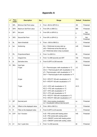
- 1. Appendix A n° Para meter Description Dec Range Default Protection 1 SPL Minimum Set Point value 0 From –99.9 to SPH E.U. -99 Protected 2 SPH Maximum Set Point value 0 From SPL to 999 E.U. 999 Protected 3 SP1 Set point 0 From SPL to SPH E.U. 0 Not Protected 4 SP2 Second Set Point 0 From SPL to SPH E.U. 0 Not Protected 5 AL Alarm threshold 0 From – 99.9 to 999 E.U. 0 Protected 6 tun Autotuning ALL = Performed at every start up onE = Performed at the first start up ub = Performed when U key is pressed onE Protected 7 Pb Proportional Band 0 From 1 to 200 E.U. 50 Protected 8 ti Integral time 0 From 1 to 999 seconds and OFF 100 Protected 9 td Derivative time 0 From 0 (OFF) to 200 seconds 25 Protected 10 SEn Input type F type A type T type JC = Thermocouple J with visualization in °C CA.C = Thermocouple K with visualization in °C JF = Thermocouple J with visualization in °F CA.F = Thermocouple K with visualization in °F Pt.C = RTD PT 100 with visualization in °C Pt.F = RTD PT 100 with visualization in °F nC.C = NTC with visualization in °C PC.C = PTC with visualization in °C nC.F = NTC with visualization in °F PC.F = PTC with visualization in °F P1C = RTD PT 1000 with visualization in °C P1C = RTD PT 1000 with visualization in °F J.C Pt.C nC.C Protected 11 DP Decimal point YES = Auto-ranging visualization no = Visualization without decimal point no Protected 12 CA Offset on the displayed value 0 From -300 to 300 E.U. 0 Protected 13 Ft Filter on the displayed value 0 From 0 (OFF) to 20 seconds 0 Protected 14 O1F Out 1 function H.rE = PID control with heating action C.rE = PID control with cooling action on.H = ON/OFF control with heating action on.C = ON/OFF control with cooling action HrE Protected 15 tr1 Out 1 cycle time 0 From 1 to 250 seconds 30 Protected
- 2. n° Para meter Description Dec Range Default Protection 16 o2F Out 2 function When o1F = H.rE or C.rE When o1F = on.H or on.C no = Not used HAL = Absolute high alarm LAL = Absolute low alarm b.AL = Band alarm (simmetric to the set point) dHA = Deviation high alarm dLA = Deviation low alarm no = Not used HAL = Absolute high alarm LAL = Absolute low alarm b.AL = Band alarm (simmetric to the set point) dHA = Deviation high alarm dLA = Deviation low alarm SP.C = SP2 - ON /OFF control with cooling action SP.H = SP2 – ON /OFF control with heating action nr = ON/OFF n nr = neutral zone Protected 17 d1 Out 1 hysteresis or neutral zone 0 From 1 to 999 E.U. 1 Protected 18 d2 Out 2 hysteresis 0 From 1 to 999 E.U. 1 Protected 19 ALF Alarm function AL = Automatic reset Alarm AL.n = Latched Alarm AL.A = Aknowledgeable Alarm AL Protected 20 ALt Inhibition time of the alarm at the start up or after a change of set point 0 From 0 (OFF) to 9.59 HH.mm 0 Protected 21 Pct Compressor protection time 0 From 0 (OFF) to 9.59 HH.mm 0 Protected 22 Sst Soft start time 0 From 0 (OFF) to 9.59 HH.mm 0 Protected 23 SSP Power during Soft Start 0 From 0 to 100% 0 Protected 24 UbF U key function no = No function Tun = It activates the manual tuning Sb = Stand-by mode Sb.o = Stand-By mode with display off tun Protected 25 PP Parameters protection Password 0 From 1 to 999 0 Protected 26 Lo Key lock time out 0 From 0 (key lock disabled) to 30 minutes 0 Protected