
Recomendados
Recomendados
Mais conteúdo relacionado
Mais procurados
Semelhante a Install oil pump cover and tighten screws
Semelhante a Install oil pump cover and tighten screws (7)
Último
Último (20)
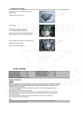
Install oil pump cover and tighten screws
- 1. Install the oil pump cover and tighten the screws to the specified torque. TORQUE:5N.m(0.5kgf.m,3.6lbf.ft) INSTALLATION Install the rotor shaft collar into crankcase Install a new gasket onto the oil pump body. Install the oil pump into the crankcase while aligning the pump shaft groove with the cam chain guide spindle lug Install and tighten the three screws to the specified torque. TORQUE:8N.m(0.8kgf.m,5.8ibf.ft) Install the clutch assembly(page9-12) SERVICE INFORMATION---------------------5-1 CARBURETOR ASSEMBLY--------------------5-6 TROUBLESHOOTIONG-----------------------5-2 CARBURETOR INSTALLATION----------------5-8 AIR CLEANER HOUSING---------------------5-3 AIR SCREW ADJUSTMENT---------------------5-10 CARBURETOR REMOVAL-------------------5-3 CRANKCASE BREATHER-----------------------5-11 CARBURETOR DISASSEMBLY-------------5-5 SERVICE INFORMATION GENERAL WARNING Gasoline is extremely flammable and is explosive under certain conditions. KEEP OUT OF REACH OF CHILDREN Bending or twisting the control cable will impair smooth operation and could cause the cable to stick or bind resulting in loss of vehicle control. Work in a well ventilated area. Smoking or allowing flames or sparks in the work area or where gasoline is stored can cause a fire or explosion. Refer to section 2 for fuel tank removal and installation. When disassembling fuel system parts, note the location of the O-ring. Replace them with new ones on reassembly Before disassembling the carburetor, place a suitable container under the carburetor drain tube. Loosen the screw and drain the carburetor. After removing the carburetor, wrap the intake port of the engine with a towel or cover it to prevent any foreign material from dropping into the engine. NOTE: If the vehicle is to be stored for more than one month, drain the float bowl, Fuel left in the float bowl may cause clogged jets, resulting in hard starting or poor drivability. LUBRICATION SYSTEM 5.FUEL SYSTEM COVER OIL PUMP
- 2. TROUBLESHOOTING Engine will not start ●Too much fuel getting to the engine Engine stall ,hard to start, rough idling -Air cleaner clogged ●Fuel line restricted -Flooded carburetor ●Ignition malfunction ●Intake air leak ●Fuel mixture too lean or too rich ●Fuel contaminated or deteriorated ●Fuel contaminated or deteriorated ●No fuel to carburetor ●Idle speed maladjusted -Fuel strainer clogged ●Float level maladjusted -Fuel tube clogged ●Fuel tank breather tube clogged -Float level maladjusted ●Air screw maladjusted -Fuel tank breather tube clogged ●Slow circuit clogged Lean mixture ●Fuel jets clogged After burn when engine braking is used ●Float valve faulty ●Lean mixture in slow circuit ●Float level too low ●Fuel line restricted ●Carburetor air vent tube clogged Backfiring or misfiring during acceleration ●Intake air leak ●Ignition mixture in slow circuit ●Throttle valve faulty ●Fuel mixture too lean Poor performance and poor fuel economy Rich mixture ●Fuel system clogged ●Choke lever in CLOSED position ●Ignition system malfunction ●Float valve faulty ●Float level too high ●Air jets clogged ●Air cleaner element contaminated ●Flooded carburetor AIR CLEANER HOUSING REMOVAL AND INSTALLATION NOTE: Refer to page 3-5 for air cleaner element service Loosen the connection tube band screw Remove the bolt and the air cleaner housing assembly Installation is in the reverse order of removal At installation secure the ground eyelet with the air cleaner housing mounting bolt. CARBURETOR REMOVAL △ WARNING Gasoline is extremely flammable and is explosive under certain conditions .KEEP OUT OF REACH OF CHILDREN THROTTLE VALVE Loosen the carburetor top Remove the carburetor top and throttle valve from the carburetor. FUEL SYSTEM FUEL SYSTEM TUBES CARBURETOR TOP THROTTLE VALVE
- 3. Remove the throttle cable from the throttle valve while compressing the throttle valve spring Remove the jet needle retainer and jet needle Check the throttle valve and jet needle for scratches or wear or damage CARBURETOR BODY WARNING Gasoline is extremely flammable and is explosive under certain conditions. Work in a well ventilated area. Smoking or allowing flames or sparks in the work area or where the gasoline is stored can cause a fire or explosion. Loosen the drain screw and drain the fuel from the float chamber into an approved gasoline container. Disconnect the fuel tube and air vent tube and drain tube from the carburetor body Loosen the carburetor connecting tube band screw. Remove the carburetor mounting bolts, carburetor and insulator CARBURETOR DISASSEMBLY Remove the screws and float chamber Remove the float pin and float and float valve. Inspect the float for deformation or damage. Inspect the float valve seat for scores, scratches, clogging and damage. Check the tip of the float valve where it contacts the valve seat for stepped wear or contamination. Replace the valve if the tip is worn or contaminated Check the operation of the float valve. Remove the following: -Main jet -Needle jet -Throttle stop screw and spring Turn the air screw in and carefully count the number of turns until it seats lightly. Make a note of this to use as a reference when reinstalling the air screw. Remove the air screw and spring FUEL SYSTEM FUEL SYSTEM SPRING VALVE RETAINER JET NEEDLE INSULATOR FLOAT CHAMBER PIN FLOAT FLOAT VALVE FLOAT VALVE VALVE SEAT
- 4. CAUTION: Damage to the air screw seat will occur if the air screw is tightened against the seat. Inspect each jet for wear or damage and replace if necessary. Clean the jets with cleaning solvent and blow with compressed air. CARBURETOR ASSEMBLY Blow open each air and fuel passage in the carburetor body with compressed air. Install the following: -Throttle stop screw and spring -Needle jet -Main jet CAUTION: Handle all jets with care. They can easily be scored or scratched. Install the air screw with the spring and return it to its original position as noted during removal. Perform the air screw adjustment procedure if a new air screw is installed(page5-10). Hang the float valve onto the float arm lip. Install the float and float valve in the carburetor body, then install the float pin through the body and float. FUEL SYSTEM FUEL SYSTEM NEEDLE JET MAIN JET AIR SCREW THROTTLE STOP SCREW SPRING SPRING NEEDLE JET MAIN JET FLOAT DRAIN SCREW O-RING FLOAT CHAMBER O-RING THROTTLE JET NEEDLE CLI RETAIN SPRING SEAL RING PIN FLOAT MAIN JET NEEDLE JET THROTTLE STOP SCREW SPRING AIR SCREW FLOAT PIN FLOAT VALVE download manual
- 5. FLOAT LEVEL INSPECTION NOTE: Set the float level gauge so that it is perpendicular to the float chamber face and in line with the main jet. With the float valve seated and the float arm just touching the valve, measure the float level with the special tool as shown. FLOAT LEVEL:19mm(0.75in) TOOL: Carburetor float level gauge 07401-001000 The float cannot be adjusted. Replace the float assembly if the float level is out of specification. Install a new o-ring into the carburetor groove properly. Install the float chamber. Install and tighten the flat chamber screws. CARBURETOR INSTALLATION CARBURETOR BODY Install new o-ring into the insulator and carburetor body grooves. Install the carburetor body into the air cleaner connection tube and the insulator between the manifold and carburetor, then install the mounting bolts. Tighten the connecting tube band screw and mounting bolts. TORQUE: Connecting tube:1N.m(01kgf.m,0.7lbf.t) THROTTLE VALVE Install the needle clip on the jet needle STANDARD POSITION:3rd groove from top (CR70) 4th groove from top(CR107) FUEL SYSTEM FLOAT CHAMBER O-RING O-RING INSULATOR BOLTS CLIP download manual
- 6. Install the jet needle into the throttle valve and secure it with the needle clip retainer. Check the seal ring is in good condition, replace if necessary. Install the throttle valve spring onto the throttle cable. Connect throttle cable to the throttle valve while compressing the throttle valve spring. Install the throttle valve into the carburetor body, aligning its cut-out with the throttle stop screw. FUEL SYSTEM 6.ENGINE REMOVAL AND INSTALLATION THROTTLE VALVE JET NEEDLE RETAINER SEAL RING SPRING CABLE THROTTL E ALIGN 31 N·m (3.2 kgf.m ·m , 23 lbf.ft ·ft) download manual
- 7. SERVICE INFORMATION------------------------6-1 ENGINE INSTALLATION----------------6-4 ENGINE REMOVAL--------------------------------6-2 SERVICE INFORMATION GENERAL During engine removal and installation, support the motorcycle securely using a hoist or equivalent. Support the engine using a jack or other adjustable support for ease of engine hanger bolts removal. The following components can be serviced with the engine installed in the frame. -alternator/cam chain tensioner (section 10) -clutch (section 9) -cylinder/piston(section8) -cylinder head/valves (section 7) -gearshift linkage(section9) -oil pump (section4) The crankshaft, transmission and kickstarter require engine removal for service(section11). SPECIFICATIONS ITEM Engine dry weight TORQUE VALUES Drive sprocket fixing plate bolt 12N.m(1.2kgf.m,9lbf.ft) Engine hanger nut (upper) 31N.m(3.2kgf.m,23lbf.ft) (lower) 31N.m(3.2kgf.m,23lbf.ft) 6.ENGINE REMOVAL AND INSTALLATION ENGINE REMOVAL Drain the engine oil(page3-9) Remove the following: -exhaust system(page2-5) -left crankcase cover(page10-2) Disconnect the following: -spark plug cap -crankcase breather tube Remove the following from the clamp: -carburetor drain tube Loosen the rear axle nut and drive chain adjusters to loosen the drive chain (page 3-12) Remove the following: -fixing plate bolts -fixing plate -drive sprocket -intake manifold bolts -0-ring 21kg(46.3lbs) SPECIFICATIONS 6.ENGINE REMOVAL AND INSTALLATION PLATE SPROCKET BOLT download manual
- 8. -brake pedal return spring -four bolts and foot peg bar support the motorcycle securely. -engine hanger nuts and washers Place the floor jack or other adjustable support under the engine Remove the hanger bolts and the engine from the frame CAUTION: During engine assembly removal , hold the engine securely and be careful not to damage the frame and engine. ENGINE INSTALLATION Install the engine into the frame in the reverse order of removal. NOTE: ●Note the installation of the hanger bolts. All bolts are installed from left side. ●The jack height must be continually adjusted to relieve stress from the hanger bolts. Tighten the hanger nuts to the specified torque TORQUE:31N-m(3.2kgf-m,23Ibf-ft) Install the removed parts from engine removal procedure (page 6-2 to 6-3)in the reverse order of removal. NOTE: ●Replace the intake manifold o-ring with a new one. ●Note the installation of the brake pedal return spring. TORQUE: Fixing plate bolt :12N-m(1.2kgf-m,9Ibf-ft) Install the following: -left crankcase cover (page 10-8) -exhaust system (page 2-5) Adjust the drive chain slack (page 3-12) Fill with the recommended engine oil (page 3-9) 6.ENGINE REMOVAL AND INSTALLATION download manual
- 9. SERVICE INFORMATION---------------7-1 CAMSHAFT REMOVAL-------------------7-3 TROUBLESHOOTING-------------------7-2 CYLINDER HEAD--------------------------7-4 CYLINDER COMPRESSION-----------7-3 CAMSHAFT INSTALLATION-------------7-15 SERVICE INFORMATION GENERAL This section covers service of the cylinder head, valves and camshaft. The cylinder head, valves and camshaft services can be done with the engine installed in the frame. When disassembling, mark and store the disassembled parts to ensure that they are reinstalled in their original locations. Clean all disassembled parts with cleaning solvent and dry them off with compressed air before inspection. Camshaft lubricating oil is fed through oil passages in the cylinder head. Clean the oil passages before assembling cylinder head. Be careful not to damage the mating surfaces when removing the cylinder head cover and cylinder head. Refer to section 10 for cam chain tensioner service. SPECIFICATIONS ITEM Cylinder compression 981-1,177kpa(10.0-12.0kgf/cm 2 , 142-17lpsi)at 1,000 rpm Cylinder head warpage Valve, Valve clearance IN 0.05±0.02(0.002±0.001) valve guide EX 0.05±0.02(0.002±0.001) Valve stem O.D IN 4.970-4.985(0.1957-0.1963) EX 4.955-4.970(0.1951-0.1957) Valve guide I.D. IN/EX 5.000-5.012(0.1969-0.1973) Stem-to-guide clearance IN 0.015-0.042(0.0006-00017) EX 0.030-0.057(0.0012-0.0022) Valve seat width IN/EX 1.0-1.3(0.04-0.05) Valve spring free length Rocker arm/shaft Rocker arm I.D. IN/EX 10.000-10.015(0.3937-0.3943) Rocker arm shaft O.D. IN/EX 9.978-9.987(0.3928-0.3932) Camshaft Cam lobe height 90/110cc IN26.563-26.683(1.046-1.051) EX26.326-26.446(1.036-1.041) 125cc IN26.507-26.637(1.044-1.048) EX26.321-26.441(1.036-1.041) IN/EX(1)32.78 IN/EX(D)35.55 STANDARD CYLINDER HEAD/VALVES 7.CYLINDER HEAD/VALVES 12 N·m (1.2 kgf.m , 9 lbf.ft) 11 N·m (1.1 kgf.m , 8 lbf.ft) 11 N·m (1.1 kgf.m , 8 lbf.ft) download manual
- 10. TORQUE VALUES Cylinder head nut 11N.m(1.1 kgf.m, 8 lbf.ft. ft) Cylinder head right side cover bolt 10N.m(1.0 kgf.m, 7 lbf.ft. ft) Cam sprocket bolt 9N.m(0.9 kgf.m, 6.5lbf.ft) TOOLS Valve spring compressor 07757-001000 Valve spring compressor attachment 07959-KM30101 Valve guide reamer,5.0mm 07742-MA60000 Valve guide reamer,5.0mm 07984-MA60001 or 07984-MA6000C(U.S.A. only) Valve seat cutters --These are commercially available in Seat cutter,24mm (45. IN) 07780-0010600 Seat cutter,20.5mm(45. EX) 07780-0011000 Flat cutter ,24mm(32. IN) 07780-0012500 Flat cutter ,21.5mm(32. EX) 07780-0012800 Interior cutter.22mm(60. IN/EX) 07780-0014202 07781-0010400 TROUBLESHOOTING Engine top-end problems usually affect engine performance. These problems can be diagnosed by a compression gauge or by tracing engine noises to the top-end with a sounding rod stethoscope. If the performance is poor at low speeds, check for white smoke in the crankcase breather tube. If the tube is smoky check for a seized piston ring (Section 8). Compression too low, hard starting or poor Excessive noise performance at low speed Cylinder head: Valves: -Incorrect valve clearance -Incorrect valve clearance -Sticking valve or broken valve spring -Burned or bent valve -Damaged or worn camshaft -Incorrect valve timing -Loose or worn cam chain -Broken valve spring -Worn or damaged cam chain -Uneven valve seating -Worn or damaged cam chain tensioner Cylinder head: -Worn cam sprocket teeth -Leaking or damaged head gasket -Worn rocker arm and/or shaft -Warped or cracked cylinder head Worn cylinder, piston or piston rings (section 8) Worn cylinder, piston or piston rings (section 8) Rough idle Compression too high, overheating or knocking Low cylinder compression Excessive carbon build-up on piston crown or on combustion chamber Excessive smoke Cylinder head: -Worn valve stem or valve guide -Damaged stem seal Worn cylinder, piston or piston rings (section 8) CYLINDER COMPRESSION Warm up the engine to normal operating temperature. Stop the engine and remove the spark plug (page 3-6) Install a compression gauge. Shift the transmission into neutral and open the choke lever (OFF). Open the throttle all the way and crank the engine with the kickstarter until the gauge reading stops rising. COMPRESSION PRESSURE: 981-1,177kPa(10.0-12.0kgf/cm 2 ,142-171psi)at 1,000 rpm. Low compression can be caused by: -Blown cylinder head gasket -Improper valve adjustment -Valve leakage -Worn piston ring or cylinder High compression can be caused by: -Carbon deposits in combustion chamber or on piston head 7.CYLINDER HEAD/VALVES 7.CYLINDER HEAD/VALVES download manual
- 11. CAMSHAFT REMOVAL Drain the engine oil(page3-9) Remove the following: -Valve adjuster hole cap (page 3-7) -Left crankcase cover (page 10-2) -Sealing bolt, tensioner spring and tensioner push rod to loosen the cam chain tensioner (page 10-4) Disconnect the spark plug cap. Loosen the cylinder head side cover 6 mm bolt. Tap the head of the 6mm bolt and release the cylinder head left side cover from the cylinder head. Remove the 6 mm bolt ,sealing washer and cylinder head left side cover. Turn the crankshaft counter clockwise, and align the "O" mark on the cam sprocket with the index notch on the cylinder head. Remove the bolts, cam sprocket and dowel pin. Secure the cam chain with a piece of wire to prevent it from falling into the cylinder. 7.CYLINDER HEAD/VALVES Loosen the valve adjusting screw fully to make a valve clearance maximum(page3-8). Temporarily install the cam sprocket bolts into the camshaft and remove the camshaft from the cylinder head while holding the rocker arms. INSPECTION Turn the outer race of each camshaft bearing with your finger. The outer race should turn smoothly and quietly. Also check that the bearing inner race fits tightly on the camshaft. Replace the camshaft assembly if the outer race does not turn smoothly and quietly, or if it fits loosely on the camshaft. Using a micrometer, measure each cam lobe height. SERVICE LIMITS: 90/110/125cc :IN:26.22mm(1.032in) EX:25.98mm(1.023in) CYLINDER HEAD REMOVAL Remove the following: --Muffler (page 2-4) --Camshaft (page 7-3) Remove the intake manifold bolts. LEFT SIDE COVER BOLT AND WASHER BOLTS CAM SPROCKET ALIGN DOWEL PIN CAMSHAFT download manual
- 12. Remove the following: -Cap nuts/seating washers -Nut/sealing washer -Cylinder head cover -Gasket Remove the cylinder head mounting bolt and cylinder head. Remove the following: -Gasket -Dowel pins -Collar -O-ring DISASSEMBLY Remove the spark plug. Remove the bolts and cylinder head right side cover. Temporarily install a 8 mm bolt to the rocker arm shaft and remove the rocker arm shafts and rocker arms. Remove the valve springs using the special tools as shown. TOOLS: Valve spring compressor 07757--0010000. Valve spring compressor attachment 07959--KM30101 CAUTION: To prevent loss of tension ,do not compress the valve springs more than necessary to remove the cotters. Remove the following : Mark all parts during -Spring retainer disassembly so they can -Valve spring be placed back in their original -Valve locations. -Stem seal -Valve spring seat -Cotters INSPECTION CYLINDER HEAD Remove carbon deposits from the combustion chamber. Check the spark plug hole and valve areas for cracks. Avoid damaging the gasket surface. Check the cylinder head for warpage with a straight edge and feeler gauge. SERVICE LIMIT:0.05mm(0.002 in) 7.CYLINDER HEAD/VALVES 7.CYLINDER HEAD/VALVES NUT AND WASHER DOWEL PINS GASKET O-RING COLLAR RIGHT SIDE COVER ROCKER ARM SHAFT SPRING STEM SEAL SPRING SEAT VALVE download manual