Food processing presentation for bsc agriculture hons
Logic gates and logic circuits
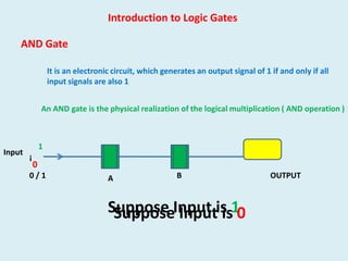
1. Introduction to Logic Gates
AND Gate
It is an electronic circuit, which generates an output signal of 1 if and only if all
input signals are also 1
An AND gate is the physical realization of the logical multiplication ( AND operation )
Input
1
i
0
0/1
A
B
Suppose Input is 10
Suppose Input is
OUTPUT
2. Block Diagram of AND Gate
A
Output
B
1
.
INPUT
1
=
OUTPUT
1
1
1
1
0
0
0
1
0
0
0
0
1
d
i
0/1
1
A
B
OUTPUT
3. Block Diagram of AND Gate
A
Output
B
1
.
INPUT
0
=
OUTPUT
1
1
1
1
0
0
0
1
0
0
0
0
0
i
0/1
0
A
B
OUTPUT
4. Block Diagram of AND Gate
A
Output
B
0
.
INPUT
1
=
OUTPUT
1
1
1
1
0
0
0
1
0
0
0
0
0
i
0/1
0
A
B
OUTPUT
5. Block Diagram of AND Gate
A
Output
B
0
.
INPUT
0
=
OUTPUT
1
1
1
1
0
0
0
1
0
0
0
0
0
i
0/1
0
A
B
OUTPUT
6. OR Gate
It is an electronic circuit,
which generates an output signal of 1, if any of the output signals is 1
It is the physical realization of logical OR
i
1
A
0/1
1
B
1
OUTPUT
7. Block Diagram of OR Gate
A
B
1
+
INPUT
1
=
OUTPUT
1
B
0
1
1
1
0
0/1
1
0
A
1
1
i
1
0
0
gg
1
OUTPUT
8. Block Diagram of OR Gate
A
B
1
+
INPUT
0
=
OUTPUT
1
B
0
1
1
1
0
0/1
1
0
A
1
1
i
1
0
0
gg
1
OUTPUT
9. Block Diagram of OR Gate
A
B
0
+
INPUT
1
=
OUTPUT
1
B
0
1
1
1
0
0/1
1
0
A
1
1
i
1
0
0
gg
1
OUTPUT
10. Block Diagram of OR Gate
A
B
0
+
INPUT
0
=
OUTPUT
1
B
0
1
1
1
0
0/1
1
0
A
1
1
i
0
0
0
gg
1
OUTPUT
11. NOT Gate
It is an electronic circuitthat generates an output signal, which is reverse of input signal
It is the physical realization of complementation operation
INPUT
OUTPUT
0
1
1
0
A
0
1
Output
Not Gate is also called inverter because it inverts the input.
13. Symbol of NAND gate
NAND Gate
Not AND Gate -
NOT + AND gate
It is a combination of NOT and AND gates
It is Complemented AND Gate
A.B
A
Output
B
Truth Table
Equation of NAND Gate
INPUT
OUTPUT
1
A↑B =
=
+
1
0
1
0
1
0
1
1
0
0
1
14. Symbol of NAND gate
NAND Gate
Not AND Gate -
NOT + AND gate
It is a combination of NOT and AND gates
It is Complemented AND Gate
A.B
A
Output
B
Truth Table
Equation of NAND Gate
INPUT
OUTPUT
1
A↑B =
=
+
1
0
1
0
1
0
1
1
0
0
1
15. Symbol of NAND gate
NAND Gate
Not AND Gate -
NOT + AND gate
It is a combination of NOT and AND gates
It is Complemented AND Gate
A.B
A
Output
B
Truth Table
Equation of NAND Gate
INPUT
OUTPUT
1
A↑B =
=
+
1
0
1
0
1
0
1
1
0
0
1
16. Symbol of NAND gate
NAND Gate
Not AND Gate -
NOT + AND gate
It is a combination of NOT and AND gates
It is Complemented AND Gate
A.B
A
Output
B
Truth Table
Equation of NAND Gate
INPUT
OUTPUT
1
A↑B =
=
+
1
0
1
0
1
0
1
1
0
0
1
17. NOR Gate
Symbol of NOR Gate
NOT – OR Gate
NOT Gate + OR Gate
A
It is complement OR gate
B
Output
A+B
A
B
Output
1+1=0
Truth Table
INPUT
Equation of NOR Gate
OUTPUT
1
A↑B =
=
.
1
0
1
0
0
0
1
0
0
0
1
18. NOR Gate
Symbol of NOR Gate
NOT – OR Gate
NOT Gate + OR Gate
A
It is complement OR gate
B
Output
A+B
A
B
Output
1+0=0
Truth Table
INPUT
Equation of NOR Gate
OUTPUT
1
A↑B =
=
.
1
0
1
0
0
0
1
0
0
0
1
19. NOR Gate
Symbol of NOR Gate
NOT – OR Gate
NOT Gate + OR Gate
A
It is complement OR gate
B
Output
A+B
A
B
Output
0+1=0
Truth Table
INPUT
Equation of NOR Gate
OUTPUT
1
A↑B =
=
.
1
0
1
0
0
0
1
0
0
0
1
20. NOR Gate
Symbol of NOR Gate
NOT – OR Gate
NOT Gate + OR Gate
A
It is complement OR gate
B
Output
A+B
A
B
Output
0+0=1
Truth Table
INPUT
Equation of NOR Gate
OUTPUT
1
A↑B =
=
.
1
0
1
0
0
0
1
0
0
0
1