SlideShare uma empresa Scribd logo
1 de 6
Baixar para ler offline
1PRODUCT DESCRIPTION
2 PARTS DESCRIPTION
OUTDOOR PASSIVE SENSOR
MS-100E
Thank you for purchasing a TAKEX product.
This switch will provide long and dependable service when properly installed.
Please read this Instruction Manual carefully for correct and effective use.
Please Note : This switch is designed to detect passing objects and to initiate a signal ; it is not a burglary-preventing device.
TAKEX is not responsible for damage or losses caused by accident, theft, Acts of God (including lightning),
abuse, misuse, abnormal usage, faulty installation of improper maintenance.
Cover Screw
Cover
Body of Unit
Terminal
Wire knockout
Wire Feed
Through
Contact
Selection
Sensor Case
Lens Holder
Sensitivity
Adjustment
Filter Masking Seal
Lens
(Attached
at Factory)
Operation LED
Tamper Switch
This sensor unit uses a passive infrared sensors to detect infrared (≒ body temprature) emitted from a
human body, which can be used as an automatic switch.
This unit is designed for wide applications such as a switch to control illumination or home automation
apparatus.
0.8∼1.5m
(2.6∼5')
3m Max
(10')
Cover screw
Lens
Filter
Lens Holder
Bottom
Top
3 PRECAUTIONS
1. Precautions on Installation
2. Other Precautions
[Vertical installation] [Horizontal installation]
●Install the unit in such a direction that people are
more likely to cross the detection zones.
◎For horizontal installation,
do not instll in a site which
is subject to rainfall.
◎Cover screw should be
downward.
●The unit should be installed as the following.
●In case of outdoor installation, adjust the lens holder
to 2°, 4°, 6°downward from horizontal.
●Do not install the unit by an air conditioning
exhaust vent.
Remove all obstructions (trees, clotheslines, etc.)
●Check the detection zones before operation.
(Unexpected objects may be detected.)
●Install in a site which avoid direct sunlight.
If not, use the filter. (See below)
●Do not install in a site
which is subject to
electrical noise or
vibration.
●Remove obstructions, including glasses, from the
detection zones.
●Avoid using the unit for primary security purpose.
(The unit is designed to detect infrared energy
variation caused by a human body.
Therefore, similar variations in conditions due to
other reasons, may cause the sensor to output a
signal as it is unable to distinguish between the
sources.)
●Insert the filter between the lens and the lens holder
when using the unit in a site which is subject to
direct sunlight.
●The filter reduces influence
of sunlight.
(This also lowers the
sensitivity.)
Check the sensitivity by a
walk test.
4
1.1m
(3.6')
1.1m
(3.6')
2.2m
(7.2')
Height
0.8∼1.5m
(2.6∼5')
1.2m
(4')
Height
0.8∼1.5m
(2.6∼5')
Zone Masking
*
*
*
Height
0.8∼1.5m
(2.6∼5')
1.2m
(4')
1.2m
(4')
0 0
0
5m
(16.5')
5m
(16.5')
20m
(66')
2m
(6.6')
0.2m(0.66')
2.7m(9')
4m(13')
64° 60°
180°
180°
30°
0.3m(1')
0.3m(1')
3m
(10')
Height
10m
(33')
10m
(33')
10m
(33')
6°
6°
6°
0.7m
(2.3')
0.7m
(2.3')
1.4m
(4.6')
11.5m(38')
64°
55°55°
180°
180°
180°
1.2m(4')
1.2m(4')
1.2m(4')
Long Range
[Max. 20m (66')]
Wide Angle
[Max. 10m (33')]
Curtain
[Max. 10m (33')]
Indoor / Outdoor
Mounting Height 0.8∼1.5m (2.6∼5')
Mounting
Position
DetectionArea(WideAngle:Setatfactory)CoverageLenssetting
CautionsonOutdoor
Mounting
Indoor
Height 3m (10')
Vertical InstallationInstallation Horizontal Installation
Curtain
[Max. 3m (10')]
Lens (Attached at Factory)Lens for Long RangeLens (Attached at Factory)
Install properly.
MS-100E can set up 4 different patterns of coverage with 2 types of lens.
Do not fail to set coverage to a lower angle than horizontal.
(2°, 4°, 6°)
Mask two upper
zones.
Do not install in a site which is
subject to direct rainfall.
●
●
●
●
Lens
Ceilling
Mount
Wall
Mount
Ceilling
Mount
Wall
Mount
±55°
6°
6°
(6°)
±90° ±90°
±30°
30°
Mark
Top
W
W
C
C
W
Mark C
Mark C
Top Top
C
C
1. Detection chart
DETECTION AREA
5 ADJUSTMENT
(1) Angle Adjustment
Sensitivity Adjustment
(1) OUTPUT CONTACT
①Sensor Case ①Coverage
②Operation LED
*
●
● Contact Selection●
②Angle Adjustment Level
(2) Zone Masking
2. Lens Setting
MASKING SEAL 9039-67
3. Angle Adjustment
[Vertical installation]
Locking edge
Lens
Lens Holder
FOR
OPERATION LED (ATTACH SEAL DOUBLE)
LENS
REPLACEMENT
VERTICAL
ADJUSTMENT
FOR
AREA
N / O
N / C
H
FACTORY SET
PIRSENS.
L
Masking
AVOID DIRECT RAINFALL ON HORIZONTAL INSTLLATION /
VERTICAL VERTICAL
HOLIZONTAL HOLIZONTAL HOLIZONTAL HOLIZONTAL
[Horizontal installation]
Holder Level
Mark
Setting Mark
Area Mark ( W, C )
±90°Variable
Downward6°
±90°Variable
Curtain
Wide Angle
Vertical Curtain
Use zone masking seal to cut unnecessary zones.
In case of curtain coverage, mask two upper
zones with seals.
Cut off locking edges of lens and adjust lens
holder to set holder level to 2°, 4°, or 6°.
●
●
This volume is for adjusting the sensitivity
of passive infrared sensor.
Adjust sensitivity when necessary according
to environment.
Usually there is no need to change the
sensitivity set at the factory.
● Output contact can be
selectable.
(N/O or N/C)
Use masking seals to mask the hole of Operation
LED.
①Adjust lens holder to set holder level to 0°.
③Refer to lens setting in chart (4. 1).
Attach appropriate lens on lens holder and,
adjust lens to fit Setting Mark to mark
W or C .
(a) Turn sensor case to sdjust the required angle.
Refer to the seal on the unit.
(b) In case of vertical installation in outdoor, adjust
lens holder to set holder level to 2°, 4°, or 6°.
②Remove lens from lens holder.
Up to 350m
(1150ft)
Up to 550m
(1800ft)
Up to 900m
(2950ft)
Up to 3400m
(11000ft)
Up to 5200m
(17000ft)
Up to 8100m
(26500ft)
6 WIRING
1. Terminal Configuration
POWER ALARM OUTPUT TAMPER
POWER
ALARM OUTPUT
TAMPER
2. Wiring distance
1. Setting for operation check
2. Operation check
3. Wire insertion
10.5 to 28V DC/30mA
(non-polarity)
Dry contact N.C./N.O. selectable
30V・0.5A max (resistive load)
Dry contact N/C
30V・2A max
(resistive load)
Read (3) PRECAUTIONS before installation.
●Break either the top or bottom knock-outs, if necessary.
Pull wire through the insertion holes.
Maximum wiring distance when two or more sets are
connected is the value above divided by number of sets.
●DC10.5∼28V (Non Polarity)
●Current Consumption 30mA MAX.
●Dry contact relay output form N.O / N.C selectable.
●Dry contact relay output N / C
7 INSTALLATION
8 OPERATION CHECK
①
Loosen the cover screw and remove cover from unit.②
Refer to (4) DETECTION AREA and adjust to the
required angle.
③
Refer to (6) WIRING and connect wires to the
terminal.
④
Supply power with cover detached and wait
approx. 1 min for warm-up period.
(1)
Check if whole system functions well.(4)
After warm-up period, operate a walk test in the
detection area to check, if the required area is
covered.
(Operation LED is activated at the time of detection.)
(2)
Readjust the sensor case or mask zones, if necessary.(3)
Secure the body of
unit to wall with
screws provided.
⑤
Refer to (8) OPERATION CHECK and check the
operation.
⑥
Refer to (5) ADJUSTMENT set up for desired
operation.
⑦
Replace the cover.⑧
…… Form N.O. / N.C.
Knockout
Insertion holes
Knockout
Knockout
CONTACT CAPACITY :
30V (AC・DC), 0.5A MAX. (resistive load)
CONTACT CAPACITY :
30V (AC・DC), 2A MAX. (resistive load)
Input Voltage
Size of Wire
DC 12V
AWG 22
(Dia. 0.65mm)
AWG 20
(Dia. 0.8mm)
AWG 18
(Dia. 1mm)
DC 24V
NOTE :
Adjust to the required angle.
Contact
9
10 SPECIFICATIONS
Model
Detection system
Coverage
Supply voltage
Current consumption
Alarm output
Tamper output
Sensitivity
adjustment
Ambient temperature
Mounting position
Operation LED
Connection
Weight
Appearance
Optional
MS-100E
Passive infrared
Vertical Installation
● Wide Angle [Max. 10m (33')]
● Curtain [Max. 10m (33')]
● Long Range [Max. 20m (66')]
Horizontal Installation
● Vertical Curtain [Max. 3m (10')]
10.5VDC to 28VDC (Non polarity)
30mA or less
Dry contact relay output Form N.C. / N.O. selectable
● Contact capacity : 30V (AC・DC), 0.5A MAX.
(Resistive load)
● Contact operation : Detection time + delay time
(Approx. 2 sec.)
Dry contact relay output N / C
● Contact capacity : 30V (AC・DC), 2A MAX.
(Resistive load)
● Approx. 30% ( L ) ---Approx. 170% ( H )
( 100% set at factory)
-4°F to +122°F (-20°C to +50°C)
Vertical Installation
● Indoor / outdoor (Height 0.8 - 1.5m)
Horizontal Installation
● Indoor (Height 3m MAX.)
Lighting at alarm
Terminals
7.7 oz (220g)
Cover : PE resin (white) Body : AES resin (White)
Pole cover (BP-11), Wall mount attachment (BW-14),
Magnetic sheet (BR-M5), Pole attachment (BP-12)
Sensor Switch
TROUBLESHOOTING
EXTERNAL DIMENSIONS
11
Symptom Possible Cause Remedy
Inactive
1. No power supply. Inadequate voltage.
2. Warm-up period.
3. Obstructions in the coverage.
4. Mis-alignment of coverage.
5. Stained cover.
1. Ensure correct and adequate supply voltage.
2. Wait 1 min. after power is supplied.
3. Remove obstructions.
4. Readjust.
5. Clean with soft cloth.
Malfunction
False signal
1. Unstable voltage.
2. Something moving or rapid temperature variation in
detection area.
3. A large electric noise source is located nearby.
4. Direct sunlight shining on the unit.
5. Detecting untargetted objects.
6. Small animals.
1. Stabilize supply voltage.
2. Remove cause or change coverage.
Turn the sensitivity adjustment down.
3. Remove the problem or replace the unit.
4. Remove the problem or replace the unit.
Readjust the coverage.
Insert the attached filter.
5. Readjust the coverage.
6. Prevent small animals from coming in or readjust unit.
1. Bad wiring connection or broken wire or short.
2. Improper terminal connection.
3. Improper unit is connected.
1. Check wiring again.
2. Check terminal connection with a tester.
3. Check connected unit.
Installed unit does not
operate, while LED is on.
If normal operation can not be restored by these means, contact either the dealer from whom you bought the unit or TAKEX directly.
※Specifications and design are subject to change without prior notice.
Analyze possible problems according to the following table.
(R1.38")
77mm
R35mm Cover screw
(2-φ0.17")
2-φ4.2mm
70mm
Knockout
Knockout
171mm(6.73")
147.5mm
76mm
(5.81")
(2.99")
(71.5mm)
(2.81")
(3.03") (2.76")
Screw hole
Limited Warranty :
TAKEX products are warranted to be free from defects in material and workmanship for 12 months from original date of shipment. Our warranty does not cover
damage or failure caused by natural disasters, abuse, misuse, abnormal usage, faulty installation, improper maintenance or any repairs other than those provided
by TAKEX. All implied warranties with respect to TAKEX, including implied warranties for merchantability and implied warranties for fitness, are limited in
duration to 12 months from original date of shipment. During the Warranty Period, TAKEX will repair or replace, at its sole option,free of charge, any defective
parts returned prepaid. Please provide the model number of the products, original date of shipment and nature of difficulty being experienced. There will be
charges rendered for product repairs made after our Warranty Period has expired.
No.05-820 1409
In Japan
Takex America Inc.
4/15 Howleys Road, Notting Hill,
VIC, 3168
Tel : +61 (03) 9544-2477
Fax : +61 (03) 9543-2342
Takenaka Engineering Co., Ltd.
83-1, Gojo-sotokan, Higashino,
Yamashina-ku, Kyoto 607-8156, Japan
Tel : 81-75-501-6651
Fax : 81-75-593-3816
http : // www. takex-eng. co. jp /
Takex America Inc.
3350, Montgomery Drive
Sant Clara, CA 95054, U.S.A.
Tel : 408-747-0100
Fax : 408-734-1100
http : // www. takex. com
Takex Europe Ltd.
Takex House, Aviary Court, Wade Road,
Basingstoke, Hampshire. RG24 8PE, U.K.
Tel : (+44) 01256-475555
Fax : (+44) 01256-466268
http : // www. takexeurope. com
In the U.S. In the U.K.In Australia

Mais conteúdo relacionado

Destaque

Destaque (6)

BAS evaluation data
BAS evaluation dataBAS evaluation data
BAS evaluation data
 
Karla tinedo la seguridad en los contratos electrónicos - informática jurídica
Karla tinedo   la seguridad en los contratos electrónicos - informática jurídicaKarla tinedo   la seguridad en los contratos electrónicos - informática jurídica
Karla tinedo la seguridad en los contratos electrónicos - informática jurídica
 
Kertas kerja makmal teknologi pendidikan - 2009
Kertas kerja    makmal teknologi pendidikan - 2009Kertas kerja    makmal teknologi pendidikan - 2009
Kertas kerja makmal teknologi pendidikan - 2009
 
How to Launch an Effective User Retention Strategy
How to Launch an Effective User Retention StrategyHow to Launch an Effective User Retention Strategy
How to Launch an Effective User Retention Strategy
 
Продуктивне навчання в_гуртку_екологічний_дизайн
Продуктивне навчання в_гуртку_екологічний_дизайнПродуктивне навчання в_гуртку_екологічний_дизайн
Продуктивне навчання в_гуртку_екологічний_дизайн
 
Reka Tisa, Petra Dilparić
Reka Tisa, Petra DilparićReka Tisa, Petra Dilparić
Reka Tisa, Petra Dilparić
 

Mais de JMAC Supply

Mais de JMAC Supply (20)

Bosch ALTV244UL Data Sheet
Bosch ALTV244UL Data SheetBosch ALTV244UL Data Sheet
Bosch ALTV244UL Data Sheet
 
Bosch AL1002WAL Data Sheet
Bosch AL1002WAL Data SheetBosch AL1002WAL Data Sheet
Bosch AL1002WAL Data Sheet
 
Bosch AIM-AEC21-CVT Data Sheet
Bosch AIM-AEC21-CVT Data SheetBosch AIM-AEC21-CVT Data Sheet
Bosch AIM-AEC21-CVT Data Sheet
 
Bosch AI1 Data Sheet
Bosch AI1 Data SheetBosch AI1 Data Sheet
Bosch AI1 Data Sheet
 
Bosch AH-24WP-R Data Sheet
Bosch AH-24WP-R Data SheetBosch AH-24WP-R Data Sheet
Bosch AH-24WP-R Data Sheet
 
Bosch AEC-8I8O-EXT Data Sheet
Bosch AEC-8I8O-EXT Data SheetBosch AEC-8I8O-EXT Data Sheet
Bosch AEC-8I8O-EXT Data Sheet
 
Bosch AE774 Data Sheet
Bosch AE774 Data SheetBosch AE774 Data Sheet
Bosch AE774 Data Sheet
 
Bosch AE203R Data Sheet
Bosch AE203R Data SheetBosch AE203R Data Sheet
Bosch AE203R Data Sheet
 
Bosch AE101 Data Sheet
Bosch AE101 Data SheetBosch AE101 Data Sheet
Bosch AE101 Data Sheet
 
Bosch AE4 Data Sheet
Bosch AE4 Data SheetBosch AE4 Data Sheet
Bosch AE4 Data Sheet
 
Bosch AE1 Data Sheet
Bosch AE1 Data SheetBosch AE1 Data Sheet
Bosch AE1 Data Sheet
 
Bosch ACD-IC16K37-50 Data Sheet
Bosch ACD-IC16K37-50 Data SheetBosch ACD-IC16K37-50 Data Sheet
Bosch ACD-IC16K37-50 Data Sheet
 
Bosch ACD-IC2K37-50 Data Sheet
Bosch ACD-IC2K37-50 Data SheetBosch ACD-IC2K37-50 Data Sheet
Bosch ACD-IC2K37-50 Data Sheet
 
Bosch ACA-IC2K26-10 Data Sheet
Bosch ACA-IC2K26-10 Data SheetBosch ACA-IC2K26-10 Data Sheet
Bosch ACA-IC2K26-10 Data Sheet
 
Bosch 9208B Data Sheet
Bosch 9208B Data SheetBosch 9208B Data Sheet
Bosch 9208B Data Sheet
 
Bosch 7110XC Data Sheet
Bosch 7110XC Data SheetBosch 7110XC Data Sheet
Bosch 7110XC Data Sheet
 
Samsung Techwin SNB-1000 Data Sheet
Samsung Techwin SNB-1000 Data SheetSamsung Techwin SNB-1000 Data Sheet
Samsung Techwin SNB-1000 Data Sheet
 
Samsung Techwin SMT-4031 Data Sheet
Samsung Techwin SMT-4031 Data SheetSamsung Techwin SMT-4031 Data Sheet
Samsung Techwin SMT-4031 Data Sheet
 
Samsung Techwin SMT-4023 Data Sheet
Samsung Techwin SMT-4023 Data SheetSamsung Techwin SMT-4023 Data Sheet
Samsung Techwin SMT-4023 Data Sheet
 
Samsung Techwin SMT-3232 Data Sheet
Samsung Techwin SMT-3232 Data SheetSamsung Techwin SMT-3232 Data Sheet
Samsung Techwin SMT-3232 Data Sheet
 

Último

Cloud Frontiers: A Deep Dive into Serverless Spatial Data and FME
Cloud Frontiers:  A Deep Dive into Serverless Spatial Data and FMECloud Frontiers:  A Deep Dive into Serverless Spatial Data and FME
Cloud Frontiers: A Deep Dive into Serverless Spatial Data and FME
Safe Software
 
Why Teams call analytics are critical to your entire business
Why Teams call analytics are critical to your entire businessWhy Teams call analytics are critical to your entire business
Why Teams call analytics are critical to your entire business
panagenda
 
+971581248768>> SAFE AND ORIGINAL ABORTION PILLS FOR SALE IN DUBAI AND ABUDHA...
+971581248768>> SAFE AND ORIGINAL ABORTION PILLS FOR SALE IN DUBAI AND ABUDHA...+971581248768>> SAFE AND ORIGINAL ABORTION PILLS FOR SALE IN DUBAI AND ABUDHA...
+971581248768>> SAFE AND ORIGINAL ABORTION PILLS FOR SALE IN DUBAI AND ABUDHA...
?#DUbAI#??##{{(☎️+971_581248768%)**%*]'#abortion pills for sale in dubai@
 
Architecting Cloud Native Applications
Architecting Cloud Native ApplicationsArchitecting Cloud Native Applications
Architecting Cloud Native Applications
WSO2
 

Último (20)

Cloud Frontiers: A Deep Dive into Serverless Spatial Data and FME
Cloud Frontiers:  A Deep Dive into Serverless Spatial Data and FMECloud Frontiers:  A Deep Dive into Serverless Spatial Data and FME
Cloud Frontiers: A Deep Dive into Serverless Spatial Data and FME
 
Apidays New York 2024 - Scaling API-first by Ian Reasor and Radu Cotescu, Adobe
Apidays New York 2024 - Scaling API-first by Ian Reasor and Radu Cotescu, AdobeApidays New York 2024 - Scaling API-first by Ian Reasor and Radu Cotescu, Adobe
Apidays New York 2024 - Scaling API-first by Ian Reasor and Radu Cotescu, Adobe
 
TrustArc Webinar - Unlock the Power of AI-Driven Data Discovery
TrustArc Webinar - Unlock the Power of AI-Driven Data DiscoveryTrustArc Webinar - Unlock the Power of AI-Driven Data Discovery
TrustArc Webinar - Unlock the Power of AI-Driven Data Discovery
 
Navi Mumbai Call Girls 🥰 8617370543 Service Offer VIP Hot Model
Navi Mumbai Call Girls 🥰 8617370543 Service Offer VIP Hot ModelNavi Mumbai Call Girls 🥰 8617370543 Service Offer VIP Hot Model
Navi Mumbai Call Girls 🥰 8617370543 Service Offer VIP Hot Model
 
Why Teams call analytics are critical to your entire business
Why Teams call analytics are critical to your entire businessWhy Teams call analytics are critical to your entire business
Why Teams call analytics are critical to your entire business
 
Apidays New York 2024 - The Good, the Bad and the Governed by David O'Neill, ...
Apidays New York 2024 - The Good, the Bad and the Governed by David O'Neill, ...Apidays New York 2024 - The Good, the Bad and the Governed by David O'Neill, ...
Apidays New York 2024 - The Good, the Bad and the Governed by David O'Neill, ...
 
Emergent Methods: Multi-lingual narrative tracking in the news - real-time ex...
Emergent Methods: Multi-lingual narrative tracking in the news - real-time ex...Emergent Methods: Multi-lingual narrative tracking in the news - real-time ex...
Emergent Methods: Multi-lingual narrative tracking in the news - real-time ex...
 
Apidays Singapore 2024 - Modernizing Securities Finance by Madhu Subbu
Apidays Singapore 2024 - Modernizing Securities Finance by Madhu SubbuApidays Singapore 2024 - Modernizing Securities Finance by Madhu Subbu
Apidays Singapore 2024 - Modernizing Securities Finance by Madhu Subbu
 
ICT role in 21st century education and its challenges
ICT role in 21st century education and its challengesICT role in 21st century education and its challenges
ICT role in 21st century education and its challenges
 
Web Form Automation for Bonterra Impact Management (fka Social Solutions Apri...
Web Form Automation for Bonterra Impact Management (fka Social Solutions Apri...Web Form Automation for Bonterra Impact Management (fka Social Solutions Apri...
Web Form Automation for Bonterra Impact Management (fka Social Solutions Apri...
 
DBX First Quarter 2024 Investor Presentation
DBX First Quarter 2024 Investor PresentationDBX First Quarter 2024 Investor Presentation
DBX First Quarter 2024 Investor Presentation
 
Connector Corner: Accelerate revenue generation using UiPath API-centric busi...
Connector Corner: Accelerate revenue generation using UiPath API-centric busi...Connector Corner: Accelerate revenue generation using UiPath API-centric busi...
Connector Corner: Accelerate revenue generation using UiPath API-centric busi...
 
+971581248768>> SAFE AND ORIGINAL ABORTION PILLS FOR SALE IN DUBAI AND ABUDHA...
+971581248768>> SAFE AND ORIGINAL ABORTION PILLS FOR SALE IN DUBAI AND ABUDHA...+971581248768>> SAFE AND ORIGINAL ABORTION PILLS FOR SALE IN DUBAI AND ABUDHA...
+971581248768>> SAFE AND ORIGINAL ABORTION PILLS FOR SALE IN DUBAI AND ABUDHA...
 
Artificial Intelligence Chap.5 : Uncertainty
Artificial Intelligence Chap.5 : UncertaintyArtificial Intelligence Chap.5 : Uncertainty
Artificial Intelligence Chap.5 : Uncertainty
 
MINDCTI Revenue Release Quarter One 2024
MINDCTI Revenue Release Quarter One 2024MINDCTI Revenue Release Quarter One 2024
MINDCTI Revenue Release Quarter One 2024
 
How to Troubleshoot Apps for the Modern Connected Worker
How to Troubleshoot Apps for the Modern Connected WorkerHow to Troubleshoot Apps for the Modern Connected Worker
How to Troubleshoot Apps for the Modern Connected Worker
 
A Year of the Servo Reboot: Where Are We Now?
A Year of the Servo Reboot: Where Are We Now?A Year of the Servo Reboot: Where Are We Now?
A Year of the Servo Reboot: Where Are We Now?
 
MS Copilot expands with MS Graph connectors
MS Copilot expands with MS Graph connectorsMS Copilot expands with MS Graph connectors
MS Copilot expands with MS Graph connectors
 
Data Cloud, More than a CDP by Matt Robison
Data Cloud, More than a CDP by Matt RobisonData Cloud, More than a CDP by Matt Robison
Data Cloud, More than a CDP by Matt Robison
 
Architecting Cloud Native Applications
Architecting Cloud Native ApplicationsArchitecting Cloud Native Applications
Architecting Cloud Native Applications
 

Takex MS-100E Instruction Manual

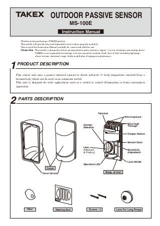
  • 1. 1PRODUCT DESCRIPTION 2 PARTS DESCRIPTION OUTDOOR PASSIVE SENSOR MS-100E Thank you for purchasing a TAKEX product. This switch will provide long and dependable service when properly installed. Please read this Instruction Manual carefully for correct and effective use. Please Note : This switch is designed to detect passing objects and to initiate a signal ; it is not a burglary-preventing device. TAKEX is not responsible for damage or losses caused by accident, theft, Acts of God (including lightning), abuse, misuse, abnormal usage, faulty installation of improper maintenance. Cover Screw Cover Body of Unit Terminal Wire knockout Wire Feed Through Contact Selection Sensor Case Lens Holder Sensitivity Adjustment Filter Masking Seal Lens (Attached at Factory) Operation LED Tamper Switch This sensor unit uses a passive infrared sensors to detect infrared (≒ body temprature) emitted from a human body, which can be used as an automatic switch. This unit is designed for wide applications such as a switch to control illumination or home automation apparatus.
  • 2. 0.8∼1.5m (2.6∼5') 3m Max (10') Cover screw Lens Filter Lens Holder Bottom Top 3 PRECAUTIONS 1. Precautions on Installation 2. Other Precautions [Vertical installation] [Horizontal installation] ●Install the unit in such a direction that people are more likely to cross the detection zones. ◎For horizontal installation, do not instll in a site which is subject to rainfall. ◎Cover screw should be downward. ●The unit should be installed as the following. ●In case of outdoor installation, adjust the lens holder to 2°, 4°, 6°downward from horizontal. ●Do not install the unit by an air conditioning exhaust vent. Remove all obstructions (trees, clotheslines, etc.) ●Check the detection zones before operation. (Unexpected objects may be detected.) ●Install in a site which avoid direct sunlight. If not, use the filter. (See below) ●Do not install in a site which is subject to electrical noise or vibration. ●Remove obstructions, including glasses, from the detection zones. ●Avoid using the unit for primary security purpose. (The unit is designed to detect infrared energy variation caused by a human body. Therefore, similar variations in conditions due to other reasons, may cause the sensor to output a signal as it is unable to distinguish between the sources.) ●Insert the filter between the lens and the lens holder when using the unit in a site which is subject to direct sunlight. ●The filter reduces influence of sunlight. (This also lowers the sensitivity.) Check the sensitivity by a walk test.
  • 3. 4 1.1m (3.6') 1.1m (3.6') 2.2m (7.2') Height 0.8∼1.5m (2.6∼5') 1.2m (4') Height 0.8∼1.5m (2.6∼5') Zone Masking * * * Height 0.8∼1.5m (2.6∼5') 1.2m (4') 1.2m (4') 0 0 0 5m (16.5') 5m (16.5') 20m (66') 2m (6.6') 0.2m(0.66') 2.7m(9') 4m(13') 64° 60° 180° 180° 30° 0.3m(1') 0.3m(1') 3m (10') Height 10m (33') 10m (33') 10m (33') 6° 6° 6° 0.7m (2.3') 0.7m (2.3') 1.4m (4.6') 11.5m(38') 64° 55°55° 180° 180° 180° 1.2m(4') 1.2m(4') 1.2m(4') Long Range [Max. 20m (66')] Wide Angle [Max. 10m (33')] Curtain [Max. 10m (33')] Indoor / Outdoor Mounting Height 0.8∼1.5m (2.6∼5') Mounting Position DetectionArea(WideAngle:Setatfactory)CoverageLenssetting CautionsonOutdoor Mounting Indoor Height 3m (10') Vertical InstallationInstallation Horizontal Installation Curtain [Max. 3m (10')] Lens (Attached at Factory)Lens for Long RangeLens (Attached at Factory) Install properly. MS-100E can set up 4 different patterns of coverage with 2 types of lens. Do not fail to set coverage to a lower angle than horizontal. (2°, 4°, 6°) Mask two upper zones. Do not install in a site which is subject to direct rainfall. ● ● ● ● Lens Ceilling Mount Wall Mount Ceilling Mount Wall Mount ±55° 6° 6° (6°) ±90° ±90° ±30° 30° Mark Top W W C C W Mark C Mark C Top Top C C 1. Detection chart DETECTION AREA
  • 4. 5 ADJUSTMENT (1) Angle Adjustment Sensitivity Adjustment (1) OUTPUT CONTACT ①Sensor Case ①Coverage ②Operation LED * ● ● Contact Selection● ②Angle Adjustment Level (2) Zone Masking 2. Lens Setting MASKING SEAL 9039-67 3. Angle Adjustment [Vertical installation] Locking edge Lens Lens Holder FOR OPERATION LED (ATTACH SEAL DOUBLE) LENS REPLACEMENT VERTICAL ADJUSTMENT FOR AREA N / O N / C H FACTORY SET PIRSENS. L Masking AVOID DIRECT RAINFALL ON HORIZONTAL INSTLLATION / VERTICAL VERTICAL HOLIZONTAL HOLIZONTAL HOLIZONTAL HOLIZONTAL [Horizontal installation] Holder Level Mark Setting Mark Area Mark ( W, C ) ±90°Variable Downward6° ±90°Variable Curtain Wide Angle Vertical Curtain Use zone masking seal to cut unnecessary zones. In case of curtain coverage, mask two upper zones with seals. Cut off locking edges of lens and adjust lens holder to set holder level to 2°, 4°, or 6°. ● ● This volume is for adjusting the sensitivity of passive infrared sensor. Adjust sensitivity when necessary according to environment. Usually there is no need to change the sensitivity set at the factory. ● Output contact can be selectable. (N/O or N/C) Use masking seals to mask the hole of Operation LED. ①Adjust lens holder to set holder level to 0°. ③Refer to lens setting in chart (4. 1). Attach appropriate lens on lens holder and, adjust lens to fit Setting Mark to mark W or C . (a) Turn sensor case to sdjust the required angle. Refer to the seal on the unit. (b) In case of vertical installation in outdoor, adjust lens holder to set holder level to 2°, 4°, or 6°. ②Remove lens from lens holder.
  • 5. Up to 350m (1150ft) Up to 550m (1800ft) Up to 900m (2950ft) Up to 3400m (11000ft) Up to 5200m (17000ft) Up to 8100m (26500ft) 6 WIRING 1. Terminal Configuration POWER ALARM OUTPUT TAMPER POWER ALARM OUTPUT TAMPER 2. Wiring distance 1. Setting for operation check 2. Operation check 3. Wire insertion 10.5 to 28V DC/30mA (non-polarity) Dry contact N.C./N.O. selectable 30V・0.5A max (resistive load) Dry contact N/C 30V・2A max (resistive load) Read (3) PRECAUTIONS before installation. ●Break either the top or bottom knock-outs, if necessary. Pull wire through the insertion holes. Maximum wiring distance when two or more sets are connected is the value above divided by number of sets. ●DC10.5∼28V (Non Polarity) ●Current Consumption 30mA MAX. ●Dry contact relay output form N.O / N.C selectable. ●Dry contact relay output N / C 7 INSTALLATION 8 OPERATION CHECK ① Loosen the cover screw and remove cover from unit.② Refer to (4) DETECTION AREA and adjust to the required angle. ③ Refer to (6) WIRING and connect wires to the terminal. ④ Supply power with cover detached and wait approx. 1 min for warm-up period. (1) Check if whole system functions well.(4) After warm-up period, operate a walk test in the detection area to check, if the required area is covered. (Operation LED is activated at the time of detection.) (2) Readjust the sensor case or mask zones, if necessary.(3) Secure the body of unit to wall with screws provided. ⑤ Refer to (8) OPERATION CHECK and check the operation. ⑥ Refer to (5) ADJUSTMENT set up for desired operation. ⑦ Replace the cover.⑧ …… Form N.O. / N.C. Knockout Insertion holes Knockout Knockout CONTACT CAPACITY : 30V (AC・DC), 0.5A MAX. (resistive load) CONTACT CAPACITY : 30V (AC・DC), 2A MAX. (resistive load) Input Voltage Size of Wire DC 12V AWG 22 (Dia. 0.65mm) AWG 20 (Dia. 0.8mm) AWG 18 (Dia. 1mm) DC 24V NOTE : Adjust to the required angle. Contact
  • 6. 9 10 SPECIFICATIONS Model Detection system Coverage Supply voltage Current consumption Alarm output Tamper output Sensitivity adjustment Ambient temperature Mounting position Operation LED Connection Weight Appearance Optional MS-100E Passive infrared Vertical Installation ● Wide Angle [Max. 10m (33')] ● Curtain [Max. 10m (33')] ● Long Range [Max. 20m (66')] Horizontal Installation ● Vertical Curtain [Max. 3m (10')] 10.5VDC to 28VDC (Non polarity) 30mA or less Dry contact relay output Form N.C. / N.O. selectable ● Contact capacity : 30V (AC・DC), 0.5A MAX. (Resistive load) ● Contact operation : Detection time + delay time (Approx. 2 sec.) Dry contact relay output N / C ● Contact capacity : 30V (AC・DC), 2A MAX. (Resistive load) ● Approx. 30% ( L ) ---Approx. 170% ( H ) ( 100% set at factory) -4°F to +122°F (-20°C to +50°C) Vertical Installation ● Indoor / outdoor (Height 0.8 - 1.5m) Horizontal Installation ● Indoor (Height 3m MAX.) Lighting at alarm Terminals 7.7 oz (220g) Cover : PE resin (white) Body : AES resin (White) Pole cover (BP-11), Wall mount attachment (BW-14), Magnetic sheet (BR-M5), Pole attachment (BP-12) Sensor Switch TROUBLESHOOTING EXTERNAL DIMENSIONS 11 Symptom Possible Cause Remedy Inactive 1. No power supply. Inadequate voltage. 2. Warm-up period. 3. Obstructions in the coverage. 4. Mis-alignment of coverage. 5. Stained cover. 1. Ensure correct and adequate supply voltage. 2. Wait 1 min. after power is supplied. 3. Remove obstructions. 4. Readjust. 5. Clean with soft cloth. Malfunction False signal 1. Unstable voltage. 2. Something moving or rapid temperature variation in detection area. 3. A large electric noise source is located nearby. 4. Direct sunlight shining on the unit. 5. Detecting untargetted objects. 6. Small animals. 1. Stabilize supply voltage. 2. Remove cause or change coverage. Turn the sensitivity adjustment down. 3. Remove the problem or replace the unit. 4. Remove the problem or replace the unit. Readjust the coverage. Insert the attached filter. 5. Readjust the coverage. 6. Prevent small animals from coming in or readjust unit. 1. Bad wiring connection or broken wire or short. 2. Improper terminal connection. 3. Improper unit is connected. 1. Check wiring again. 2. Check terminal connection with a tester. 3. Check connected unit. Installed unit does not operate, while LED is on. If normal operation can not be restored by these means, contact either the dealer from whom you bought the unit or TAKEX directly. ※Specifications and design are subject to change without prior notice. Analyze possible problems according to the following table. (R1.38") 77mm R35mm Cover screw (2-φ0.17") 2-φ4.2mm 70mm Knockout Knockout 171mm(6.73") 147.5mm 76mm (5.81") (2.99") (71.5mm) (2.81") (3.03") (2.76") Screw hole Limited Warranty : TAKEX products are warranted to be free from defects in material and workmanship for 12 months from original date of shipment. Our warranty does not cover damage or failure caused by natural disasters, abuse, misuse, abnormal usage, faulty installation, improper maintenance or any repairs other than those provided by TAKEX. All implied warranties with respect to TAKEX, including implied warranties for merchantability and implied warranties for fitness, are limited in duration to 12 months from original date of shipment. During the Warranty Period, TAKEX will repair or replace, at its sole option,free of charge, any defective parts returned prepaid. Please provide the model number of the products, original date of shipment and nature of difficulty being experienced. There will be charges rendered for product repairs made after our Warranty Period has expired. No.05-820 1409 In Japan Takex America Inc. 4/15 Howleys Road, Notting Hill, VIC, 3168 Tel : +61 (03) 9544-2477 Fax : +61 (03) 9543-2342 Takenaka Engineering Co., Ltd. 83-1, Gojo-sotokan, Higashino, Yamashina-ku, Kyoto 607-8156, Japan Tel : 81-75-501-6651 Fax : 81-75-593-3816 http : // www. takex-eng. co. jp / Takex America Inc. 3350, Montgomery Drive Sant Clara, CA 95054, U.S.A. Tel : 408-747-0100 Fax : 408-734-1100 http : // www. takex. com Takex Europe Ltd. Takex House, Aviary Court, Wade Road, Basingstoke, Hampshire. RG24 8PE, U.K. Tel : (+44) 01256-475555 Fax : (+44) 01256-466268 http : // www. takexeurope. com In the U.S. In the U.K.In Australia