FS-2000E Flame Sensor Instruction Manual
•
0 likes•359 views

This 3 sentence summary provides the key details about the flame sensor instruction manual: The instruction manual describes how to install and operate the FS-2000E flame sensor, which detects ultraviolet rays from flames to initiate an alarm. The sensor has adjustable detection sensitivity and timer settings. It connects to an alarm system and provides alarm and tamper contacts for integration with control panels.

Recommended
Recommended
More Related Content
What's hot
What's hot (19)
Similar to FS-2000E Flame Sensor Instruction Manual
Similar to FS-2000E Flame Sensor Instruction Manual (20)
More from JMAC Supply
More from JMAC Supply (20)
Recently uploaded
Recently uploaded (20)
FS-2000E Flame Sensor Instruction Manual
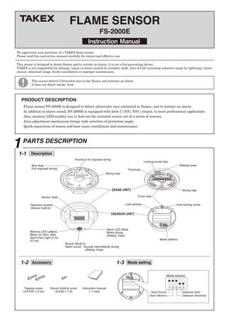
- 1. Instruction Manual FS-2000E FLAME SENSOR Flame sensor FS-2000E is designed to detect ultraviolet rays contained in flames, and to initiate an alarm. In addition to alarm sound, FS-2000E is equipped with form C (N/C, N/O.) output, to meet professional application. Also, memory LED enables you to find out the initiated sensor out of a series of sensors. Area adjustment mechanism brings wide selection of protection angle. Quick separation of sensor and base eases installation and maintenance. We appreciate your purchase of a TAKEX flame sensor. Please read this instruction manual carefully for correct and effective use. This sensor is designed to detect flames and to initiate an alarm, it is not a fire-preventing device. TAKEX is not responsible for damage, injury or losses caused by accident, theft, Acts of God (including inductive surge by lightning), abuse, misuse, abnormal usage, faulty installation or improper maintenance. 1PARTS DESCRIPTION PRODUCT DESCRIPTION Wire lead (For exposed wiring) Detection window (Sensor built-in) Memory LED (yellow) Blinks for 3min. after alarm then Light on for 47 min. Wiring hole Wiring hole Mode selector Area locking screw Front mark Lock window Buzzer (Built-in) Alarm sound : Sounds intermittently during offdelay 10sec. Sensor head Terminals Locking screw hole Release lever Knockout for exposed wiring 【SENSOR UNIT】 【BASE UNIT】 1-1 Description This sensor detects Ultraviolet rays in the flames and initiates an alarm. It does not detect smoke, heat. 1-2 Accessory 1-3 Mode setting Mode selector 1 2 3 4 5 Detection Sensitivity Alarm Sound Alarm Memory Detection timer Alarm LED (Red) Blinks during offdelay 10sec. Tapping screw (φ4×25) × 2 pcs Sensor locking screw (φ3×6) × 1 pc Instruction manual × 1 copy
- 2. Product classification Others Objects to be detected 2 ATTENTION 3DO'S AND DON'T'S ● ●● This sensor is designed to detect ultraviolet rays contained in flames, and to issue a signal. This unit is neither fire detector nor heat detector nor smoke detector. TAKEX is not responsible for damage, injury or losses by fire, accident, calamity, Acts of God (including inductive surge by lightning), abuse, misuse, abnormal usage, faulty installation or improper maintenance. ◎ According to the detection area chart and operation check, decide installtion place not to form the death angle. ◎ Do not install in the following places. ●When an strong impact is given to the sensor, it may cause damage, malfunction or less performance. Do not handle in a rough manner. ●Intense flames such like gas explosion's may damage the sensor, instead of the detection. This sensor detects ultraviolet rays contained in flames. Therefore, this sensor may detect something including ultraviolet rays but not in flame. Besides, this sensor does not detect the burning object which is not flaming. Do not install in a site which is subject to direct or reflecting sunlight and rain. (This sensor is for indoor use only) Do not install in high humid place such like bathroom. Do not install in a site where fire (flame) is usually used such like kitchen. Do not install in front of the object to intercept light. (including glass and trans- parent resin etc.) ●Do not install in a site where the temperature falls less than +14°F (-10°C) or rises more than +140°F (+60°C). ●Do not give an impact to sensor. it may cause damage, malfunction and less performance to the sensor. ●Do not put water to the sensor, or leave the sensor in humid place. It may cause malfunction. ●This sensor's alarm output is 2 sec. offdelay, and alarm sound / LED is 10 sec. offdelay action. By detecting a flame, the alarm will be initiated after the set time of timer passed. The alarm action continues during the fire, and stops 2 sec. and 10 sec. later each after the extinction. (Alarm sound : intermittently LED : continous) *when alarm sound is "OFF", it does not sound. Possible cause of false alarm Do not install the sensor nearby the followings. Flames which can not be detected. ●Halogen lamp ●Electric discharging lamp such like mercury lamp ●Electric sterilizer lamp ●Spark of welding ●Electric spark (caused by motor, pantograph) ●Sunlight ●Electric discharge of thunderbolt ●High electric field ●All the objects which emanates ultraviolet rays ●Flames through the glass or transparent resin ●Lighting portion of cigarette ●Burning charcoal or briquet ●Electric stove ●Burnig object without flames ●
- 3. 4321 765 COM N.C. N.O. Locate the installation site. (Ref : 3, DO'S AND DON'T'S and 7, DETECTION AREA) Slide the release lever to detach the sensor unit. ※To make the exposed wiring, break the knockout and insert wires into the wire lead. ※Sensor head can be adjusted ahead with 4 steps. (Ref : 7, Detection area) ●When sensor unit is detached, wrap it in palm and slide release lever. ●To lock sensor unit, insert sensor locking screw into locking screw hole and tighten it. Fix the base with the screws included. (Ref : Base installation described later) Terminal arrangement Basic connection 【Allowable wiring distance between sensor and power source】 10 to 30VDC (non-polarity) Stand-by : 25mA Alarm : 75mA Max. (buzzer : ON) 40mA Max. (buzzer : OFF) Power Sensor 1 Sensor 2 Signal input (N.C.) Control panel ① ② Connect wire to terminals of the base. (Ref : 4, WIRING) Make the set-up of detection timer, alarm sound and alarm memory. (Ref : 6-(2) Function setting) Attach the sensor unit to base unit. Check operation and area. ④ Detach sensor unit, and turn Area locking screw to right and fix sensor head tightly. All the inside of lock window have to be turned into black. ⑧ ⑤ ⑥ ⑦ Attach sensor unit on base unit.⑨ ③ 4 WIRING 5 INSTALLATION [2 units connection in series (N.C.)] Power Dry contact relay output Form C Action : Offdelay (detection time + 2 sec.) Capacity : 30V (AC/DC) 0.3A or less (protective resistance 3.3 ohms) Alarm output Dry contact output Form B (N.C.) Action : Open when sensor unit is detached Capacity : 30V (AC/DC) 0.25A or less Tamper (1) Turn front marks of base unit and sensor unit point same directions. (2) Insert sensor unit into base unit. (3) Push sensor unit until release lever is locked. 1) The maximum wire length, when two or more units are connected, is the above distance divided by the number of units. 2) The protection circuit can be wired to a distance of 3,280 ft (1,000m) with AWG 22 (0.65mm dia.) wire. ① ② ③ ④ ① ② ③ ④ + − ・ ・ { Size of wire used AWG 22 (Dia. 0.65mm) AWG 20 (Dia. 0.80mm) AWG 18 (Dia. 1.00mm) Distance at 12VDC 490 ft. (150m) 820 ft. (250m) 1,230 ft. (375m) Area locking screw Sensor head Lock window Sensor locking screw ( ( Note
- 4. Alarm (Basic action) Alarm sound (buzzer) (1) Operation (2) Mode setting Alarm memory 6 OPERATION AND FUNCTION SET ON OFF AUTO (ON) OFF Application and installation ●For the quick detection of the flame of lighter / match at no smoking zone. ●When above setting is not stable. ●For the detection of the fire at smoking zone ●At the window etc. which is subject to reflection of sunlights. SET The following setting is about detection performance. Detection sensitivity is selectable STD or L. (STD: Standard setting: Same sensitivity as previous model) Detection Sensitivity SET Timer 0.2 sec 1sec 6 sec 30 sec (Factory set : 0.2 sec) Detection timer SET L (50%) SET STD (100%) 4 5 Mode selector 1 2 3 4 5 Detection Sensitivity Alarm Sound Alarm Memory Detection timer 1 2 (Factory set : ON) (Factory set : AUTO) (Factory set : STD) 3 This product alarms only by detecting the flame continuing for the set time of detection timer. (0.2sec., 1sec., 6sec., 30sec.) When the flame continues further, the above alarm actions are also continued for the meantime. 2sec. after the flame goes out, alarm output stops, and 10sec. after, alarm sound and LED stop (off delay). Then sensor goes back to armed mode. FS-2000E is equipped with 4 functions which can be used according to the application or environment. Mode setting will be done by mode selector (dip switch) in accordance with mode setting chart on the back side of sensor unit. Installation hole approx. 5mm Marking Installation hole This product is equipped with installation holes (pitch 3.29" or 83.5mm) to make installation easy and the sensor's direction adjustable. Buzzer : Sounds intermittently every 0.2sec. LED : Lights on Alarm output : Continuous To reset the sensor LED which is blinking or lighting on, Detach sensor unit from base unit and attach it again, or put off power and on again. (Power on reset) When the ultraviolet rays of a flame is weak (it is related to size of flame and distance to sensor), alarm initiation may be delayed beyond the set time. The ultraviolet rays are not visible, and may be detected from unexpected object. When the sensor's operation is not stable (it detects something but not a flame) and its cause can not be identified, set detection time longer by one step and see the course. Buzzer can be off by mode selector No.1, when external output is used. When 2 or more sensor are connected on 1 loop, which sensor is initiated can be monitored by Memory LED (yellow) for 50 min. after alarm output. Memory LED will be off automatically after 3 min. of blinking and 47 min. of lighting on. In case that the sensor initiates alarm again while its memory LED is lighting, LED continues to light on for further 47 min. after that. (re-trigger action) [Installation of base] × × Place the base on the site and mark × on 2 points 180°apart. Thrust the 2 pcs. of tapping screws (accessory) leaving 5mm exposed from the surface. Adjust the sensor's direction by turning the base. (adjustment range 25°) (4) Tighten the screws. ● Installation hole (1) (2) (3) ※ ※ ( ( This unit detects ultraviolet rays in a flame and issues a signal. In the semi-outdoors, there are many objects which generate ultraviolet rays and because there are no walls or windows in open area, there is a much higher possibil- ity for the unit to detect those objects, in comparison with indoor installations. The detection performance should be set using the dip switches according to the circumstances of the installa- tion site. When the performance of the installed sensor is unstable and the cause cannotbe indentified, select Sensitivity "L" and detection time one step longer than current setting. *Detection distance on "L" setting is 50% shorter than that on "STD" setting. *If the operation is unstable on "STD", switch to "L". *When installed semi-outdoor, "L" setting is recommended. An alarm output occurs when the flame continues for set time of detection timer or longer.
- 5. 1. Turn power on. 2. Ignite a lighter etc. within detection area for more than the set time. 3. After the set time, an alarm output is issued, buzzer sounds intermittently and LED blinks. (Alarm action) 4. 2 sec. after the flame goes off, alarm output ends. 10sec. after the flame goes off, other alarm actions ends. (Check the alarm output by connecting a device such like bell / siren.) Do not use a lighter in no fire zone because it is dangerous. In such case, operation test have to be done in other place with sensor only. ●Detection area spreads out in front of the sensor at approx. 120°conically. Area locking screw have to be turned with a big cross driver until the inside of Lock window changes to complete black (FIXED : turn to right) or white (LOOSENED : turn to left). *Sensor installation surface can be covered by the most forward area setting. After the adjustment, detach the sensor unit. Fix the sensor head by turning Area locking screw to right, and attach it again. ●When improper area setting is found out by operation check, adjust area setting. ●The size of detection area is in proportion to the size of flame and the time of flaming. The bigger flame becomes or the longer flame continues, the bigger detection area becomes. When small flame such like lighter's is the object to be detected, confirm detection area. Detection area Approx. 120° 30°variable 10' (3m) 10' (3m) 20' (6m) 20' (6m) 30' (9m) 30' (9m) 33' (10m) 33' (10m)30°variable4 steps 7 DETECTION AREA 9 TROUBLESHOOTING 8 OPERATION CHECK 20' (6m) 23' (7m) 20' (6m) 23' (7m) 23' (7m) 20' (6m) 23' (7m) 20' (6m) 10' (3m) 10' (3m) 10' (3m) 10' (3m) Solve possible problems according to the following table . If normal operations can not be restored by these corrective actios, contact either the dealer from whom you bought the unit or TAKEX. Trouble Completely inactive Sometimes inactive Activated without flame The alarm LED and buzzer works but the connected devices are inactive Check ●No power supply (Broken wire or improper wire) ●Low voltage (When power supply wired) ●Sensor inside is wet by condensation etc. ●Interrupting rays objects in front of detection area (Glass, transparent resin are interrupting rays objects) ●Improper area setting ●Low voltage ●Detection window is soiled with dust ●Large electrical noise source such as a redio station or high-voltage wire nearby ●Sensor inside is wet by condensation etc. ●Unexpected ultraviolet rays nearby (Ref : 2, ATTENTION) ●Poor contact output connection or broken wire ●The connected unit's trouble ●Relocate the sensor to appropriate position ●Correct power supply ●Remove the dust and soil ●Relocate the sensor ●Dry out sensor inside, and remove the cause of wet ●Remove the origin of the ultraviolet rays, interrupt ultraviolet rays, or relocate the sensor ●Check the wiring or connection ●Check the connected unit ●Correct power supply or replace broken wire ●Dry out sensor inside, and remove the cause of the wet ●Remove the interrupting rays object Corrective action Side view : Ceiling / wall mount To be fixed To be loosened Area locking screw Lock window Front view : Ceiling mount Top view : Wall mount Condition of detection area Detection timer : 0.2sec. Origin of flame : Gas lighter Size of flame : Approx. 2.75" (7cm) ● 固 定 →← →← 1. DETECTION AREA 2. AREA ADJUSTMENT LOOSENED FIXED Lock window Lock windowLock window 〈Adjustment range〉 Horizontal 25°………………By base unit Vertical 30°(4 steps) ………By sensor head sensor head
- 6. 11EXTERNAL DIMENSIONS 10 SPECIFICATIONS ■OPTION ◎Ceiling/wall mount attachment (variable attachment) 〔BCW-401〕 φ4.72" (φ120mm) φ3.88" (φ98.5mm) φ3.29" (φ83.5mm) φ0.35" (φ9mm) 2.63" (66.7mm) 5-φ0.17" (5-φ4.2mm) R0.59" (R15mm) 35° 30° 35° 35° 35° 0.17"(4.2mm) Sensor unit Sensor head Variable Release lever Buzzer (built in) Locking screw hole Alarm LED (Red) Memory LED (Yellow) Detection window Wiring hole MOUNT & WIRING HOLE Base unit 1.58"(40mm) 1.34" (34mm) 0.41" (10.5mm) 0.31"(8mm) Product name Model No. Detection system Detection area Sensitivity adjustment Power supply Power consumption Alarm output Alarm memory LED Alarm sound (buzzer) Tamper output Wiring Ambient temp. renge Installation Weight External dimensions Appearance Accessories Option FLAME SENSOR FS-2000E Ultraviolet rays detection (Detected wave length 185 to 260nm) Distance Angle Adjustment range Detection Sensitivity (STD[100%] ,L[50%]) Detection timer 4 steps (0,2 sec., 1 sec., 6sec., and 30 sec.) 10 to 30VDC (non-polarity) Stand by : 25mA or less Alarm : 75mA or less (alarm sound ON) 40mA or less (alarm sound OFF) Dry contact relay Form C (alarm : open/close) Contact action : Off delay (approx. 2sec.) Contact capacity : 30V・0.3A, protective resistance 3.3 ohms Auto-reset operation (on/off setting available) Memory LED blinks for 3 min. then light on for 47 min. Alarm LED (red) : light on for off delay 10sec. Memory LED (yellow) : light on when memory indicated, blink when power turned on Alarm : Sounds intermittently every 0.2sec. during off delay 10sec. Volume : 80dB or more at 3.3ft. (1m) ahead (Silent setting is available) Dry contact Form B (N/C) Action : open when sensor unit is detached Capacity : 30V・0.25A Terminals +14°F to +140°F (-10°C to +60°C) without condensation Indoor (ceiling or wall mount) Approx. 150g (5.25oz) φ4.72" (120mm)×H 1.58" (40mm) ABS resin (white) ● Tapping screw φ4×25, 2 pcs. ● Sensor locking screw φ3×6, 1 pce. Ceiling mount attachment (BCW-401) 33ft.(10m) [2.75"(7cm)lighter flame, in front] Approx. 120° conically Horizontal 25° by base unit Vertical 30°(4 steps) by sensor head For angle adjustment more than horizontal 25°or vertical 30°. alcohol detector elements When detector elements are stained, spray alcohol to the elements and remove the stain. Do not use such chemicals as mild detergent, thinner or benzine to clean the detector elements. When housing is stained, clean it with a soft cloth. Check the operation once a week. Do'not fail to check operation whenever a funiture in the place is moved. Limited Warranty : TAKEX products are warranted to be free from defects in material and workmanship for 12 months from original date of shipment. Our warranty does not cover damage or failure caused by natural disasters, abuse, misuse, abnormal usage, faulty installation, improper maintenance or any repairs other than those provided by TAKEX. All implied warranties with respect to TAKEX, including implied warranties for merchantability and implied warranties for fitness, are limited in duration to 12 months from original date of shipment. During the Warranty Period, TAKEX will repair or replace, at its sole option,free of charge, any defective parts returned prepaid. Please provide the model number of the products, original date of shipment and nature of difficulty being experienced. There will be charges rendered for product repairs made after our Warranty Period has expired. No.05-783 1404 In Japan Takex America Inc. 4/15 Howleys Road, Notting Hill, VIC, 3168 Tel : +61 (03) 9544-2477 Fax : +61 (03) 9543-2342 Takenaka Engineering Co., Ltd. 83-1, Gojo-sotokan, Higashino, Yamashina-ku, Kyoto 607-8156, Japan Tel : 81-75-501-6651 Fax : 81-75-593-3816 http : // www. takex-eng. co. jp / Takex America Inc. 3350, Montgomery Drive Sant Clara, CA 95054, U.S.A. Tel : 408-747-0100 Fax : 408-734-1100 http : // www. takex. com Takex Europe Ltd. Takex House, Aviary Court, Wade Road, Basingstoke, Hampshire. RG24 8PE, U.K. Tel : (+44) 01256-475555 Fax : (+44) 01256-466268 http : // www. takexeurope. com In the U.S. In the U.K.In Australia Maintenance Unit: inch (mm)