SlideShare uma empresa Scribd logo
1 de 60
TIMERS / COUNTERS
- Two 16 bit timer/counters
- Can be programmed independently as – timer or event
counter.
- Four-SFR’s connected with TIMER/COUNTER operation
- TMOD – Timer Mode Register
- TCON – Timer Control Register
- TH0, TL0 – Timer/Counter - 0
- TH1, TL1 – Timer/Counter - 1
- Two pins of 8051 connected with Timer/counter.
T0 – Timer 0 external input – P3.4
T1 – Timer 1 external input – P3.5
- INT0 and INT1 are also used for controlling the
timer/counters.
Timer Operation
Timer Register (TH0, TL0 or TH1, TL1) incremented every m/c cycle. Thus
working at increment frequency of 1/12 of oscillator frequency ( for 12
oscillator machine cycle ). Any preset value i.e. initial count can be loaded to
TH0, TL0 or TH1, TL1.
For Example – Clock frequency = 12 MHZ
Clock period = 1/12 µ sec
Machine cycle time = 1 µ sec
Thus timer register will be incremented every microsecond.
- If timer is initialized to 0000H
Max. count = FFFFH
max. time measured = 216 µ sec
= 26 x 210 µ sec
≈ 26 millisecond
≈ 64 millisecond
= 65.5 millisecond
Counter Operation
- Counts pulses occurring at T0 pin (Timer/Counter 0) and/or
T1 pin (Timer/counter 1).
- May correspond to event like
• Passing of railway coach from a point – axle counter
• Rotation of speedometer cable
– speedometer of vehicle
• No. of persons visiting exhibition.

- T0, T1 scanned every m/c cycle
• nth m/c cycle – T1 or T0 = High
• (n+1)th m/c – T1 or T0 = Low
• Timer 0 or timer 1 incremented in (n+1)th m/c cycle

- Count frequency = min 2 m/c cycle per count
- T0- P3.4, T1- P3.5
2 m/c
cycle

In 12 MHz 8051 – m/c cycle = 1 µ sec
- 8051 can count at the rate of 2 µ sec per count or higher
- Any event when takes less than 2 µ sec may go unnoticed
- C/T bit of TMOD selects Timer or counter operation for
Timer 0 or Timer 1.
- Timer/Counter operations are controlled by
- Gate bit of TMOD
- TR0 bit of TCON
When Gate = 0 then
TR0, TR1 act as
Timer run control bits.
- Thus make Gate = 0 in TMOD
By making TR0 (TCON. 4) or TR1 (TCON. 6) = 1 .
through instruction, Timer/Counter 0 or
Timer/Counter 1 may be started.

- For starting and stopping the Timer/Counter
from outside through hardware.
 Make Gate = 1, TR0 = 1 through software.

- By making INT0 or INT1 pin High will start
Timer/Counter 0 or Timer/Counter 1
 Make INT0 or INT1 Low to stop the Timer/Counter.
 INT0 - P3.2
 INT1 - P3.3
As value in Timer register rolls from all ones
(i.e. FFFFH) to all zero’s (i.e. 0000H) interrupt
flag (TF0 or TF1) will be set.
- TF0 (for Timer 0) and TF1 (for Timer 1) are
bits of TCON SFR.
 IF Timer 0 or Timer 1 interrupt is enabled then
program control will branch to interrupt servicing
routine.
Timer
Register

Interrupt

TF0
Program

Timer ISR

RETI

Timer modes
Mode 0
Mode 1
Mode 2
Mode 3

-

4 modes
13 bit counter
16 bit counter
8 bit counter + auto reload
Split operation – Timer 0
- Modes are set by M1 M0 bits of TMOD register.
Mode 0 - 13 bit counter operation
- TH0, TL0 (for Timer 0) or TH1, TL1 (for Timer 1)
used as 13 bit counter.
- All 8 bits of TH0 or TH1
- 5 lower bits of TL0 or TL1
are used, for counting.
- When count rolls over from all 1’s to all 0’s, interrupt flag TF0 or TF1 is set.
OSC

÷ 12
C/T = 0

TH0
TL0
(8 bits) (5 bits)

C/T = 1

TF0

Control
T0 pin

TR0
Gate

INT0 pin

Figure Timer 0, mode 0 - 13-bit counter

Interrupt
In above figure when C/T = 0 - timer operation
 count incremented every m/c cycle.
provided
TR0 (TCON. 4) or TR1 (TCON. 6) = 1
and Gate (TMOD. 3) or (TMOD. 7) = 0
Other way is- TR0 or TR1 =1
- Gate = 1 and INT0 or INT1 = 1
- Thus by sending Logic High signal on INT0 (or INT1) pins
Timer 0 or Timer 1 can be started.
- This can be used for finding pulse width in the
following way.
C/T = 0 – Timer operation
TR0 or TR1 = 1
Gate = 1
Source of pulse connected to INT0 or INT1 pin
- When pulse goes high timer starts counting at the
rate 1/12 clock frequency
- Which pulse goes low – Timer stops.
INT0 or INT1 = Low - causes interrupt.
Timer
Starts

Timer
Stops

+

Interrupt
Generated

- ISR can read the timer value.
- ISR can store the timer value and process it as
required by the application.
Mode 1 – 16 bit counter
OSC

÷ 12
C/T = 0

TH0
TL0
(8 bits) (8 bits)

C/T = 1

TF0

Control
T0 pin

TR0
Gate
INT0 pin

Figure

Timer 0, mode 1 - 16-bit counter.

Interrupt
- Operation same as mode 0 except that all
bits of TH0, TL0 or TH1, TL1 are used.
When count rolls over from all 1’s to all 0’s –
TF0 or TF1 interrupt flag is set.
- Causes interrupt if enabled.
Mode 2 – 8 bit operation with auto reload
OSC

÷ 12
C/T = 0

TL0
(8 bits)

C/T = 1

TF0

Control

T0 pin

TR0

TH0
(8 bits)

Gate
INT0 pin

Figure

Timer 0, mode 2 - autoreload.

Interrupt
- Only TL0 or TL1 are used i.e. 8 bit counting.
- Initial preset value is loaded to TH0 or TH1 by
software.
- The value is loaded to TL0 or TL1 by hardware
automatically before starts of counting.
- When count rolls from all 1’s (i.e. FFH) to all 0’s
(i.e. 00H)
- TF0 or TF1 flag is set
- Preset value in TH0 or TH1 is reloaded to TL0 or TL1
- Operation i.e. Counting starts automatically.
Mode 3 – Split operation – Timer 0
OSC

÷ 12

(1/12) fosc

(1/12) fosc
C/T = 0

TL0
(8 bits)

TH0
(8 bits)

C/T = 1

TF0

TF1

Interrupt

Control
T0 pin
TR0

Gate
INT0 pin
(1/12) fosc
Control
TR1

Figure

Timer 0, mode 3-split to two 8-bit counters.

Interrupt
- When Timer 0 is put in mode 3
- Acts as two 8 bit counters i.e. TL0 and TH0
become two separate counter.

TL0 – 8 bit operation in mode 0 or mode 1
(Timer or Counter) controlled by C/T, TR0,
Gate, INT0
– Sets TF0 when count rolls to all 0’s from all 1’s.

TH0 – Timer function only.
– Controlled by TR1 i.e. starts when TR1 = 1.
When count rolls to all 0’s from all 1’s – TF1 flag is
set.
Note – TR1 and TF1 are used in
Timer 0 (TH0) even though they are
bits for Timer 1.
When Timer 1 is put in mode 3 –
It just holds the preset count
– same as TR0 = 0 i.e. opening the switch.
[Modes 0, 1 and 2 are mostly used]
Timer Mode Control Register - TMOD
Timer 1

Timer 0

Bit no.

7

6

5

4

3

2

1

0

Symbol

Gate

C/T

M1

M0

Gate

C/T

M1

M0

M1 and M0 specify the mode as follows:
M1

M0

Mode

Description in brief

0

0

0

13-bit counter

0

1

1

16-bit counter

1

0

2

8-bit counter with autoreload

1

1

3

Split Timer 0 into two 8-bit counters or to stop Timer 1
If C/T = 1, the timers function as counters to
count the negative transitions at T0 or T1 pins.
If C/T = 0, the timers function as timers, that is,
they basically count the number of machine
cycles.
Gate = 0 means that the timer is controlled by
TR1 or TR0 only, irrespective of INT0 or INT1.
Gate = 1 means that the timer control will
depend on INT0 or INT1 and also on TR0 or TR1
bits
When data is written it gets latched.
TMOD is used for setting mode bits M1, M0,
Gate bit and C/T for Timer 0 and Timer 1.
Bit 0 to 3 for Timer 0.
Bit 4 to 7 for Timer 1.
Timer Control Register - TCON
Bit 0 to 3 – used for interrupt functions
Bit 4 to 7 – used for setting TR0, TR1 by software
- Setting TF0, TF1 by counter i.e. hardware
When count rolls from all 1’s to all 0’s.
Bit no.

7

6

5

4

3

2

1

0

Symbol

TF1

TR1

TF0

TR0

IE1

IT1

IE0

IT0

TF1:

Timer 1 overflow flag. Set by hardware when the timer/counter overflows.
Cleared by hardware when the processor vectors to the interrupt routine.

TR1: Timer 1 run control bit. Set/cleared by software to turn the timer/counter
on/off.
TF0:

Timer 0 overflow flag. Set by hardware when the timer/counter overflows.
Cleared by hardware when the processor vectors to the interrupt routine.

TR0: Timer 0 run control bit. Set/cleared by software to turn the timer/counter
on/off.
Example –
a. Configuring Timer/Counter using TMOD
Timer 1
7

Gate

Timer 0

6

5

4

3

2

1

0

C/T

M1

M0

Gate

C/T

M1

M0
TIMER 1 - TIMER
Mode
= 00
(13 bit operation)

TR1
C/T
= 0
M1 M0 = 00
Gate
= 0

TIMER 0 - Counter
Mode
= 01
(16 bit operation)
TR0
C/T
= 1
M1 M0 = 01
Gate
= 0

TMOD = 0 0 0 0 0 1 0 1 = 0 5 H
MOV TMOD, #05H
b. To load initial count as preset value
- Work out the preset value = ABCDH – Timer 0
- Load the preset value
= 0000H - Timer 1
MOV
MOV
MOV
MOV

TL0,
TH0,
TL1,
TH1,

#CDH
#ABH
#00H
#00H

Timer 0
Timer 1
c. Start Timer/Counter through TR0, TR1
7

TCON =

TF1

6

5

4

3

2

1

0

TR1

TF0

TR0

IE1

IT1

IE0

IT0

Timer

Interrupt

Make TR0 = 1, TR1 = 1
TCON = 0 1 0 1 0 0 0 0 = 5 0 H
MOV TCON, #50H
or SETB TCON.4
SETB TCON.6
d. When count value in Timer Register
transits from all 1’s to all 0’s
- Following tasks need to be done.
Preset value to be loaded to Timer Register
Timer interrupt flag (TF0 or TF1) to be cleared
For continuous operation of Timer/Counter
Time clock
Pulse train generation etc.
- Can be achieved in 2 ways:
1. - Check Timer interrupt flag in loop.
JNB TCON.5, $ or JNB TCON.7, $
- When interrupt flag is set then clear the flag.
CLR TCON.5 or CLR TCON.7
- Load the preset count and restart
SJMP to b
2. Write ISR for Timer 0 or Timer 1 and store at
location 000BH (for Timer 0) or 001BH (for Timer
1)
- Enable Timer 0 or Timer 1 interrupt
by making bits ET0 (IE.1) or ET1(IE.3) = 1.
SETB IE.1 or SETB IE.3
- When TF0 or TF1 is set
- Interrupt will occur and program will branch to
ISR location (000BH for Timer 0) or (001BH for
Timer 1).
- ISR
- clear flag TF0 or TF1
- load preset value
- Restart timer/counter
RETI

Step d will be different for different applications.
Example -1
- Generate a square wave of 50% duty cycle at pin p1.7.
Use Timer 1 to generate time delay.
Clock frequency = 12 MHz, 12 oscillator clock. Pulse
width = 50 millisecond.
- Let us work out the initial preset value.
50 ms

50 ms

1 m/c cycle = 1 microsecond
50 millisecond = 50 x 103 microsecond
= 50, 000 m/c cycle
FFFF = 65535
Difference = 65535 - 50000 = 15535 m/c cycle
- Since count will roll from FFFF to 0000 additional m/c cycle
will be required to set TF0 or TF1 .
Thus initial count must be 15536
i.e. = 3CB0H
By putting initial preset count of
3CB0H (or 15536 decimal), the register will
reach FFFF in 49999 m/c cycle and roll over to
0000 in 50,000th m/c cycle accounting for 50
millisecond
a. Configure Timer 1
7
0

6
0

5
0

4
1

3
0

2
0

1
0

Gate = 0, C/T = 0, Mode = 01
(16 bit operator)
MOV TMOD , # 1 0 H
Make P1.7 = Low initially
CLR P1.7

b.

Load Preset Value

KK :

MOV
MOV

TL1, #B0H
TH1, #3CH

0
0

= 10H
c. Complement P1.7
CPL
P1.7
d. Start Timer 1 (TR1 = 1)
SETB TCON.6
e. Check for TF1=1 in loop
JNB TCON.7, $
f. TF1=1, Make TF1=0
CLR TCON.7
g. Stop Timer 1 Make TR1=0
CLR TCON.6
h. SJMP KK
To reload preset value
Complement
P1.7
Start Timer 1.
Steps d to g can be written as subroutine.

Modified Program
MOV
CLR
KK. MOV
MOV
CPL
ACALL
SJMP

TMOD, #10H
P1.7
TL1, #B0H
TH1, #3CH
P1.7
TDELY
KK
TDELY:

SETB
JNB
CLR
CLR
RET

TCON.6
TCON.7, $
TCON.7
TCON.6
Example -2
- Generate a square wave of ON time of 3 ms and
OFF time of 2 ms on P1.0.
Clock frequency = 16 MHz, 12 clock m/c cycle
- 16 MHz Frequency using Timer 1.
1 clock period = 1/16 µ sec
- 1 m/c cycle = 12/16 µ sec = ¾ µ sec
1 ms = 1000 µ sec = 4000/3 m/c cycle
≈ 1333 m/c cycle
- 2 ms ≈ 2666 m/c cycle.
Accounting for additional m/c cycle – 2665
- 3 ms ≈ 4000 m/c cycle. Accounting for
additional m/c cycle – 3999
Count can be very well represented in 16 bits. Thus
for 2 ms delay –
65535 – 2665 = 62870 =F596H
for 3 ms delay –
65535 – 3999 = 61536 = F060H
; Configure Timer 1
MOV
TMOD =

TMOD, #10H
0

0

0

1

0

0

0

0

= 10H
; Load preset value for 3 ms
KK :
MOV
TL1, #60H
MOV
TH1, #F0H
; Make P1.0 = High
SETB
P1.0
; Start Timer 1
SETB
TCON.6
; Check for TF1 in loop
JNB
TCON.7, $
; Make P1.0 = Low
CLR
P1.0
; TF1 = 1,

Make TF1 = 0
CLR
TCON.7
; Stop Timer 1, Take TR1 = 0
CLR
TCON.6
; Repeat for 2 ms.
.
MOV TL1, #96H
.
MOV TH1, #F5H
.
SETB TCON.6
.
JNB TCON.7, $
.
SJMP KK.
Example – 8051 with clock frequency = 18 MHz
a. Generate a square wave of frequency 2 KHz
on pin P1.0 using mode 2.
b. Calculate the smallest frequency possible
without using software counter.
 Clock frequency = 18 MHz
Clock period = 1/18 µ sec.
1 m/c cycle = 12/18 µ sec = 2/3 µ sec.
 2 KHz square wave
clock period = ½ 10-3 sec. = 0.5 millisecond
<- - - - - - 0.5 ms - - - - ->

Up time = 0.25 ms
Dn time = 0.25 ms
Up time = 0.25 ms = 0.25 x 10³ µ sec
No. of m/c cycles in up time = (¼ x 103)/(2/3)
= ¼ x 103 x 3/2 = 3/8 x 103
= 3000/8 = (30 x 25)/2
= 15 x 25 = 375
- Delay of 375 m/c cycle can be achieved in many
ways.
375/3 = 125 – Generate delay of 125 m/c cycle 3 times
375/5 = 75 – Generate delay of 75 m/c cycle 5 times
375/15 = 25 – Generate delay of 25 m/c cycle 15 times
:
:
:
We can take any of the options. Let us take 1st one.
To generate delay of 125 m/c cycle
Preset =
(FFH) 255 – 125 = 130
Accounting for additional m/c cycle
Preset = 131 = 83H
; Configure TMOD.
Let us use Timer 0
TMOD =

MOV

0

0

0

0

TMOD, #02H

0

0

1

0

= 02H
;

Set P1.0 = High

SETB
P1.0
; Load preset count
MOV
TH0, #83H
; Declare software counter
;Loop: MOV R3, 03H
; Start Timer
KK:
; Check
;
;
;
;

SETB
TCON.4
TF0 in loop
JNB
TCON.5, $
Stop
timer by making TR0=0
CLR
TCON.4
Clear
TF0
Flag
CLR
TCON.5
Decrement and Branch to start timer.
DJNZ
R3, KK.
Delay of 375 m/c cycle completed.
CPL
P1.0
SJMP
Loop.
b. – Frequency is smallest when
clock period = maximum
i.e. Up time and Down time = maximum
i.e. Delay is maximum.
Delay is maximum when preset value =0
i.e. No. of m/c cycles in Up time = FF+1
No. of m/c cycles in Dn time = FF+1
Up time = 256 x 2/3 µ sec = 512/3 ≈ 170 µ sec
Clock period = 341 µ sec.
Frequency = 1/341 MHz = 1000/341 KHz
= 2.92 KHz
Example – Counter Operation
- Design a counter to count pulses input at P3.4.
- Determine the no. of pulses received in 1 minute.
- 8051 is 12 MHz, 12 Clock m/c cycle.
-> P3.4 pin is T0 i.e. -> external input to Timer 0
TMOD =

0

0

0

0

0

1

0

1

C/T = 1 – Counter operation
Gate = 0, M1 M0 = 01 - 16 bit operation

= 05H
;
; Initialize
REPT:

MOV
TMOD, #05H
Timer value to 0000H
MOV
TH0, #00H
MOV
TL0, #00H
; Start Counterby making TR0 = 1
SETB
TCON.4
ACALL DELIM
; Read timer value and output on P2, P1
MOV
A, TL0
MOV
P1, A
MOV
A, TH0
MOV
P2, A
SJMP
REPT
DELIM :

MOV
MOV
MOV
DJNZ
DJNZ
DJNZ

R2,
R3,
R4,
R4,
R3,
R2,

-
Let us calculate the maximum no. of pulses
that can be counted.
- In 16 bit operation i.e. Mode 01 –
(FFFF+1) = 65535 + 1 = 65536
- In 13 bit operation i.e. Mode 00 –
1FFF+1 = 8191 = 8192
- In 8 bit operation i.e. Mode 02 & Mode 03 –
FF+1 = 255+1 = 256
Let us assume that 1 pulse corresponds to
– one rotation of is wheel
– circumference of wheel = 1 meter
Max. distance travelled in 1 minute can be
measured as
8 bit operation – 256 meter.
13 bit operation – 8192 meter
16 bit operation – 65536 meter.
Considering that overflow takes place in 1 minute
duration
Max. distance travelled in 1 hour that can be
measured with be
8 bit operation – 256 x 60 = 14760 meter
= 14.76 KMPH
13 bit operation – 8192 x 60
= 491520 = 491.52 KMPH
16 bit operation – 65536 x 60 = 3932160 meter.
= 3932.16 KMPH
For measuring automobile speed –
13 bit or 16 bit operation will be o.k.
- Delay operation can also be managed using hardware timer
so that micro controller is free for carrying out other tasks.
Let us assume that Timer 1 is used for incorporating 1
minute delay
12 MHz clock
1 m/c cycle = 1 µ sec
1 second = 106 µ sec = 106 m/c cycle
= 220 m/c cycle
= 24 x 216 m/c cycle.
 Thus 0000 to FFFF+1, counter has to repeat 16 times for delay
of 1 sec.
 For 1 Minute delay
1 minute = 60 x 16 x216
– 1 second delay must be repeated in loop by 60 times
Now, TMOD will become

0

0

0

1

0

1

0

1

= 15 H

C/T = 0 for Timer 1 – Timer operation
MOV
TMOD, #05H will get modified
to MOV TMOD, #15H
DELIM Subroutine
DELIM:
MOV
LOOP1:
MOV
LOOP2:

; Start

MOV
MOV
Timer 1
SETB
JNB
CLR
CLR
DJNZ
DJNZ
RET

R3, #3CH ; for 60 seconds
R4, #10H ; for 16 times
repeat for 1 second
TH1, #00H
TL1, #00H
TCON.6
TCON.7, $
TCON.6
TCON.7
R4, LOOP2
R3, LOOP1

 We could also use interrupt servicing routine
of timer interrupt for this purpose.
8051 Timers and Counters

Mais conteúdo relacionado

Mais procurados

Memory organization of 8051
Memory organization of 8051Memory organization of 8051
Memory organization of 8051Muthu Manickam
 
8051 Assembly Language Programming
8051 Assembly Language Programming8051 Assembly Language Programming
8051 Assembly Language ProgrammingRavikumar Tiwari
 
8051 Microcontroller
8051 Microcontroller8051 Microcontroller
8051 Microcontrollerthokalpv
 
8259 Programmable Interrupt Controller
8259 Programmable Interrupt Controller8259 Programmable Interrupt Controller
8259 Programmable Interrupt Controllerabhikalmegh
 
Interrupt programming with 8051 microcontroller
Interrupt programming with 8051  microcontrollerInterrupt programming with 8051  microcontroller
Interrupt programming with 8051 microcontrollerAnkit Bhatnagar
 
8051 microcontroller
8051 microcontroller 8051 microcontroller
8051 microcontroller Gaurav Verma
 
8051 Microcontroller Tutorial and Architecture with Applications
8051 Microcontroller Tutorial and Architecture with Applications8051 Microcontroller Tutorial and Architecture with Applications
8051 Microcontroller Tutorial and Architecture with Applicationselprocus
 
Serial communication in 8085
Serial communication in 8085Serial communication in 8085
Serial communication in 8085Nitin Ahire
 
Assembly Language Programming Of 8085
Assembly Language Programming Of 8085Assembly Language Programming Of 8085
Assembly Language Programming Of 8085techbed
 
8051 architecture
8051 architecture8051 architecture
8051 architecturesb108ec
 
Timer programming for 8051 using embedded c
Timer programming for 8051 using embedded cTimer programming for 8051 using embedded c
Timer programming for 8051 using embedded cVikas Dongre
 
8051 microcontroller and it’s interface
8051 microcontroller and it’s interface8051 microcontroller and it’s interface
8051 microcontroller and it’s interfaceAbhishek Choksi
 
1347 Assembly Language Programming Of 8051
1347 Assembly Language Programming Of 80511347 Assembly Language Programming Of 8051
1347 Assembly Language Programming Of 8051techbed
 

Mais procurados (20)

Memory organization of 8051
Memory organization of 8051Memory organization of 8051
Memory organization of 8051
 
8051 Assembly Language Programming
8051 Assembly Language Programming8051 Assembly Language Programming
8051 Assembly Language Programming
 
8051 Microcontroller
8051 Microcontroller8051 Microcontroller
8051 Microcontroller
 
8051 timer counter
8051 timer counter8051 timer counter
8051 timer counter
 
Timers in Arduino
Timers in ArduinoTimers in Arduino
Timers in Arduino
 
Microcontroller 8051
Microcontroller 8051Microcontroller 8051
Microcontroller 8051
 
8051 ch9
8051 ch98051 ch9
8051 ch9
 
8259 Programmable Interrupt Controller
8259 Programmable Interrupt Controller8259 Programmable Interrupt Controller
8259 Programmable Interrupt Controller
 
Interrupt programming with 8051 microcontroller
Interrupt programming with 8051  microcontrollerInterrupt programming with 8051  microcontroller
Interrupt programming with 8051 microcontroller
 
8051 microcontroller
8051 microcontroller 8051 microcontroller
8051 microcontroller
 
8051 Microcontroller
8051 Microcontroller8051 Microcontroller
8051 Microcontroller
 
8051 Microcontroller Tutorial and Architecture with Applications
8051 Microcontroller Tutorial and Architecture with Applications8051 Microcontroller Tutorial and Architecture with Applications
8051 Microcontroller Tutorial and Architecture with Applications
 
Serial communication in 8085
Serial communication in 8085Serial communication in 8085
Serial communication in 8085
 
8051 interfacing
8051 interfacing8051 interfacing
8051 interfacing
 
Assembly Language Programming Of 8085
Assembly Language Programming Of 8085Assembly Language Programming Of 8085
Assembly Language Programming Of 8085
 
8051 architecture
8051 architecture8051 architecture
8051 architecture
 
Timer programming for 8051 using embedded c
Timer programming for 8051 using embedded cTimer programming for 8051 using embedded c
Timer programming for 8051 using embedded c
 
Shift Registers
Shift RegistersShift Registers
Shift Registers
 
8051 microcontroller and it’s interface
8051 microcontroller and it’s interface8051 microcontroller and it’s interface
8051 microcontroller and it’s interface
 
1347 Assembly Language Programming Of 8051
1347 Assembly Language Programming Of 80511347 Assembly Language Programming Of 8051
1347 Assembly Language Programming Of 8051
 

Semelhante a 8051 Timers and Counters

Semelhante a 8051 Timers and Counters (20)

8051 Timer
8051 Timer8051 Timer
8051 Timer
 
5-Timer Mode 2 Programming-18-03-2024.pptx
5-Timer Mode 2 Programming-18-03-2024.pptx5-Timer Mode 2 Programming-18-03-2024.pptx
5-Timer Mode 2 Programming-18-03-2024.pptx
 
9 timer programming
9 timer programming9 timer programming
9 timer programming
 
6-Interrupts Programming-27-03-2024.pptx
6-Interrupts Programming-27-03-2024.pptx6-Interrupts Programming-27-03-2024.pptx
6-Interrupts Programming-27-03-2024.pptx
 
UNIT-5.ppt
UNIT-5.pptUNIT-5.ppt
UNIT-5.ppt
 
lecture 12 counter_microcontroller2.ppt
lecture 12 counter_microcontroller2.pptlecture 12 counter_microcontroller2.ppt
lecture 12 counter_microcontroller2.ppt
 
Micro c lab7(timers)
Micro c lab7(timers)Micro c lab7(timers)
Micro c lab7(timers)
 
8051 timers--2
   8051 timers--2   8051 timers--2
8051 timers--2
 
4.Timer_1.ppt
4.Timer_1.ppt4.Timer_1.ppt
4.Timer_1.ppt
 
Timer And Counter in 8051 Microcontroller
Timer And Counter in 8051 MicrocontrollerTimer And Counter in 8051 Microcontroller
Timer And Counter in 8051 Microcontroller
 
Timers
TimersTimers
Timers
 
Microprocessor Week 9: Timer and Counter
Microprocessor Week 9: Timer and CounterMicroprocessor Week 9: Timer and Counter
Microprocessor Week 9: Timer and Counter
 
Timers
TimersTimers
Timers
 
Microcontrollers-MODULE4.pptx
Microcontrollers-MODULE4.pptxMicrocontrollers-MODULE4.pptx
Microcontrollers-MODULE4.pptx
 
Timers of 8051
Timers of 8051Timers of 8051
Timers of 8051
 
8051 timers
8051 timers8051 timers
8051 timers
 
Class9
Class9Class9
Class9
 
MICROCONTROLLER TIMERS.ppt
MICROCONTROLLER TIMERS.pptMICROCONTROLLER TIMERS.ppt
MICROCONTROLLER TIMERS.ppt
 
TIMERS.pptx
TIMERS.pptxTIMERS.pptx
TIMERS.pptx
 
Timer programming
Timer programming Timer programming
Timer programming
 

Mais de Shreyans Pathak

Mais de Shreyans Pathak (7)

Introduction to 8086 microprocessor
Introduction to 8086 microprocessorIntroduction to 8086 microprocessor
Introduction to 8086 microprocessor
 
8051 interrupts
8051 interrupts8051 interrupts
8051 interrupts
 
AVL Trees
AVL TreesAVL Trees
AVL Trees
 
8051 Programming Instruction Set
 8051 Programming Instruction Set 8051 Programming Instruction Set
8051 Programming Instruction Set
 
Introduction state machine
Introduction state machineIntroduction state machine
Introduction state machine
 
Java packages
Java packagesJava packages
Java packages
 
Java interfaces & abstract classes
Java interfaces & abstract classesJava interfaces & abstract classes
Java interfaces & abstract classes
 

Último

Introduction to Nonprofit Accounting: The Basics
Introduction to Nonprofit Accounting: The BasicsIntroduction to Nonprofit Accounting: The Basics
Introduction to Nonprofit Accounting: The BasicsTechSoup
 
Accessible Digital Futures project (20/03/2024)
Accessible Digital Futures project (20/03/2024)Accessible Digital Futures project (20/03/2024)
Accessible Digital Futures project (20/03/2024)Jisc
 
Holdier Curriculum Vitae (April 2024).pdf
Holdier Curriculum Vitae (April 2024).pdfHoldier Curriculum Vitae (April 2024).pdf
Holdier Curriculum Vitae (April 2024).pdfagholdier
 
Basic Civil Engineering first year Notes- Chapter 4 Building.pptx
Basic Civil Engineering first year Notes- Chapter 4 Building.pptxBasic Civil Engineering first year Notes- Chapter 4 Building.pptx
Basic Civil Engineering first year Notes- Chapter 4 Building.pptxDenish Jangid
 
How to Manage Global Discount in Odoo 17 POS
How to Manage Global Discount in Odoo 17 POSHow to Manage Global Discount in Odoo 17 POS
How to Manage Global Discount in Odoo 17 POSCeline George
 
How to Give a Domain for a Field in Odoo 17
How to Give a Domain for a Field in Odoo 17How to Give a Domain for a Field in Odoo 17
How to Give a Domain for a Field in Odoo 17Celine George
 
Key note speaker Neum_Admir Softic_ENG.pdf
Key note speaker Neum_Admir Softic_ENG.pdfKey note speaker Neum_Admir Softic_ENG.pdf
Key note speaker Neum_Admir Softic_ENG.pdfAdmir Softic
 
Food safety_Challenges food safety laboratories_.pdf
Food safety_Challenges food safety laboratories_.pdfFood safety_Challenges food safety laboratories_.pdf
Food safety_Challenges food safety laboratories_.pdfSherif Taha
 
Sociology 101 Demonstration of Learning Exhibit
Sociology 101 Demonstration of Learning ExhibitSociology 101 Demonstration of Learning Exhibit
Sociology 101 Demonstration of Learning Exhibitjbellavia9
 
SKILL OF INTRODUCING THE LESSON MICRO SKILLS.pptx
SKILL OF INTRODUCING THE LESSON MICRO SKILLS.pptxSKILL OF INTRODUCING THE LESSON MICRO SKILLS.pptx
SKILL OF INTRODUCING THE LESSON MICRO SKILLS.pptxAmanpreet Kaur
 
psychiatric nursing HISTORY COLLECTION .docx
psychiatric  nursing HISTORY  COLLECTION  .docxpsychiatric  nursing HISTORY  COLLECTION  .docx
psychiatric nursing HISTORY COLLECTION .docxPoojaSen20
 
Third Battle of Panipat detailed notes.pptx
Third Battle of Panipat detailed notes.pptxThird Battle of Panipat detailed notes.pptx
Third Battle of Panipat detailed notes.pptxAmita Gupta
 
Making communications land - Are they received and understood as intended? we...
Making communications land - Are they received and understood as intended? we...Making communications land - Are they received and understood as intended? we...
Making communications land - Are they received and understood as intended? we...Association for Project Management
 
1029 - Danh muc Sach Giao Khoa 10 . pdf
1029 -  Danh muc Sach Giao Khoa 10 . pdf1029 -  Danh muc Sach Giao Khoa 10 . pdf
1029 - Danh muc Sach Giao Khoa 10 . pdfQucHHunhnh
 
Python Notes for mca i year students osmania university.docx
Python Notes for mca i year students osmania university.docxPython Notes for mca i year students osmania university.docx
Python Notes for mca i year students osmania university.docxRamakrishna Reddy Bijjam
 
Seal of Good Local Governance (SGLG) 2024Final.pptx
Seal of Good Local Governance (SGLG) 2024Final.pptxSeal of Good Local Governance (SGLG) 2024Final.pptx
Seal of Good Local Governance (SGLG) 2024Final.pptxnegromaestrong
 
Unit-V; Pricing (Pharma Marketing Management).pptx
Unit-V; Pricing (Pharma Marketing Management).pptxUnit-V; Pricing (Pharma Marketing Management).pptx
Unit-V; Pricing (Pharma Marketing Management).pptxVishalSingh1417
 
2024-NATIONAL-LEARNING-CAMP-AND-OTHER.pptx
2024-NATIONAL-LEARNING-CAMP-AND-OTHER.pptx2024-NATIONAL-LEARNING-CAMP-AND-OTHER.pptx
2024-NATIONAL-LEARNING-CAMP-AND-OTHER.pptxMaritesTamaniVerdade
 

Último (20)

Asian American Pacific Islander Month DDSD 2024.pptx
Asian American Pacific Islander Month DDSD 2024.pptxAsian American Pacific Islander Month DDSD 2024.pptx
Asian American Pacific Islander Month DDSD 2024.pptx
 
Introduction to Nonprofit Accounting: The Basics
Introduction to Nonprofit Accounting: The BasicsIntroduction to Nonprofit Accounting: The Basics
Introduction to Nonprofit Accounting: The Basics
 
Accessible Digital Futures project (20/03/2024)
Accessible Digital Futures project (20/03/2024)Accessible Digital Futures project (20/03/2024)
Accessible Digital Futures project (20/03/2024)
 
Holdier Curriculum Vitae (April 2024).pdf
Holdier Curriculum Vitae (April 2024).pdfHoldier Curriculum Vitae (April 2024).pdf
Holdier Curriculum Vitae (April 2024).pdf
 
Basic Civil Engineering first year Notes- Chapter 4 Building.pptx
Basic Civil Engineering first year Notes- Chapter 4 Building.pptxBasic Civil Engineering first year Notes- Chapter 4 Building.pptx
Basic Civil Engineering first year Notes- Chapter 4 Building.pptx
 
How to Manage Global Discount in Odoo 17 POS
How to Manage Global Discount in Odoo 17 POSHow to Manage Global Discount in Odoo 17 POS
How to Manage Global Discount in Odoo 17 POS
 
How to Give a Domain for a Field in Odoo 17
How to Give a Domain for a Field in Odoo 17How to Give a Domain for a Field in Odoo 17
How to Give a Domain for a Field in Odoo 17
 
Key note speaker Neum_Admir Softic_ENG.pdf
Key note speaker Neum_Admir Softic_ENG.pdfKey note speaker Neum_Admir Softic_ENG.pdf
Key note speaker Neum_Admir Softic_ENG.pdf
 
Food safety_Challenges food safety laboratories_.pdf
Food safety_Challenges food safety laboratories_.pdfFood safety_Challenges food safety laboratories_.pdf
Food safety_Challenges food safety laboratories_.pdf
 
Sociology 101 Demonstration of Learning Exhibit
Sociology 101 Demonstration of Learning ExhibitSociology 101 Demonstration of Learning Exhibit
Sociology 101 Demonstration of Learning Exhibit
 
SKILL OF INTRODUCING THE LESSON MICRO SKILLS.pptx
SKILL OF INTRODUCING THE LESSON MICRO SKILLS.pptxSKILL OF INTRODUCING THE LESSON MICRO SKILLS.pptx
SKILL OF INTRODUCING THE LESSON MICRO SKILLS.pptx
 
psychiatric nursing HISTORY COLLECTION .docx
psychiatric  nursing HISTORY  COLLECTION  .docxpsychiatric  nursing HISTORY  COLLECTION  .docx
psychiatric nursing HISTORY COLLECTION .docx
 
Third Battle of Panipat detailed notes.pptx
Third Battle of Panipat detailed notes.pptxThird Battle of Panipat detailed notes.pptx
Third Battle of Panipat detailed notes.pptx
 
Making communications land - Are they received and understood as intended? we...
Making communications land - Are they received and understood as intended? we...Making communications land - Are they received and understood as intended? we...
Making communications land - Are they received and understood as intended? we...
 
1029 - Danh muc Sach Giao Khoa 10 . pdf
1029 -  Danh muc Sach Giao Khoa 10 . pdf1029 -  Danh muc Sach Giao Khoa 10 . pdf
1029 - Danh muc Sach Giao Khoa 10 . pdf
 
Python Notes for mca i year students osmania university.docx
Python Notes for mca i year students osmania university.docxPython Notes for mca i year students osmania university.docx
Python Notes for mca i year students osmania university.docx
 
Seal of Good Local Governance (SGLG) 2024Final.pptx
Seal of Good Local Governance (SGLG) 2024Final.pptxSeal of Good Local Governance (SGLG) 2024Final.pptx
Seal of Good Local Governance (SGLG) 2024Final.pptx
 
Mehran University Newsletter Vol-X, Issue-I, 2024
Mehran University Newsletter Vol-X, Issue-I, 2024Mehran University Newsletter Vol-X, Issue-I, 2024
Mehran University Newsletter Vol-X, Issue-I, 2024
 
Unit-V; Pricing (Pharma Marketing Management).pptx
Unit-V; Pricing (Pharma Marketing Management).pptxUnit-V; Pricing (Pharma Marketing Management).pptx
Unit-V; Pricing (Pharma Marketing Management).pptx
 
2024-NATIONAL-LEARNING-CAMP-AND-OTHER.pptx
2024-NATIONAL-LEARNING-CAMP-AND-OTHER.pptx2024-NATIONAL-LEARNING-CAMP-AND-OTHER.pptx
2024-NATIONAL-LEARNING-CAMP-AND-OTHER.pptx
 

8051 Timers and Counters

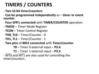
  • 1. TIMERS / COUNTERS - Two 16 bit timer/counters - Can be programmed independently as – timer or event counter. - Four-SFR’s connected with TIMER/COUNTER operation - TMOD – Timer Mode Register - TCON – Timer Control Register - TH0, TL0 – Timer/Counter - 0 - TH1, TL1 – Timer/Counter - 1 - Two pins of 8051 connected with Timer/counter. T0 – Timer 0 external input – P3.4 T1 – Timer 1 external input – P3.5 - INT0 and INT1 are also used for controlling the timer/counters.
  • 2. Timer Operation Timer Register (TH0, TL0 or TH1, TL1) incremented every m/c cycle. Thus working at increment frequency of 1/12 of oscillator frequency ( for 12 oscillator machine cycle ). Any preset value i.e. initial count can be loaded to TH0, TL0 or TH1, TL1. For Example – Clock frequency = 12 MHZ Clock period = 1/12 µ sec Machine cycle time = 1 µ sec Thus timer register will be incremented every microsecond. - If timer is initialized to 0000H Max. count = FFFFH max. time measured = 216 µ sec = 26 x 210 µ sec ≈ 26 millisecond ≈ 64 millisecond = 65.5 millisecond
  • 3. Counter Operation - Counts pulses occurring at T0 pin (Timer/Counter 0) and/or T1 pin (Timer/counter 1). - May correspond to event like • Passing of railway coach from a point – axle counter • Rotation of speedometer cable – speedometer of vehicle • No. of persons visiting exhibition. - T0, T1 scanned every m/c cycle • nth m/c cycle – T1 or T0 = High • (n+1)th m/c – T1 or T0 = Low • Timer 0 or timer 1 incremented in (n+1)th m/c cycle - Count frequency = min 2 m/c cycle per count - T0- P3.4, T1- P3.5
  • 4. 2 m/c cycle In 12 MHz 8051 – m/c cycle = 1 µ sec - 8051 can count at the rate of 2 µ sec per count or higher - Any event when takes less than 2 µ sec may go unnoticed - C/T bit of TMOD selects Timer or counter operation for Timer 0 or Timer 1. - Timer/Counter operations are controlled by - Gate bit of TMOD - TR0 bit of TCON When Gate = 0 then TR0, TR1 act as Timer run control bits.
  • 5. - Thus make Gate = 0 in TMOD By making TR0 (TCON. 4) or TR1 (TCON. 6) = 1 . through instruction, Timer/Counter 0 or Timer/Counter 1 may be started. - For starting and stopping the Timer/Counter from outside through hardware.  Make Gate = 1, TR0 = 1 through software. - By making INT0 or INT1 pin High will start Timer/Counter 0 or Timer/Counter 1  Make INT0 or INT1 Low to stop the Timer/Counter.  INT0 - P3.2  INT1 - P3.3
  • 6. As value in Timer register rolls from all ones (i.e. FFFFH) to all zero’s (i.e. 0000H) interrupt flag (TF0 or TF1) will be set. - TF0 (for Timer 0) and TF1 (for Timer 1) are bits of TCON SFR.  IF Timer 0 or Timer 1 interrupt is enabled then program control will branch to interrupt servicing routine.
  • 7. Timer Register Interrupt TF0 Program Timer ISR RETI Timer modes Mode 0 Mode 1 Mode 2 Mode 3 - 4 modes 13 bit counter 16 bit counter 8 bit counter + auto reload Split operation – Timer 0
  • 8. - Modes are set by M1 M0 bits of TMOD register. Mode 0 - 13 bit counter operation - TH0, TL0 (for Timer 0) or TH1, TL1 (for Timer 1) used as 13 bit counter. - All 8 bits of TH0 or TH1 - 5 lower bits of TL0 or TL1 are used, for counting. - When count rolls over from all 1’s to all 0’s, interrupt flag TF0 or TF1 is set.
  • 9. OSC ÷ 12 C/T = 0 TH0 TL0 (8 bits) (5 bits) C/T = 1 TF0 Control T0 pin TR0 Gate INT0 pin Figure Timer 0, mode 0 - 13-bit counter Interrupt
  • 10. In above figure when C/T = 0 - timer operation  count incremented every m/c cycle. provided TR0 (TCON. 4) or TR1 (TCON. 6) = 1 and Gate (TMOD. 3) or (TMOD. 7) = 0 Other way is- TR0 or TR1 =1 - Gate = 1 and INT0 or INT1 = 1 - Thus by sending Logic High signal on INT0 (or INT1) pins Timer 0 or Timer 1 can be started.
  • 11. - This can be used for finding pulse width in the following way. C/T = 0 – Timer operation TR0 or TR1 = 1 Gate = 1 Source of pulse connected to INT0 or INT1 pin - When pulse goes high timer starts counting at the rate 1/12 clock frequency - Which pulse goes low – Timer stops. INT0 or INT1 = Low - causes interrupt.
  • 12. Timer Starts Timer Stops + Interrupt Generated - ISR can read the timer value. - ISR can store the timer value and process it as required by the application.
  • 13. Mode 1 – 16 bit counter OSC ÷ 12 C/T = 0 TH0 TL0 (8 bits) (8 bits) C/T = 1 TF0 Control T0 pin TR0 Gate INT0 pin Figure Timer 0, mode 1 - 16-bit counter. Interrupt
  • 14. - Operation same as mode 0 except that all bits of TH0, TL0 or TH1, TL1 are used. When count rolls over from all 1’s to all 0’s – TF0 or TF1 interrupt flag is set. - Causes interrupt if enabled.
  • 15. Mode 2 – 8 bit operation with auto reload OSC ÷ 12 C/T = 0 TL0 (8 bits) C/T = 1 TF0 Control T0 pin TR0 TH0 (8 bits) Gate INT0 pin Figure Timer 0, mode 2 - autoreload. Interrupt
  • 16. - Only TL0 or TL1 are used i.e. 8 bit counting. - Initial preset value is loaded to TH0 or TH1 by software. - The value is loaded to TL0 or TL1 by hardware automatically before starts of counting. - When count rolls from all 1’s (i.e. FFH) to all 0’s (i.e. 00H) - TF0 or TF1 flag is set - Preset value in TH0 or TH1 is reloaded to TL0 or TL1 - Operation i.e. Counting starts automatically.
  • 17. Mode 3 – Split operation – Timer 0 OSC ÷ 12 (1/12) fosc (1/12) fosc C/T = 0 TL0 (8 bits) TH0 (8 bits) C/T = 1 TF0 TF1 Interrupt Control T0 pin TR0 Gate INT0 pin (1/12) fosc Control TR1 Figure Timer 0, mode 3-split to two 8-bit counters. Interrupt
  • 18. - When Timer 0 is put in mode 3 - Acts as two 8 bit counters i.e. TL0 and TH0 become two separate counter. TL0 – 8 bit operation in mode 0 or mode 1 (Timer or Counter) controlled by C/T, TR0, Gate, INT0 – Sets TF0 when count rolls to all 0’s from all 1’s. TH0 – Timer function only. – Controlled by TR1 i.e. starts when TR1 = 1. When count rolls to all 0’s from all 1’s – TF1 flag is set.
  • 19. Note – TR1 and TF1 are used in Timer 0 (TH0) even though they are bits for Timer 1. When Timer 1 is put in mode 3 – It just holds the preset count – same as TR0 = 0 i.e. opening the switch. [Modes 0, 1 and 2 are mostly used]
  • 20. Timer Mode Control Register - TMOD Timer 1 Timer 0 Bit no. 7 6 5 4 3 2 1 0 Symbol Gate C/T M1 M0 Gate C/T M1 M0 M1 and M0 specify the mode as follows: M1 M0 Mode Description in brief 0 0 0 13-bit counter 0 1 1 16-bit counter 1 0 2 8-bit counter with autoreload 1 1 3 Split Timer 0 into two 8-bit counters or to stop Timer 1
  • 21. If C/T = 1, the timers function as counters to count the negative transitions at T0 or T1 pins. If C/T = 0, the timers function as timers, that is, they basically count the number of machine cycles. Gate = 0 means that the timer is controlled by TR1 or TR0 only, irrespective of INT0 or INT1. Gate = 1 means that the timer control will depend on INT0 or INT1 and also on TR0 or TR1 bits
  • 22. When data is written it gets latched. TMOD is used for setting mode bits M1, M0, Gate bit and C/T for Timer 0 and Timer 1. Bit 0 to 3 for Timer 0. Bit 4 to 7 for Timer 1.
  • 23. Timer Control Register - TCON Bit 0 to 3 – used for interrupt functions Bit 4 to 7 – used for setting TR0, TR1 by software - Setting TF0, TF1 by counter i.e. hardware When count rolls from all 1’s to all 0’s.
  • 24. Bit no. 7 6 5 4 3 2 1 0 Symbol TF1 TR1 TF0 TR0 IE1 IT1 IE0 IT0 TF1: Timer 1 overflow flag. Set by hardware when the timer/counter overflows. Cleared by hardware when the processor vectors to the interrupt routine. TR1: Timer 1 run control bit. Set/cleared by software to turn the timer/counter on/off. TF0: Timer 0 overflow flag. Set by hardware when the timer/counter overflows. Cleared by hardware when the processor vectors to the interrupt routine. TR0: Timer 0 run control bit. Set/cleared by software to turn the timer/counter on/off.
  • 25. Example – a. Configuring Timer/Counter using TMOD Timer 1 7 Gate Timer 0 6 5 4 3 2 1 0 C/T M1 M0 Gate C/T M1 M0
  • 26. TIMER 1 - TIMER Mode = 00 (13 bit operation) TR1 C/T = 0 M1 M0 = 00 Gate = 0 TIMER 0 - Counter Mode = 01 (16 bit operation) TR0 C/T = 1 M1 M0 = 01 Gate = 0 TMOD = 0 0 0 0 0 1 0 1 = 0 5 H MOV TMOD, #05H
  • 27. b. To load initial count as preset value - Work out the preset value = ABCDH – Timer 0 - Load the preset value = 0000H - Timer 1 MOV MOV MOV MOV TL0, TH0, TL1, TH1, #CDH #ABH #00H #00H Timer 0 Timer 1
  • 28. c. Start Timer/Counter through TR0, TR1 7 TCON = TF1 6 5 4 3 2 1 0 TR1 TF0 TR0 IE1 IT1 IE0 IT0 Timer Interrupt Make TR0 = 1, TR1 = 1 TCON = 0 1 0 1 0 0 0 0 = 5 0 H MOV TCON, #50H or SETB TCON.4 SETB TCON.6
  • 29. d. When count value in Timer Register transits from all 1’s to all 0’s - Following tasks need to be done. Preset value to be loaded to Timer Register Timer interrupt flag (TF0 or TF1) to be cleared For continuous operation of Timer/Counter Time clock Pulse train generation etc.
  • 30. - Can be achieved in 2 ways: 1. - Check Timer interrupt flag in loop. JNB TCON.5, $ or JNB TCON.7, $ - When interrupt flag is set then clear the flag. CLR TCON.5 or CLR TCON.7 - Load the preset count and restart SJMP to b
  • 31. 2. Write ISR for Timer 0 or Timer 1 and store at location 000BH (for Timer 0) or 001BH (for Timer 1) - Enable Timer 0 or Timer 1 interrupt by making bits ET0 (IE.1) or ET1(IE.3) = 1. SETB IE.1 or SETB IE.3 - When TF0 or TF1 is set - Interrupt will occur and program will branch to ISR location (000BH for Timer 0) or (001BH for Timer 1).
  • 32. - ISR - clear flag TF0 or TF1 - load preset value - Restart timer/counter RETI Step d will be different for different applications. Example -1 - Generate a square wave of 50% duty cycle at pin p1.7. Use Timer 1 to generate time delay. Clock frequency = 12 MHz, 12 oscillator clock. Pulse width = 50 millisecond. - Let us work out the initial preset value.
  • 33. 50 ms 50 ms 1 m/c cycle = 1 microsecond 50 millisecond = 50 x 103 microsecond = 50, 000 m/c cycle FFFF = 65535 Difference = 65535 - 50000 = 15535 m/c cycle - Since count will roll from FFFF to 0000 additional m/c cycle will be required to set TF0 or TF1 .
  • 34. Thus initial count must be 15536 i.e. = 3CB0H By putting initial preset count of 3CB0H (or 15536 decimal), the register will reach FFFF in 49999 m/c cycle and roll over to 0000 in 50,000th m/c cycle accounting for 50 millisecond
  • 35. a. Configure Timer 1 7 0 6 0 5 0 4 1 3 0 2 0 1 0 Gate = 0, C/T = 0, Mode = 01 (16 bit operator) MOV TMOD , # 1 0 H Make P1.7 = Low initially CLR P1.7 b. Load Preset Value KK : MOV MOV TL1, #B0H TH1, #3CH 0 0 = 10H
  • 36. c. Complement P1.7 CPL P1.7 d. Start Timer 1 (TR1 = 1) SETB TCON.6 e. Check for TF1=1 in loop JNB TCON.7, $ f. TF1=1, Make TF1=0 CLR TCON.7 g. Stop Timer 1 Make TR1=0 CLR TCON.6 h. SJMP KK To reload preset value Complement P1.7 Start Timer 1.
  • 37. Steps d to g can be written as subroutine. Modified Program MOV CLR KK. MOV MOV CPL ACALL SJMP TMOD, #10H P1.7 TL1, #B0H TH1, #3CH P1.7 TDELY KK
  • 39. Example -2 - Generate a square wave of ON time of 3 ms and OFF time of 2 ms on P1.0. Clock frequency = 16 MHz, 12 clock m/c cycle - 16 MHz Frequency using Timer 1. 1 clock period = 1/16 µ sec
  • 40. - 1 m/c cycle = 12/16 µ sec = ¾ µ sec 1 ms = 1000 µ sec = 4000/3 m/c cycle ≈ 1333 m/c cycle - 2 ms ≈ 2666 m/c cycle. Accounting for additional m/c cycle – 2665 - 3 ms ≈ 4000 m/c cycle. Accounting for additional m/c cycle – 3999
  • 41. Count can be very well represented in 16 bits. Thus for 2 ms delay – 65535 – 2665 = 62870 =F596H for 3 ms delay – 65535 – 3999 = 61536 = F060H ; Configure Timer 1 MOV TMOD = TMOD, #10H 0 0 0 1 0 0 0 0 = 10H
  • 42. ; Load preset value for 3 ms KK : MOV TL1, #60H MOV TH1, #F0H ; Make P1.0 = High SETB P1.0 ; Start Timer 1 SETB TCON.6 ; Check for TF1 in loop JNB TCON.7, $ ; Make P1.0 = Low CLR P1.0
  • 43. ; TF1 = 1, Make TF1 = 0 CLR TCON.7 ; Stop Timer 1, Take TR1 = 0 CLR TCON.6 ; Repeat for 2 ms. . MOV TL1, #96H . MOV TH1, #F5H . SETB TCON.6 . JNB TCON.7, $ . SJMP KK.
  • 44. Example – 8051 with clock frequency = 18 MHz a. Generate a square wave of frequency 2 KHz on pin P1.0 using mode 2. b. Calculate the smallest frequency possible without using software counter.  Clock frequency = 18 MHz Clock period = 1/18 µ sec. 1 m/c cycle = 12/18 µ sec = 2/3 µ sec.
  • 45.  2 KHz square wave clock period = ½ 10-3 sec. = 0.5 millisecond <- - - - - - 0.5 ms - - - - -> Up time = 0.25 ms Dn time = 0.25 ms Up time = 0.25 ms = 0.25 x 10³ µ sec No. of m/c cycles in up time = (¼ x 103)/(2/3) = ¼ x 103 x 3/2 = 3/8 x 103 = 3000/8 = (30 x 25)/2 = 15 x 25 = 375
  • 46. - Delay of 375 m/c cycle can be achieved in many ways. 375/3 = 125 – Generate delay of 125 m/c cycle 3 times 375/5 = 75 – Generate delay of 75 m/c cycle 5 times 375/15 = 25 – Generate delay of 25 m/c cycle 15 times : : : We can take any of the options. Let us take 1st one.
  • 47. To generate delay of 125 m/c cycle Preset = (FFH) 255 – 125 = 130 Accounting for additional m/c cycle Preset = 131 = 83H ; Configure TMOD. Let us use Timer 0 TMOD = MOV 0 0 0 0 TMOD, #02H 0 0 1 0 = 02H
  • 48. ; Set P1.0 = High SETB P1.0 ; Load preset count MOV TH0, #83H ; Declare software counter ;Loop: MOV R3, 03H ; Start Timer
  • 49. KK: ; Check ; ; ; ; SETB TCON.4 TF0 in loop JNB TCON.5, $ Stop timer by making TR0=0 CLR TCON.4 Clear TF0 Flag CLR TCON.5 Decrement and Branch to start timer. DJNZ R3, KK. Delay of 375 m/c cycle completed. CPL P1.0 SJMP Loop.
  • 50. b. – Frequency is smallest when clock period = maximum i.e. Up time and Down time = maximum i.e. Delay is maximum. Delay is maximum when preset value =0 i.e. No. of m/c cycles in Up time = FF+1 No. of m/c cycles in Dn time = FF+1 Up time = 256 x 2/3 µ sec = 512/3 ≈ 170 µ sec Clock period = 341 µ sec. Frequency = 1/341 MHz = 1000/341 KHz = 2.92 KHz
  • 51. Example – Counter Operation - Design a counter to count pulses input at P3.4. - Determine the no. of pulses received in 1 minute. - 8051 is 12 MHz, 12 Clock m/c cycle. -> P3.4 pin is T0 i.e. -> external input to Timer 0 TMOD = 0 0 0 0 0 1 0 1 C/T = 1 – Counter operation Gate = 0, M1 M0 = 01 - 16 bit operation = 05H
  • 52. ; ; Initialize REPT: MOV TMOD, #05H Timer value to 0000H MOV TH0, #00H MOV TL0, #00H ; Start Counterby making TR0 = 1 SETB TCON.4 ACALL DELIM ; Read timer value and output on P2, P1 MOV A, TL0 MOV P1, A MOV A, TH0 MOV P2, A SJMP REPT
  • 54. Let us calculate the maximum no. of pulses that can be counted. - In 16 bit operation i.e. Mode 01 – (FFFF+1) = 65535 + 1 = 65536 - In 13 bit operation i.e. Mode 00 – 1FFF+1 = 8191 = 8192 - In 8 bit operation i.e. Mode 02 & Mode 03 – FF+1 = 255+1 = 256
  • 55. Let us assume that 1 pulse corresponds to – one rotation of is wheel – circumference of wheel = 1 meter Max. distance travelled in 1 minute can be measured as 8 bit operation – 256 meter. 13 bit operation – 8192 meter 16 bit operation – 65536 meter. Considering that overflow takes place in 1 minute duration
  • 56. Max. distance travelled in 1 hour that can be measured with be 8 bit operation – 256 x 60 = 14760 meter = 14.76 KMPH 13 bit operation – 8192 x 60 = 491520 = 491.52 KMPH 16 bit operation – 65536 x 60 = 3932160 meter. = 3932.16 KMPH
  • 57. For measuring automobile speed – 13 bit or 16 bit operation will be o.k. - Delay operation can also be managed using hardware timer so that micro controller is free for carrying out other tasks. Let us assume that Timer 1 is used for incorporating 1 minute delay 12 MHz clock 1 m/c cycle = 1 µ sec 1 second = 106 µ sec = 106 m/c cycle = 220 m/c cycle = 24 x 216 m/c cycle.
  • 58.  Thus 0000 to FFFF+1, counter has to repeat 16 times for delay of 1 sec.  For 1 Minute delay 1 minute = 60 x 16 x216 – 1 second delay must be repeated in loop by 60 times Now, TMOD will become 0 0 0 1 0 1 0 1 = 15 H C/T = 0 for Timer 1 – Timer operation MOV TMOD, #05H will get modified to MOV TMOD, #15H
  • 59. DELIM Subroutine DELIM: MOV LOOP1: MOV LOOP2: ; Start MOV MOV Timer 1 SETB JNB CLR CLR DJNZ DJNZ RET R3, #3CH ; for 60 seconds R4, #10H ; for 16 times repeat for 1 second TH1, #00H TL1, #00H TCON.6 TCON.7, $ TCON.6 TCON.7 R4, LOOP2 R3, LOOP1  We could also use interrupt servicing routine of timer interrupt for this purpose.