D132027
•
0 gostou•432 visualizações

International Refereed Journal of Engineering and Science (IRJES) is a peer reviewed online journal for professionals and researchers in the field of computer science. The main aim is to resolve emerging and outstanding problems revealed by recent social and technological change. IJRES provides the platform for the researchers to present and evaluate their work from both theoretical and technical aspects and to share their views. www.irjes.com

Recomendados
Mais conteúdo relacionado
Mais procurados
Mais procurados (20)
Destaque
Destaque (7)
Semelhante a D132027
Semelhante a D132027 (20)
Mais de irjes
Mais de irjes (20)
Último
Último (20)
D132027
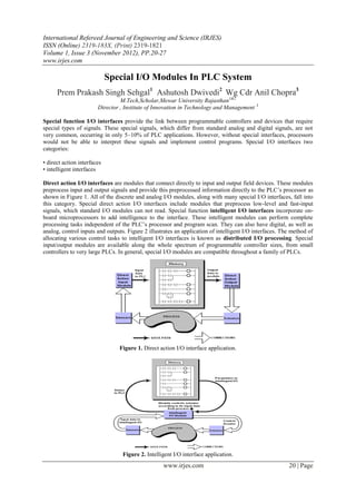
- 1. International Refereed Journal of Engineering and Science (IRJES) ISSN (Online) 2319-183X, (Print) 2319-1821 Volume 1, Issue 3 (November 2012), PP.20-27 www.irjes.com Special I/O Modules In PLC System Prem Prakash Singh Sehgal1 Ashutosh Dwivedi2 Wg Cdr Anil Chopra3 M.Tech,Scholar,Mewar University Rajasthan1&2 Director , Institute of Innovation in Technology and Management 3 Special function I/O interfaces provide the link between programmable controllers and devices that require special types of signals. These special signals, which differ from standard analog and digital signals, are not very common, occurring in only 5–10% of PLC applications. However, without special interfaces, processors would not be able to interpret these signals and implement control programs. Special I/O interfaces two categories: • direct action interfaces • intelligent interfaces Direct action I/O interfaces are modules that connect directly to input and output field devices. These modules preprocess input and output signals and provide this preprocessed information directly to the PLC’s processor as shown in Figure 1. All of the discrete and analog I/O modules, along with many special I/O interfaces, fall into this category. Special direct action I/O interfaces include modules that preprocess low-level and fast-input signals, which standard I/O modules can not read. Special function intelligent I/O interfaces incorporate on- board microprocessors to add intelligence to the interface. These intelligent modules can perform complete processing tasks independent of the PLC’s processor and program scan. They can also have digital, as well as analog, control inputs and outputs. Figure 2 illustrates an application of intelligent I/O interfaces. The method of allocating various control tasks to intelligent I/O interfaces is known as distributed I/O processing. Special input/output modules are available along the whole spectrum of programmable controller sizes, from small controllers to very large PLCs. In general, special I/O modules are compatible throughout a family of PLCs. Figure 1. Direct action I/O interface application. Figure 2. Intelligent I/O interface application. www.irjes.com 20 | Page
- 2. Special I/O Modules In Plc System Most commonly special I/O Interfaces in use are as follows: • Special discrete • Special analog • Positioning • Communication/computer/network • Fuzzy logic SPECIAL DISCRETE INTERFACES FAST - INPUT/PULSE STRETCHER MODULES Fast-input interfaces detect input pulses of very short duration. Certain devices generate signals that are much faster than the PLC scan time and thus cannot be detected through regular I/O modules. Fast-response input interfaces operate as pulse stretchers, enabling the input signal to remain valid for one scan. If a PLC has immediate input instruction capabilities, it can respond to these fast inputs, which initiate an interrupt routine in the control program. The input voltage range of a fast-input interface is normally between 10 and 24 VDC for a valid ON (1) signal, with the leading or trailing edge of the input triggering the signal (see Figure 3). When the interface is triggered, it stretches the input signal and makes it available to the processor. It also provides filtering and isolation; however, filtering causes a very short input delay, since the normal input devices connected to this type of interface do not have contact bounce. Typical fast-input devices, including proximity switches, photoelectric cells, and instrumentation equipment, provide pulse signals with durations of 50 to 100 microseconds. Connections to fast-input modules are the same as for standard DC input modules. Depending on the module, the field device must meet the sourcing or sinking requirements of the interface for proper operation. Usually, field devices must source a required amount of current to the fast-input module at the rated DC voltage. Figure 3. Pulse stretching in a fast-input module. WIRE INPUT FAULT MODULES Wire input fault modules are special input interfaces designed to detect short-circuit or open-circuit connections between the module and input devices. Wire input fault modules operate like standard DC input modules in that they detect a signal and pass it to the processor for storage in the input table. These modules, however, are specially designed to detect any malfunction associated with the connections. Figure 8-4 illustrates a simplified block diagram of Allen-Bradley’s wire input fault module. Typical applications of this module include critical input connections that must be monitored for correct wiring and field device operation. Figure 4. Wire input fault module diagram www.irjes.com 21 | Page
- 3. Special I/O Modules In Plc System Wire input fault interfaces detect a short-circuit or open-circuit wire by sensing a change in the current. When the input is OFF (0), the interface sends a 6 mA current through a shunt resistor (placed across the input device) for each input; when the input is ON (1), the interface sends a 20 mA current. An opened or shorted input will disrupt this monitoring current, causing the module to detect a wire fault. The module signals this fault by flashing the corresponding status LED. The control program can also detect the fault and initiate the appropriate preprogrammed action. Figure 5 illustrates a typical connection diagram for a wire input fault interface. Note that shunt resistors must be connected to the interface even though an input device is not wired to the module. The rating of the shunt resistor depends on the DC power supply voltage level used. This supply may range from 15 to 30 VDC. Although it is unlikely to occur, the total wire resistance of the connecting wire must not exceed the specified ohm rating for the DC supply voltage level. This wire resistance value is computed by multiplying the per foot ohm value by the total length of the wire connection. For example, a size 14 wire that has a resistance of 0.002525 ohms per foot should have a total wire resistance of less than 25 ohms when connected to a 15 VDC power supply. This implies that the wire should not exceed 9,900 feet in length (25 0 .002525 = 9,900). Figure 5. Wire input fault module connection diagram. FAST-RESPONSE INTERFACES Fast-response interfaces are extensions of fast-input modules. These interfaces detect fast inputs and respond with an output. The speed at which this occurs can be as short as 1 m sec from the sensing of the input to the output response. The output response time is independent of the PLC processor and the scan time. Fast-response modules have advantages that include the ability to respond to very fast input events, which require an almost immediate output response. For example, the detection of a feeder jam in a high-speed assembling or transporting line may require the module to send a fast disengage signal to the product feed, thus reducing the amount of product jammed or lost. During operation, a fast-response module receives an enable signal from the processor (through the control program), which readies it for ―catching‖ the fast input. Once the active module receives the signal, it sends an output and remains ON until the processor (via the ladder program) disables it, thereby resetting the output. Figure 6 illustrates a block diagram of this interface’s operation, along with its logic and timing. Figure 7 illustrates how a fast response interface functions. Furthermore, Figure 8 shows Allen-Bradley’s version of a fast-response www.irjes.com 22 | Page
- 4. Special I/O Modules In Plc System Figure 6. (a) Block diagram, (b) logic representation, and (c) timing diagram of a fast-response interface. module, called a High-Speed Logic Controller Module (1771-DR), which offers 8 inputs and 4 outputs that switch ON less than 1 m sec after the detection of the fast input. Figure 7. Fast-response interface. Figure 8. Allen-Bradley’s fast-response module (1771-DR). SPECIAL ANALOG, TEMPERATURE, AND PID INTERFACES Weight input modules are special types of analog interfaces designed to read data from load cells, which are standard on storage tanks, reactor vessels, and other devices used in blending and batching operations. www.irjes.com 23 | Page
- 5. Special I/O Modules In Plc System Figure 9 illustrates the configuration of a weight input application, while Figure 10 shows Allen-Bradley’s weight input interface called the Weigh Scale Module (1771-WS). These weight modules support the industry standard of 2 or 3 milli volts per volt (mV/V) load cells. Figure 9. Weight input application configuration Figure 10. Allen-Bradley’s Weigh Scale Module (1771-WS). A weight input module provides the excitation voltage for load cells, as well as the necessary software for calibrating load cell circuits. A weight module sends an excitation voltage to a load cell and reads the signal created by the weight force exerted on the cell. The module’s A/D converter then processes this information and passes it to the processor as a weight value. This eliminates the need for the PLC to convert the load cell’s analog signal. Additionally, a weight module incorporates a calibration feature that avoids problems with calibration of the load cell system. POSITIONING INTERFACES Positioning interfaces are intelligent modules that provide position-related feedback and control output information in machine axis control applications. The motion control capabilities of positioning modules allow some programmable controllers to perform functions, using servo mechanisms (e.g., point-to-point control and axis positioning), that once required computer numerical control (CNC) machines. Positioning interfaces use PLC instructions that transfer blocks of data at a time (see Figure 11). This data includes initialization parameters, distances and limits, and velocities. Instructions, such as block transfer in/out and move data in/out, are typically used to implement this transfer of information. www.irjes.com 24 | Page
- 6. Special I/O Modules In Plc System Figure 11. Positioning interface configuration. BASIC modules, also referred to as data-processing modules, are intelligent I/O interfaces capable of performing computational tasks without burdening the PLC processor’s computing time. In contrast to other intelligent I/O interfaces, such as servo controls, a BASIC module does not actually command or control specific field devices. Rather, it complements the performance of the PLC system. Network interface modules allow a number of PLCs and other intelligent devices to communicate and pass PLC data over a high speed local area communication network. Any device may interface with the network, because the network is not restricted to only products designed by the network’s manufacturer. A network interface module implements all of the necessary communication connections and protocols to ensure that a message is accurately passed along the network. In general, when a processor or other network device sends a message, its network interface transmits the message over the network at the network’s baud rate speed. The receiving network interface accepts the transmission, passes the information to the CPU, and if necessary, sends a command to the intended field device. As you will see in Chapter 18, the speed and protocol for the communication link varies depending on the network. Depending on the network type and configuration, a network module can be connected, at a distance of up to 10,000 feet, with 100 to 1000 devices (nodes). The communication media—twinaxial, coaxial, or twisted-pair—varies depending on the type of network. The different types of networks also utilize specific network interfaces. For example, a device-level CANbus network uses a CANbus-type interface. Figure 12 illustrates a typical configuration of a PLC network using the different types of network interface modules. Figure 12. (a) A standard PLC local area network www.irjes.com 25 | Page
- 7. Special I/O Modules In Plc System Figure 12.(b) A PLC local area network with CANbus (device bus) and Field bus (process bus) sub-networks. FUZZY LOGIC INTERFACES Fuzzy logic interfaces, which are offered by a few PLC manufacturers, provide a way of implementing fuzzy logic algorithms in PLCs. Fuzzy logic algorithms analyze input data to provide control of a process. As shown in Figure 13, Figure 13 Fuzzy logic interface application fuzzy logic modules do not function as actual input and output interfaces per se. Rather, they work with other input and output interfaces, providing an intelligent link between the two. Fuzzy logic modules are an integral part of the advanced capabilities of today’s programmable controllers. They help to bridge the gap between the discrete and analog decision-making functions of a PLC. In essence, fuzzy logic modules allow PLCs to ―reason,‖ letting them interpret data in an analog-type form instead of just as ON or OFF. For example, a typical PLC connected to a temperature-sensing device can only sense whether a temperature is acceptable or unacceptable (see Figure 14 a). That is, the temperatures between 60F and 80F are acceptable (logic 1); all other temperaturesare unacceptable (logic 0). A PLC with fuzzy logic capabilities, however, can discern between the ranges of acceptable and unacceptable temperatures, judging a temperature to be either more acceptable or less acceptable (see Figure 14 www.irjes.com 26 | Page
- 8. Special I/O Modules In Plc System b). Thus, a fuzzy logic module can determine that 62F is an acceptable temperature, but that it is not as acceptable as 70F. Figure 14. Temperature sensing in (a) a normal PLC and (b) a PLC with fuzzy logic capabilities. The ―reasoning‖ capabilities of fuzzy modules allow them to provide fine-tuned control of analog processes, as well as nonlinear and time-variant processes, like tension and position control. These types of hard-to-control systems usually provide gross input deviations or insufficient input resolution, which often require human intuition and judgment. Fuzzy logic modules can provide this type of human-like judgment. References: [1.] D. E. Seborg, T.F. Edgar, D.A. Malichamp, Process Dynamics and control, Wiley, 1988 [2.] G. Warnock, Programmable Controllers: Operation and application, Prentice Hall, 1988 [3.] R. w. Lewis, Programming Industrial Control Systems Using IEC 1131-1, IEE Press, 1998 www.irjes.com 27 | Page