SlideShare uma empresa Scribd logo
1 de 14
International Journal of Computational Engineering Research||Vol, 03||Issue, 6||
www.ijceronline.com ||June||2013|| Page 39
Analytical Review of Model Simplification Aspects for Wind
Turbine Based Doubly Fed Induction Generator.
Amit Nehete1
, Amit Pathak2 ,
Bhakti Chaughule3
1,2,3,
M.Tech Pursuer (Power System), Bharati Vidyapeeth University’s College of Engg, Pune.
I. INTRODUCTION
Share of wind energy in the power system has been increasing with the time. The use of variable speed
wind energy conversion systems is becoming more popular due to the development in the field of power
electronics. Currently, the doubly fed induction generator (DFIG) wind turbines dominate the market due to
cost-effective provision of variable-speed operation with constant frequency. DFIG is a wound rotor induction
generator in which rotor winding is fed through back to back variable frequency variable voltage source
convertors. Their ability to control electrical torque and reactive power offer superior performance concerning
system stability. With changing wind speed, one can adjust the frequency of the injected rotor voltage of the
DFIG to obtain a constant-frequency at the stator. Adequate modeling of these systems and clear
understanding of the effects of different simplifications is paramount if reliable results of simulations of power
systems with high penetration of DFIG-based wind plants are sought. Efficient modeling and simulation
techniques for induction generators will facilitate the research on wind turbine generation. . The wind energy
industry is rather opaque regarding modeling as most of the data is usually confidential or requires rigorous field
or laboratory experiments. The DFIG mathematical models are simplified either in order to save computational
time or to eliminate the requirement for hard-to obtain data. In order to investigate the impacts of DFIGs
installations on the operation and control of the power system, accurate models are required. A fifth order and
reduced order (3rd) machine models are discussed. To derive more accuracy in these modeling orders more
simplified and accurate models are also included in the review. The response of the DFIG for voltage control
(VC) and its performance during a network fault especially voltage sags are addressed. Here presented is the
analysis of the previously published papers, this paper aims to clarify some of the uncertainties associated with
DFIG modeling. It also provides numerous simulation results that illustrate the influence of different parameters
and modeling on transient operation of DFIG-based wind plants.
In this paper, Section II takes the overview of the assumptions to be made along with the choice of
reference frame for particular modeling. Section III focuses on equations of various modeling and their
simplifications. Section IV includes the results of simulations performed to validate the previous. Section V
analyses those results from utility point of view and section VI concludes.
ABSTRACT
There has been a fast growing demand for the application of doubly fed induction generators
(DFIG) in wind power plants in recent years. They have in particular dominated the market in last two
years. DFIG is an ideal candidate to satisfy the requirements of the recently proposed challenging
grid codes. In order to investigate the transient response of doubly fed induction generator (DFIG)
under various disturbances, an accurate modeling is required. In this paper simulation results of
transient responses of DFIG during faults for different order models are reviewed. However, many
uncertainties still exist regarding validated comprehensive DFIG models. This paper attempts to
clarify the ambiguities in various model orders. Impact of various orders such as fifth, third and
simplified model, accurate model including saturation, excluding saturation is discussed here. A brief
review of assumptions and considerations with the choice of reference frames is also included.
KEY WORDS: DFIG, Electric variables control, Flux Saturation, Induction Machine, Machine
Models, Power system transient stability, Wind energy generation
Analytical Review Of Model Simplification…
www.ijceronline.com ||June||2013|| Page 40
1.1.Overview of Considerations
Three phase stator and rotor windings of an induction machine can be represented by two sets of orthogonal
fictious coils. d-q or two axis model for the study of transient behavior has proven to be reliable and accurate.
Though rotation of the d-q axis can be arbitrary, three reference speeds i.e reference frames as follows,
- The stationary reference frame - the d,q axes do not rotate;
- The synchronously rotating reference frame - the d,q axes rotate at synchronous speed;
- The rotor reference frame - the d,q axes rotate at rotor speed.
Following explains choice of reference frame as elaborated in [9]
A. Stationary reference frame
When θ = 0; the d, q axes do not rotate therefore it called as stationary reference frame. Also the +d-
axis is chosen to coincide with the stator phase A axis.
If the bus-bar voltages are
… (1)
If the motor terminals are directly connected to bus-bar and by using parks transformation
… (2)
From the above equations; the voltage applied to the stator d-axis coil, is the same as the stator phase A
voltage. i.e where Vas is a stator phase A voltage and Vds is stator d-axis coil voltage. This means
that the stator d-axis current Ids exactly equal to the phase A current Ias therefore it is not necessary to compute
Ias separately at each step of integration process through inverse parks transformation This saves computer time
and hence is an advantage of the stationary reference frame.
B. Synchronously rotating reference frame
When θ = the d, q axes rotate at synchronous speed. Therefore it is called synchronously rotating
frame, without any capacitor the terminal voltage changes from eqn ( 2) to
…(3)
This means that the stator voltages are DC quantities and this has advantages in the field of feedback controller
design when the motor equations are linearized around a steady operating point. In this frame we can use larger
step length while digital integration; since the variables are slowly changing DC quantities during transient
conditions.
C. Rotor reference frame
When θ = ; The d, q reference frame rotate at rotor speed therefore it is called rotor reference
frame, also the d-axis position coincides with the rotor phase A axis.
Without any capacitors the terminal voltages changes from eqn (2)
… (4)
The d, q voltages are therefore of slip frequency and the d-axis rotor current behaves exactly as the
phase A rotor current does. This means that it is not necessary to compute the phase A rotor current at each
step of the digital integration process through the inverse of Park's transform. This saves computer time and
hence is an advantage of the rotor reference frame when studying rotor quantities.The model of an induction
generator can have various orders. 5th
order model is considered to be a full order model for an induction
generator. When fifth i.e full order model is to be used, it demands consideration of differential equations for the
whole network as stator circuit is directly connected to the stator circuit. Simplified fifth order doesn’t take into
Analytical Review Of Model Simplification…
www.ijceronline.com ||June||2013|| Page 41
account certain terms with low weight and employs the FOC algorithm. Third order model excludes stator
dynamics reducing the step size for computations. Differential equations of previous order are ignored while
developing this stage.In these orders effect of flux saturation is usually given no importance but its inclusion
leads to an accurate model.Per unit representation are desirable to be used while analysis as it enables the
conversion of whole system to pu quantities on a single power base.
II. VARIOUS MODELS OF DFIG
A. Fifth order model
The references [1][2][3][9] shows the fifth order model of the induction machine in Synchronous
reference frame. However in this model effect of main flux and leakage flux is neglected.
The equations (5) and (6) gives d and q axis voltages of stator and rotor windings respectively,
… (5)
… (6)
Equation (7) represents stator and rotor flux in d-q synchronous reference frame respectively,
… (7)
As in [3]voltage behind a transient model for DFIG can be obtained, by defining ed andeq,
… (8)
And with some manipulations,
… (9)
Analytical Review Of Model Simplification…
www.ijceronline.com ||June||2013|| Page 42
… (10)
The electromagnetic torque,
… (11)
And finally mechanical torque,
… (12)
These constitute fifth order model which includes stator transients and state variables are stator and rotor flux
components and the rotor speed as well. Current components based state space model can possibly be derived
by putting stator and rotor flux equations in voltage equations of the same. [1][2][3][5]
B. Third order model-
Neglecting the rate of change of stator flux linkage is a standard method of reducing the order of the
induction generator model. The reduced i.e third order model can be derived by ignoring the differential term in
equation (5). Neglecting the stator transients,
The reduced order d and q axis stator and rotor voltages,
… (13)
… (14)
When stator transients are neglected (9) can be reduced to,
… (15)
… (16)
The electromagnetic torque,
Analytical Review Of Model Simplification…
www.ijceronline.com ||June||2013|| Page 43
… (17)
In the third order model state variables are two components of the rotor flux linkage and rotor speed.
C. Simplified modeling of DFIG-
To study behavior of DFIG-based WTs under generic conditions the fifth-order model is popular. But
this kind of model raises a complicated system. A complex analysis under transient conditions, the high
computational cost of the equation in standards simulators necessitates development of aggregated models.
Considering
1) A field-oriented control (FOC) algorithm for the rotor side converter acts as a current source.
2) Synchronous reference frame.Certain low weight components of the equations in the system and the stator
electric transient are neglected.Simplified fifth order model enables simplification of some terms of the stator
voltage. FOC algorithm regulates dq components of the rotor currents to be injected to the DFIG to perform a
decoupled control of the positive sequence of P and Q.Considering the voltage and flux equations of stator and
rotor in fifth order model (eq. 5, 6, 7) linear and applying the Laplace transform, the stator currents in the
synchronous reference frame are obtained. Some necessary manipulations with abovementioned considerations
give the simplified model as in [3],
… (18)
It can be easily observed that the stator voltage and rotor current appear as input variables. Any variation in the
stator voltage will introduce oscillations in the dq components of the stator currents in the synchronous
reference frame.
Accuracy of the simplified model with respect to the resolution of a fifth order are observed by plotting
responses of both systems on same graph as in [3].
D. Accurate model-
By reducing the order of the generator computational time can be considerably reduced. Reduced order
can be achieved by neglecting differential term in the voltage equations of the machine. [1-4][9] The effect of
leakage flux saturation is usually neglected in these papers. In some papers saturation effect is considered but
lacks the comparative study among different orders of DFIG model with saturation effect during three phase
sag, this is proposed in [4] developing an accurate model. Better representation of the induction machine with
saturation under transient condition demands the consideration of variation in the stator and rotor leakage
inductances due to saturation in the leakage flux path in saturation effect. To account effect of saturation in
leakage flux path, unsaturated stator and rotor leakage reactances in dynamic models in [1-4] are modified by
saturation factor K sat.
Ksat is introduced as follows,
… (19)
Where is equal to the ratio between current at which the saturation begins, Isat, to the current through the
leakage reactance. [4][6]
In [4] a 50% voltage sag is considered for simulation. At t = 5s, a voltage sag happens. Then at t =7s the voltage
is restored to its presage value, i.e. 1 pu.
Analytical Review Of Model Simplification…
www.ijceronline.com ||June||2013|| Page 44
III. RESULTS
Simulations carried out to investigate the performance of the DFIG during a system fault in [2]. A fault
is applied t=/49.85 s and cleared after 150 ms.
a)
b)
c)
d)
e)
f)
Analytical Review Of Model Simplification…
www.ijceronline.com ||June||2013|| Page 45
g)
h)
Fig. 1. Response of DFIG to the system fault (all are in pu)
Similar set of results as in fig. 1(a)-(f) for fifth order and third order modeling respectively are obtained for
terminal voltage, rotor speed, stator current and electromagnetic torque.
Another investigation of the Influence of various models can be seen in [9] as follows, the third and fifth order,
modeled in rotor reference frame.
Fig. 2(a) DFIG response to a 350 ms short circuit applied at 0s and removed crowbar at 0.5s.
Analytical Review Of Model Simplification…
www.ijceronline.com ||June||2013|| Page 46
Fig. 2(b) The rotor current response when simulated for 20 % voltage sag with no crowbar operation
Behavior of DFIG model under three phase to ground fault, one phase to ground fault, two phase to ground fault
with simplified and fifth order model as derived in [2] are as follows,
(a) Grid voltage waveforms
(b) Active and reactive power (in kVA).
(c) isq performance
Analytical Review Of Model Simplification…
www.ijceronline.com ||June||2013|| Page 47
(d) isd performance
Fig. 3.1 Behavior of the DFIG models under three-phase-to-ground faults with the simplified and fifth-order
models.
(a) Grid voltage waveforms.
(b) Active and reactive power (in kVA).
(c) isq performance
(d) isd performance
Fig.3.2 Behavior of the DFIG models under one-phase-to-ground faults with the simplified and fifth-order
models.
Analytical Review Of Model Simplification…
www.ijceronline.com ||June||2013|| Page 48
(a) Grid voltage waveforms.
(b) Active and reactive power (in kVA).
(c) isq performance
(d) isd performance
Fig. 3.3 Behavior of the DFIG models under two-phase-to-ground faults with the simplified and fifth-order
models.
Following figure shows the simulation results obtained in [4] for Torque, ids, iqs, speed for fifth, third and first
order model including and excluding saturation effect.
Analytical Review Of Model Simplification…
www.ijceronline.com ||June||2013|| Page 49
a)
b)
c)
d)
Analytical Review Of Model Simplification…
www.ijceronline.com ||June||2013|| Page 50
e)
f)
g)
h)
Fig. 4 DFIG transient response due to 50% voltage sag. (a) Torque at voltage sag occurrence, (b) torque at
voltage recovery, (c) ids at voltage sag occurrence, (d) ids at voltage recovery, (e) iqs at voltage sag occurrence,
(f) iqs at voltage recovery, (g) speed at voltage sag occurrence, and (h) speed at voltage recovery
Analytical Review Of Model Simplification…
www.ijceronline.com ||June||2013|| Page 51
IV. DISCUSSION
From the simulations in [2], the rotor current in pu appeared to be very similar to the stator current
during the transient. When Machine is operated with increased short term rating of RSC components, the used
control strategy and convertor ratings are the factors decide the rotor voltage applied to the DFIG during the
network fault. From the fig.1 it can be seen that DFIG response during the fault is more elaborative in the 5th
order generator model and includes the transient behavior of the stator current. The 3rd order model though
gives a similar mean value of the stator current; details of the transient remain unobserved.In these results Stator
flux transients in current, active and reactive power can be clearly traced in fifth order model which is not
observed in third order, third order model appears not useful to account for operations of crowbar protection. If
DFIG supports reactive power rotor phase A current is higher with fifth order model as seen in 2(a) instead
overall peak rotor current is lower as seen in Fig. 2(b). Electrical torque and magnetization of the machine is
controlled by q axis and d axis respectively with stator flux oriented reference frame. Fast stator flux change is
allowed in third order due to ignored stator flux transients. [3][5] Compared to third order model, Transients in q
axis current is higher & d axis current change is small with fifth order model attributes to higher rotor current in
third order model. Abrupt stator flux change leads induction of higher rotor current in case of third order and a
bit lower rotor current as stator flux change is slower.
For three phase fault, sudden reduction in voltage raises lower power injection in network which also
has dependency on RSC control during fault. Perfect matching of dynamic performance of simplified model
with fifth order model can be clearly observed in the behavior of ids and iqs. Oscillations seen in ids and iqs due to
low damping (conditioned by Rs of second order transfer function of eq.18 which is very low in DFIG) in the
system. When stator winding is affected by one phase to ground and two phases to ground fault, causes negative
sequence voltage translated in 120 Hz oscillations at stator which can be observed higher in second case.
Noticeable points in the results are Oscillating Vds which is ignored as its multiplied by lower terms compared to
Vqs evidenced the low influence and results of the fifth order are accurately tracked by results of simplified
model, precisely describe the dynamic behavior of the DFIG.Fig 4. Shows the simulation results obtained in [4].
At the occurrence of the fault current and torque increases with saturation. Oscillations aren’t observed in third
and first order model but noticeably in fifth order model. Difference between Saturation and unsaturated model
becomes visible as the order increases, hardly noticed in first order. There isn’t fall in rotor speed for third and
first order models but decreases for saturated and unsaturated model of fifth order.After recovery of fault fifth
order model appeared faster to reach steady state than third and first order model. Only transient response of
speed, torque and current is affected by saturation and not the steady state.
Table 1. Simplifications used in different order model
Table 1 shows simplifications employed in various modeling orders at a glance [4]
V. CONCLUSION
If the FOM is used for time-domain simulation, small integration step sizes are required as a result of
the small time constants involved. The small integration time step, in addition to the large number of differential
equations especially for the grid, results in considerable simulation efforts when studying large systems. These
disadvantages limit the applicability of the FOM to small grids. For classical, phasor domain electro-mechanical
dynamic studies of large power systems the simplicity and reduced computation time of the 3rd order model
appears attractive. For more detailed representations of fault current contribution and investigation of the
required ratings of the converters then the 5th order representation may be preferred.Two simple second order
transfer functions permit to carry out simulation of large scale wind energy applications. This lead to
considerable reduction in computational time as compared to fifth order in simulating behavior of Multiple
DFIG. Though complex model can also do, this model appears to be the intuitive estimator for designing
strategies of sag response improvement of DFIG.The stator and rotor current of DFIG calculated considering
saturation effect are much higher than the values calculated by ignoring it. Rotor speed of saturated model
attains steady state value faster as compared to unsaturated models; saturated fifth order reaches faster than
others.So saturation effect can be incorporated more importantly to study the transient performance of DFIG and
doesn’t prove that much useful for steady state.
Analytical Review Of Model Simplification…
www.ijceronline.com ||June||2013|| Page 52
REFERENCES
[1] Istvan Erlich, Jorg Kretschmann, Jens Fortman, Stephen Mueller-EngelHardt, and Holger Wrede, Modeling of wind turbines
based on Doubly-Fed Induction Generator for power system stability studies, IEEE Transactions on Power Systems, VOL 22,
No. 3, August 2007.
[2] J.B. Ekanayake, L. Holdsworth, N. Jenkins, Comparison of 5th order and 3rd order machine models for doubly fed induction
generator (DFIG) wind turbines, Electric Power Systems Research 67 (2003) 207_/215
[3] Alvaro Luna, Francisco Kleber de Araujo Lima, David Santos, Pedro Rodríguez, Edson H. Watanabe, Santiago Arnaltes,
Simplified Modeling of a DFIG for Transient Studies in Wind Power Applications, IEEE Transactions on Industrial Electronics,
VOL. 58, NO. 1, JANUARY 2011
[4] Alireza abbaszadeh, Saeed lesan, Vahid mortezapour, Transient response of doubly fed induction generator under voltage sag
using an accurate model.
[5] Pablo Ledesma, Julio Usaola, Effect of Neglecting Stator Transients in Doubly Fed Induction Generators Models, IEEE
Transactions on Energy Conversions, VOL. 19, NO. 2, JUNE 2004
[6] Hany M. Jabr, Narayan C. Kar, Effects of main and leakage flux saturation on the transient performances of doubly-fed wind
driven induction generator, Electric Power Systems Research 77 (2007) 1019–1027
[7] Andre´s Feijo´o, Jose´ Cidra´s, Camilo Carrillo, A third order model for the doubly-fed induction machine, Electric Power
Systems Research 56 (2000) 121–127
[8] R. J. Lee, P. Pillay and R. G. Harley, D,Q Reference Frames for the Simulation of Induction Motors, Electric Power Systems
Research, 8 (1984/85) 15 -26
[9] Mustafa Kayikçi and J. V. Milanovic´, Assessing Transient Response of DFIG-Based Wind Plants—The Influence of Model
Simplifications and Parameters, IEEE Transactions on Power Systems, VOL. 23, NO. 2, MAY 2008
[10] Zhixin Miao, Lingling Fan, The art of modeling and simulation of induction generator in wind generation applications using
high-order model, Simulation Modelling Practice and Theory 16 (2008) 1239–1253
Amit Nehete, M.Tech Electrical-Power System (Pursuing), Department of Electrical
Engineering, Bharati Vidhyapeeth University’s College of Engineering, Pune, India.
Amit Pathak, M.Tech Electrical-Power System (Pursuing), Department of Electrical
Engineering, Bharati Vidhyapeeth University’s College of Engineering, Pune, India.
Bhakti Chaughule, M.Tech Electrical-Power System (Pursuing), Department of Electrical
Engineering, Bharati Vidhyapeeth University’s College of Engineering, Pune, India.

Mais conteúdo relacionado

Mais procurados

2014 dtc of b4 inverter fed bldc motor
2014 dtc of b4 inverter fed bldc motor2014 dtc of b4 inverter fed bldc motor
2014 dtc of b4 inverter fed bldc motorvmuniyasamy
 
L021201085091
L021201085091L021201085091
L021201085091theijes
 
POWER SYSTEM SIMULATION LAB-1 MANUAL (ELECTRICAL - POWER SYSTEM ENGINEERING )
POWER SYSTEM SIMULATION LAB-1 MANUAL (ELECTRICAL - POWER SYSTEM ENGINEERING )POWER SYSTEM SIMULATION LAB-1 MANUAL (ELECTRICAL - POWER SYSTEM ENGINEERING )
POWER SYSTEM SIMULATION LAB-1 MANUAL (ELECTRICAL - POWER SYSTEM ENGINEERING )Mathankumar S
 
Convergence analysis of the triangular-based power flow method for AC distribu...
Convergence analysis of the triangular-based power flow method for AC distribu...Convergence analysis of the triangular-based power flow method for AC distribu...
Convergence analysis of the triangular-based power flow method for AC distribu...IJECEIAES
 
A Comparison Analysis of Unipolar and Bipolar Switching modulated Cascade H-B...
A Comparison Analysis of Unipolar and Bipolar Switching modulated Cascade H-B...A Comparison Analysis of Unipolar and Bipolar Switching modulated Cascade H-B...
A Comparison Analysis of Unipolar and Bipolar Switching modulated Cascade H-B...IJERA Editor
 
Elk 26-6-32-1711-330
Elk 26-6-32-1711-330Elk 26-6-32-1711-330
Elk 26-6-32-1711-330Mellah Hacene
 
Adoption of Park’s Transformation for Inverter Fed Drive
Adoption of Park’s Transformation for Inverter Fed DriveAdoption of Park’s Transformation for Inverter Fed Drive
Adoption of Park’s Transformation for Inverter Fed DriveIJPEDS-IAES
 
Speed Control System for BLDC Motor by using Direct Back EMF Detection Mathod
Speed Control System for BLDC Motor by using Direct Back EMF Detection MathodSpeed Control System for BLDC Motor by using Direct Back EMF Detection Mathod
Speed Control System for BLDC Motor by using Direct Back EMF Detection Mathodijtsrd
 
Simulation Approach to Speed Control of PMBLDC Motor using Various Control Te...
Simulation Approach to Speed Control of PMBLDC Motor using Various Control Te...Simulation Approach to Speed Control of PMBLDC Motor using Various Control Te...
Simulation Approach to Speed Control of PMBLDC Motor using Various Control Te...IJMTST Journal
 
4.[14 24]modeling, analysis and control of hexagram inverter for three- phase...
4.[14 24]modeling, analysis and control of hexagram inverter for three- phase...4.[14 24]modeling, analysis and control of hexagram inverter for three- phase...
4.[14 24]modeling, analysis and control of hexagram inverter for three- phase...Alexander Decker
 
11.modeling, analysis and control of hexagram inverter for three phase induc...
11.modeling, analysis and control of hexagram inverter for three  phase induc...11.modeling, analysis and control of hexagram inverter for three  phase induc...
11.modeling, analysis and control of hexagram inverter for three phase induc...Alexander Decker
 
A Novel Distribution System Power Flow Algorithm using Forward Backward Matri...
A Novel Distribution System Power Flow Algorithm using Forward Backward Matri...A Novel Distribution System Power Flow Algorithm using Forward Backward Matri...
A Novel Distribution System Power Flow Algorithm using Forward Backward Matri...iosrjce
 
A Review on Performance Analysis of Matrix Converter Fed AC Motor Drive
A Review on Performance Analysis of Matrix Converter Fed AC Motor DriveA Review on Performance Analysis of Matrix Converter Fed AC Motor Drive
A Review on Performance Analysis of Matrix Converter Fed AC Motor DriveIAES-IJPEDS
 
Performance & Analysis of Single-Phase Inverter Fed Three-phase Induction Mot...
Performance & Analysis of Single-Phase Inverter Fed Three-phase Induction Mot...Performance & Analysis of Single-Phase Inverter Fed Three-phase Induction Mot...
Performance & Analysis of Single-Phase Inverter Fed Three-phase Induction Mot...ijiert bestjournal
 
Optimal Placement of DG for Loss Reduction and Voltage Sag Mitigation in Radi...
Optimal Placement of DG for Loss Reduction and Voltage Sag Mitigation in Radi...Optimal Placement of DG for Loss Reduction and Voltage Sag Mitigation in Radi...
Optimal Placement of DG for Loss Reduction and Voltage Sag Mitigation in Radi...IDES Editor
 
Cascade forward neural network based on resilient backpropagation for simulta...
Cascade forward neural network based on resilient backpropagation for simulta...Cascade forward neural network based on resilient backpropagation for simulta...
Cascade forward neural network based on resilient backpropagation for simulta...Mellah Hacene
 

Mais procurados (20)

2014 dtc of b4 inverter fed bldc motor
2014 dtc of b4 inverter fed bldc motor2014 dtc of b4 inverter fed bldc motor
2014 dtc of b4 inverter fed bldc motor
 
L021201085091
L021201085091L021201085091
L021201085091
 
Modeling and simulation of quasi-Z-source indirect matrix converter for perma...
Modeling and simulation of quasi-Z-source indirect matrix converter for perma...Modeling and simulation of quasi-Z-source indirect matrix converter for perma...
Modeling and simulation of quasi-Z-source indirect matrix converter for perma...
 
POWER SYSTEM SIMULATION LAB-1 MANUAL (ELECTRICAL - POWER SYSTEM ENGINEERING )
POWER SYSTEM SIMULATION LAB-1 MANUAL (ELECTRICAL - POWER SYSTEM ENGINEERING )POWER SYSTEM SIMULATION LAB-1 MANUAL (ELECTRICAL - POWER SYSTEM ENGINEERING )
POWER SYSTEM SIMULATION LAB-1 MANUAL (ELECTRICAL - POWER SYSTEM ENGINEERING )
 
Convergence analysis of the triangular-based power flow method for AC distribu...
Convergence analysis of the triangular-based power flow method for AC distribu...Convergence analysis of the triangular-based power flow method for AC distribu...
Convergence analysis of the triangular-based power flow method for AC distribu...
 
A Comparison Analysis of Unipolar and Bipolar Switching modulated Cascade H-B...
A Comparison Analysis of Unipolar and Bipolar Switching modulated Cascade H-B...A Comparison Analysis of Unipolar and Bipolar Switching modulated Cascade H-B...
A Comparison Analysis of Unipolar and Bipolar Switching modulated Cascade H-B...
 
Elk 26-6-32-1711-330
Elk 26-6-32-1711-330Elk 26-6-32-1711-330
Elk 26-6-32-1711-330
 
Adoption of Park’s Transformation for Inverter Fed Drive
Adoption of Park’s Transformation for Inverter Fed DriveAdoption of Park’s Transformation for Inverter Fed Drive
Adoption of Park’s Transformation for Inverter Fed Drive
 
Speed Control System for BLDC Motor by using Direct Back EMF Detection Mathod
Speed Control System for BLDC Motor by using Direct Back EMF Detection MathodSpeed Control System for BLDC Motor by using Direct Back EMF Detection Mathod
Speed Control System for BLDC Motor by using Direct Back EMF Detection Mathod
 
Implementation of speed control of sensorless brushless DC motor drive using ...
Implementation of speed control of sensorless brushless DC motor drive using ...Implementation of speed control of sensorless brushless DC motor drive using ...
Implementation of speed control of sensorless brushless DC motor drive using ...
 
Simulation Approach to Speed Control of PMBLDC Motor using Various Control Te...
Simulation Approach to Speed Control of PMBLDC Motor using Various Control Te...Simulation Approach to Speed Control of PMBLDC Motor using Various Control Te...
Simulation Approach to Speed Control of PMBLDC Motor using Various Control Te...
 
4.[14 24]modeling, analysis and control of hexagram inverter for three- phase...
4.[14 24]modeling, analysis and control of hexagram inverter for three- phase...4.[14 24]modeling, analysis and control of hexagram inverter for three- phase...
4.[14 24]modeling, analysis and control of hexagram inverter for three- phase...
 
11.modeling, analysis and control of hexagram inverter for three phase induc...
11.modeling, analysis and control of hexagram inverter for three  phase induc...11.modeling, analysis and control of hexagram inverter for three  phase induc...
11.modeling, analysis and control of hexagram inverter for three phase induc...
 
22057 44311-1-pb
22057 44311-1-pb22057 44311-1-pb
22057 44311-1-pb
 
Two-level inverter and three-level neutral point diode clamped inverter for t...
Two-level inverter and three-level neutral point diode clamped inverter for t...Two-level inverter and three-level neutral point diode clamped inverter for t...
Two-level inverter and three-level neutral point diode clamped inverter for t...
 
A Novel Distribution System Power Flow Algorithm using Forward Backward Matri...
A Novel Distribution System Power Flow Algorithm using Forward Backward Matri...A Novel Distribution System Power Flow Algorithm using Forward Backward Matri...
A Novel Distribution System Power Flow Algorithm using Forward Backward Matri...
 
A Review on Performance Analysis of Matrix Converter Fed AC Motor Drive
A Review on Performance Analysis of Matrix Converter Fed AC Motor DriveA Review on Performance Analysis of Matrix Converter Fed AC Motor Drive
A Review on Performance Analysis of Matrix Converter Fed AC Motor Drive
 
Performance & Analysis of Single-Phase Inverter Fed Three-phase Induction Mot...
Performance & Analysis of Single-Phase Inverter Fed Three-phase Induction Mot...Performance & Analysis of Single-Phase Inverter Fed Three-phase Induction Mot...
Performance & Analysis of Single-Phase Inverter Fed Three-phase Induction Mot...
 
Optimal Placement of DG for Loss Reduction and Voltage Sag Mitigation in Radi...
Optimal Placement of DG for Loss Reduction and Voltage Sag Mitigation in Radi...Optimal Placement of DG for Loss Reduction and Voltage Sag Mitigation in Radi...
Optimal Placement of DG for Loss Reduction and Voltage Sag Mitigation in Radi...
 
Cascade forward neural network based on resilient backpropagation for simulta...
Cascade forward neural network based on resilient backpropagation for simulta...Cascade forward neural network based on resilient backpropagation for simulta...
Cascade forward neural network based on resilient backpropagation for simulta...
 

Destaque

індивідуальне завдання до лабораторної № 3 використання библіотеки станд елем...
індивідуальне завдання до лабораторної № 3 використання библіотеки станд елем...індивідуальне завдання до лабораторної № 3 використання библіотеки станд елем...
індивідуальне завдання до лабораторної № 3 використання библіотеки станд елем...Cit Cit
 
Managing your training lifestyle_Ayobamidele Kalejaiye_04102016.Faculty of Ed...
Managing your training lifestyle_Ayobamidele Kalejaiye_04102016.Faculty of Ed...Managing your training lifestyle_Ayobamidele Kalejaiye_04102016.Faculty of Ed...
Managing your training lifestyle_Ayobamidele Kalejaiye_04102016.Faculty of Ed...Ayobamidele Kalejaiye
 
Webinar: Un día con cero emisiones
Webinar: Un día con cero emisionesWebinar: Un día con cero emisiones
Webinar: Un día con cero emisionesKjell Kühne
 
3rd day on mendoza
3rd day on mendoza3rd day on mendoza
3rd day on mendozafabigil95
 
20130817 Titanium勉強会(午前2)
20130817 Titanium勉強会(午前2)20130817 Titanium勉強会(午前2)
20130817 Titanium勉強会(午前2)Toshiro Yagi
 
«Архитектор». Создай свой доход!
«Архитектор». Создай свой доход!«Архитектор». Создай свой доход!
«Архитектор». Создай свой доход!TianDe
 
Presentation EADL influence new technology learning
Presentation EADL influence new technology learningPresentation EADL influence new technology learning
Presentation EADL influence new technology learningWilfredRubens.com
 
03 424 private club
03 424 private club03 424 private club
03 424 private clubLin, Tony
 
CONTENTS
CONTENTSCONTENTS
CONTENTSbutest
 
Instantbuddies - business idea gone old
Instantbuddies - business idea gone oldInstantbuddies - business idea gone old
Instantbuddies - business idea gone oldHome
 

Destaque (19)

індивідуальне завдання до лабораторної № 3 використання библіотеки станд елем...
індивідуальне завдання до лабораторної № 3 використання библіотеки станд елем...індивідуальне завдання до лабораторної № 3 використання библіотеки станд елем...
індивідуальне завдання до лабораторної № 3 використання библіотеки станд елем...
 
Propera cursa de Karts
Propera cursa de KartsPropera cursa de Karts
Propera cursa de Karts
 
Lime Stone1 B
Lime Stone1 BLime Stone1 B
Lime Stone1 B
 
Haiku 2
Haiku 2Haiku 2
Haiku 2
 
Tema 2. hardware
Tema 2. hardwareTema 2. hardware
Tema 2. hardware
 
Managing your training lifestyle_Ayobamidele Kalejaiye_04102016.Faculty of Ed...
Managing your training lifestyle_Ayobamidele Kalejaiye_04102016.Faculty of Ed...Managing your training lifestyle_Ayobamidele Kalejaiye_04102016.Faculty of Ed...
Managing your training lifestyle_Ayobamidele Kalejaiye_04102016.Faculty of Ed...
 
Webinar: Un día con cero emisiones
Webinar: Un día con cero emisionesWebinar: Un día con cero emisiones
Webinar: Un día con cero emisiones
 
tut0000021-hevery
tut0000021-heverytut0000021-hevery
tut0000021-hevery
 
3rd day on mendoza
3rd day on mendoza3rd day on mendoza
3rd day on mendoza
 
20130817 Titanium勉強会(午前2)
20130817 Titanium勉強会(午前2)20130817 Titanium勉強会(午前2)
20130817 Titanium勉強会(午前2)
 
035 lesson 23
035 lesson 23035 lesson 23
035 lesson 23
 
Devon
DevonDevon
Devon
 
«Архитектор». Создай свой доход!
«Архитектор». Создай свой доход!«Архитектор». Создай свой доход!
«Архитектор». Создай свой доход!
 
Presentation EADL influence new technology learning
Presentation EADL influence new technology learningPresentation EADL influence new technology learning
Presentation EADL influence new technology learning
 
03 424 private club
03 424 private club03 424 private club
03 424 private club
 
CONTENTS
CONTENTSCONTENTS
CONTENTS
 
Drupal 7 UX –
Drupal 7 UX – Drupal 7 UX –
Drupal 7 UX –
 
Instantbuddies - business idea gone old
Instantbuddies - business idea gone oldInstantbuddies - business idea gone old
Instantbuddies - business idea gone old
 
Animals africa
Animals africaAnimals africa
Animals africa
 

Semelhante a H0361039052

Modeling and Simulation of VSI Fed Induction Motor Drive in Matlab/Simulink
Modeling and Simulation of VSI Fed Induction Motor Drive in Matlab/Simulink Modeling and Simulation of VSI Fed Induction Motor Drive in Matlab/Simulink
Modeling and Simulation of VSI Fed Induction Motor Drive in Matlab/Simulink IJECEIAES
 
Mathematical Modeling 15kW Standard Induction Motor using MATLAB/SIMULINK
Mathematical Modeling 15kW Standard Induction Motor using MATLAB/SIMULINKMathematical Modeling 15kW Standard Induction Motor using MATLAB/SIMULINK
Mathematical Modeling 15kW Standard Induction Motor using MATLAB/SIMULINKijsrd.com
 
IRJET- Simulation of a Doubly Fed Induction Generator based Wind Energy C...
IRJET-  	  Simulation of a Doubly Fed Induction Generator based Wind Energy C...IRJET-  	  Simulation of a Doubly Fed Induction Generator based Wind Energy C...
IRJET- Simulation of a Doubly Fed Induction Generator based Wind Energy C...IRJET Journal
 
Modeling and Simulation of Five Phase Induction Motor using MATLAB/Simulink
Modeling and Simulation of Five Phase Induction Motor using MATLAB/SimulinkModeling and Simulation of Five Phase Induction Motor using MATLAB/Simulink
Modeling and Simulation of Five Phase Induction Motor using MATLAB/SimulinkIJERA Editor
 
Independent Control of Active and Reactive Powers of a DFIG Based Wind Energy...
Independent Control of Active and Reactive Powers of a DFIG Based Wind Energy...Independent Control of Active and Reactive Powers of a DFIG Based Wind Energy...
Independent Control of Active and Reactive Powers of a DFIG Based Wind Energy...IJERA Editor
 
Fault Analysis of DFIG under Grid Disturbances
Fault Analysis of DFIG under Grid DisturbancesFault Analysis of DFIG under Grid Disturbances
Fault Analysis of DFIG under Grid DisturbancesIJERA Editor
 
IRJET- Decoupled Control Technique of DFIG with Dual PWM Converters for Wind ...
IRJET- Decoupled Control Technique of DFIG with Dual PWM Converters for Wind ...IRJET- Decoupled Control Technique of DFIG with Dual PWM Converters for Wind ...
IRJET- Decoupled Control Technique of DFIG with Dual PWM Converters for Wind ...IRJET Journal
 
Mathematical Modelling of an 3 Phase Induction Motor Using MATLAB/Simulink
Mathematical Modelling of an 3 Phase Induction Motor Using  MATLAB/Simulink Mathematical Modelling of an 3 Phase Induction Motor Using  MATLAB/Simulink
Mathematical Modelling of an 3 Phase Induction Motor Using MATLAB/Simulink IJMER
 
Closed Loop Speed Control of a BLDC Motor Drive Using Adaptive Fuzzy Tuned PI...
Closed Loop Speed Control of a BLDC Motor Drive Using Adaptive Fuzzy Tuned PI...Closed Loop Speed Control of a BLDC Motor Drive Using Adaptive Fuzzy Tuned PI...
Closed Loop Speed Control of a BLDC Motor Drive Using Adaptive Fuzzy Tuned PI...IJERA Editor
 
Variable Speed Operation of Brushless Doubly-Fed Reluctance Machine Drive usi...
Variable Speed Operation of Brushless Doubly-Fed Reluctance Machine Drive usi...Variable Speed Operation of Brushless Doubly-Fed Reluctance Machine Drive usi...
Variable Speed Operation of Brushless Doubly-Fed Reluctance Machine Drive usi...KiranSinha29
 
IRJET- Adaptive Observer-Based Fault Estimation for DFIG based Wind Turbine S...
IRJET- Adaptive Observer-Based Fault Estimation for DFIG based Wind Turbine S...IRJET- Adaptive Observer-Based Fault Estimation for DFIG based Wind Turbine S...
IRJET- Adaptive Observer-Based Fault Estimation for DFIG based Wind Turbine S...IRJET Journal
 
IRJET- A Review on Single Phase to Three Phase Transformer and Three Phas...
IRJET-  	  A Review on Single Phase to Three Phase Transformer and Three Phas...IRJET-  	  A Review on Single Phase to Three Phase Transformer and Three Phas...
IRJET- A Review on Single Phase to Three Phase Transformer and Three Phas...IRJET Journal
 
Fuzzy logic Technique Based Speed Control of a Permanent Magnet Brushless DC...
Fuzzy logic Technique Based Speed Control of a Permanent  Magnet Brushless DC...Fuzzy logic Technique Based Speed Control of a Permanent  Magnet Brushless DC...
Fuzzy logic Technique Based Speed Control of a Permanent Magnet Brushless DC...IJMER
 

Semelhante a H0361039052 (20)

A034301010
A034301010A034301010
A034301010
 
Modeling and Simulation of VSI Fed Induction Motor Drive in Matlab/Simulink
Modeling and Simulation of VSI Fed Induction Motor Drive in Matlab/Simulink Modeling and Simulation of VSI Fed Induction Motor Drive in Matlab/Simulink
Modeling and Simulation of VSI Fed Induction Motor Drive in Matlab/Simulink
 
Mathematical Modeling 15kW Standard Induction Motor using MATLAB/SIMULINK
Mathematical Modeling 15kW Standard Induction Motor using MATLAB/SIMULINKMathematical Modeling 15kW Standard Induction Motor using MATLAB/SIMULINK
Mathematical Modeling 15kW Standard Induction Motor using MATLAB/SIMULINK
 
IRJET- Simulation of a Doubly Fed Induction Generator based Wind Energy C...
IRJET-  	  Simulation of a Doubly Fed Induction Generator based Wind Energy C...IRJET-  	  Simulation of a Doubly Fed Induction Generator based Wind Energy C...
IRJET- Simulation of a Doubly Fed Induction Generator based Wind Energy C...
 
Modeling and Simulation of Five Phase Induction Motor using MATLAB/Simulink
Modeling and Simulation of Five Phase Induction Motor using MATLAB/SimulinkModeling and Simulation of Five Phase Induction Motor using MATLAB/Simulink
Modeling and Simulation of Five Phase Induction Motor using MATLAB/Simulink
 
Independent Control of Active and Reactive Powers of a DFIG Based Wind Energy...
Independent Control of Active and Reactive Powers of a DFIG Based Wind Energy...Independent Control of Active and Reactive Powers of a DFIG Based Wind Energy...
Independent Control of Active and Reactive Powers of a DFIG Based Wind Energy...
 
Fault Analysis of DFIG under Grid Disturbances
Fault Analysis of DFIG under Grid DisturbancesFault Analysis of DFIG under Grid Disturbances
Fault Analysis of DFIG under Grid Disturbances
 
IRJET- Decoupled Control Technique of DFIG with Dual PWM Converters for Wind ...
IRJET- Decoupled Control Technique of DFIG with Dual PWM Converters for Wind ...IRJET- Decoupled Control Technique of DFIG with Dual PWM Converters for Wind ...
IRJET- Decoupled Control Technique of DFIG with Dual PWM Converters for Wind ...
 
T04405112116
T04405112116T04405112116
T04405112116
 
D03701028034
D03701028034D03701028034
D03701028034
 
Mathematical Modelling of an 3 Phase Induction Motor Using MATLAB/Simulink
Mathematical Modelling of an 3 Phase Induction Motor Using  MATLAB/Simulink Mathematical Modelling of an 3 Phase Induction Motor Using  MATLAB/Simulink
Mathematical Modelling of an 3 Phase Induction Motor Using MATLAB/Simulink
 
Evaluation of Synchronization and MPPT Algorithms in a DFIG Wind Turbine Cont...
Evaluation of Synchronization and MPPT Algorithms in a DFIG Wind Turbine Cont...Evaluation of Synchronization and MPPT Algorithms in a DFIG Wind Turbine Cont...
Evaluation of Synchronization and MPPT Algorithms in a DFIG Wind Turbine Cont...
 
Closed Loop Speed Control of a BLDC Motor Drive Using Adaptive Fuzzy Tuned PI...
Closed Loop Speed Control of a BLDC Motor Drive Using Adaptive Fuzzy Tuned PI...Closed Loop Speed Control of a BLDC Motor Drive Using Adaptive Fuzzy Tuned PI...
Closed Loop Speed Control of a BLDC Motor Drive Using Adaptive Fuzzy Tuned PI...
 
Variable Speed Operation of Brushless Doubly-Fed Reluctance Machine Drive usi...
Variable Speed Operation of Brushless Doubly-Fed Reluctance Machine Drive usi...Variable Speed Operation of Brushless Doubly-Fed Reluctance Machine Drive usi...
Variable Speed Operation of Brushless Doubly-Fed Reluctance Machine Drive usi...
 
IRJET- Adaptive Observer-Based Fault Estimation for DFIG based Wind Turbine S...
IRJET- Adaptive Observer-Based Fault Estimation for DFIG based Wind Turbine S...IRJET- Adaptive Observer-Based Fault Estimation for DFIG based Wind Turbine S...
IRJET- Adaptive Observer-Based Fault Estimation for DFIG based Wind Turbine S...
 
Ff35913917
Ff35913917Ff35913917
Ff35913917
 
Comparison Performances of Indirect Field Oriented Control for Three-Phase In...
Comparison Performances of Indirect Field Oriented Control for Three-Phase In...Comparison Performances of Indirect Field Oriented Control for Three-Phase In...
Comparison Performances of Indirect Field Oriented Control for Three-Phase In...
 
IRJET- A Review on Single Phase to Three Phase Transformer and Three Phas...
IRJET-  	  A Review on Single Phase to Three Phase Transformer and Three Phas...IRJET-  	  A Review on Single Phase to Three Phase Transformer and Three Phas...
IRJET- A Review on Single Phase to Three Phase Transformer and Three Phas...
 
Fuzzy logic Technique Based Speed Control of a Permanent Magnet Brushless DC...
Fuzzy logic Technique Based Speed Control of a Permanent  Magnet Brushless DC...Fuzzy logic Technique Based Speed Control of a Permanent  Magnet Brushless DC...
Fuzzy logic Technique Based Speed Control of a Permanent Magnet Brushless DC...
 
M356872
M356872M356872
M356872
 

Último

Church Building Grants To Assist With New Construction, Additions, And Restor...
Church Building Grants To Assist With New Construction, Additions, And Restor...Church Building Grants To Assist With New Construction, Additions, And Restor...
Church Building Grants To Assist With New Construction, Additions, And Restor...Americas Got Grants
 
Flow Your Strategy at Flight Levels Day 2024
Flow Your Strategy at Flight Levels Day 2024Flow Your Strategy at Flight Levels Day 2024
Flow Your Strategy at Flight Levels Day 2024Kirill Klimov
 
Ten Organizational Design Models to align structure and operations to busines...
Ten Organizational Design Models to align structure and operations to busines...Ten Organizational Design Models to align structure and operations to busines...
Ten Organizational Design Models to align structure and operations to busines...Seta Wicaksana
 
Call Us 📲8800102216📞 Call Girls In DLF City Gurgaon
Call Us 📲8800102216📞 Call Girls In DLF City GurgaonCall Us 📲8800102216📞 Call Girls In DLF City Gurgaon
Call Us 📲8800102216📞 Call Girls In DLF City Gurgaoncallgirls2057
 
Market Sizes Sample Report - 2024 Edition
Market Sizes Sample Report - 2024 EditionMarket Sizes Sample Report - 2024 Edition
Market Sizes Sample Report - 2024 EditionMintel Group
 
Appkodes Tinder Clone Script with Customisable Solutions.pptx
Appkodes Tinder Clone Script with Customisable Solutions.pptxAppkodes Tinder Clone Script with Customisable Solutions.pptx
Appkodes Tinder Clone Script with Customisable Solutions.pptxappkodes
 
8447779800, Low rate Call girls in Shivaji Enclave Delhi NCR
8447779800, Low rate Call girls in Shivaji Enclave Delhi NCR8447779800, Low rate Call girls in Shivaji Enclave Delhi NCR
8447779800, Low rate Call girls in Shivaji Enclave Delhi NCRashishs7044
 
TriStar Gold Corporate Presentation - April 2024
TriStar Gold Corporate Presentation - April 2024TriStar Gold Corporate Presentation - April 2024
TriStar Gold Corporate Presentation - April 2024Adnet Communications
 
Call Girls Contact Number Andheri 9920874524
Call Girls Contact Number Andheri 9920874524Call Girls Contact Number Andheri 9920874524
Call Girls Contact Number Andheri 9920874524najka9823
 
Annual General Meeting Presentation Slides
Annual General Meeting Presentation SlidesAnnual General Meeting Presentation Slides
Annual General Meeting Presentation SlidesKeppelCorporation
 
1911 Gold Corporate Presentation Apr 2024.pdf
1911 Gold Corporate Presentation Apr 2024.pdf1911 Gold Corporate Presentation Apr 2024.pdf
1911 Gold Corporate Presentation Apr 2024.pdfShaun Heinrichs
 
The-Ethical-issues-ghhhhhhhhjof-Byjus.pptx
The-Ethical-issues-ghhhhhhhhjof-Byjus.pptxThe-Ethical-issues-ghhhhhhhhjof-Byjus.pptx
The-Ethical-issues-ghhhhhhhhjof-Byjus.pptxmbikashkanyari
 
8447779800, Low rate Call girls in Uttam Nagar Delhi NCR
8447779800, Low rate Call girls in Uttam Nagar Delhi NCR8447779800, Low rate Call girls in Uttam Nagar Delhi NCR
8447779800, Low rate Call girls in Uttam Nagar Delhi NCRashishs7044
 
PB Project 1: Exploring Your Personal Brand
PB Project 1: Exploring Your Personal BrandPB Project 1: Exploring Your Personal Brand
PB Project 1: Exploring Your Personal BrandSharisaBethune
 
MAHA Global and IPR: Do Actions Speak Louder Than Words?
MAHA Global and IPR: Do Actions Speak Louder Than Words?MAHA Global and IPR: Do Actions Speak Louder Than Words?
MAHA Global and IPR: Do Actions Speak Louder Than Words?Olivia Kresic
 
Call US-88OO1O2216 Call Girls In Mahipalpur Female Escort Service
Call US-88OO1O2216 Call Girls In Mahipalpur Female Escort ServiceCall US-88OO1O2216 Call Girls In Mahipalpur Female Escort Service
Call US-88OO1O2216 Call Girls In Mahipalpur Female Escort Servicecallgirls2057
 
8447779800, Low rate Call girls in Dwarka mor Delhi NCR
8447779800, Low rate Call girls in Dwarka mor Delhi NCR8447779800, Low rate Call girls in Dwarka mor Delhi NCR
8447779800, Low rate Call girls in Dwarka mor Delhi NCRashishs7044
 
FULL ENJOY Call girls in Paharganj Delhi | 8377087607
FULL ENJOY Call girls in Paharganj Delhi | 8377087607FULL ENJOY Call girls in Paharganj Delhi | 8377087607
FULL ENJOY Call girls in Paharganj Delhi | 8377087607dollysharma2066
 

Último (20)

Church Building Grants To Assist With New Construction, Additions, And Restor...
Church Building Grants To Assist With New Construction, Additions, And Restor...Church Building Grants To Assist With New Construction, Additions, And Restor...
Church Building Grants To Assist With New Construction, Additions, And Restor...
 
Corporate Profile 47Billion Information Technology
Corporate Profile 47Billion Information TechnologyCorporate Profile 47Billion Information Technology
Corporate Profile 47Billion Information Technology
 
Flow Your Strategy at Flight Levels Day 2024
Flow Your Strategy at Flight Levels Day 2024Flow Your Strategy at Flight Levels Day 2024
Flow Your Strategy at Flight Levels Day 2024
 
Ten Organizational Design Models to align structure and operations to busines...
Ten Organizational Design Models to align structure and operations to busines...Ten Organizational Design Models to align structure and operations to busines...
Ten Organizational Design Models to align structure and operations to busines...
 
Call Us 📲8800102216📞 Call Girls In DLF City Gurgaon
Call Us 📲8800102216📞 Call Girls In DLF City GurgaonCall Us 📲8800102216📞 Call Girls In DLF City Gurgaon
Call Us 📲8800102216📞 Call Girls In DLF City Gurgaon
 
Market Sizes Sample Report - 2024 Edition
Market Sizes Sample Report - 2024 EditionMarket Sizes Sample Report - 2024 Edition
Market Sizes Sample Report - 2024 Edition
 
Appkodes Tinder Clone Script with Customisable Solutions.pptx
Appkodes Tinder Clone Script with Customisable Solutions.pptxAppkodes Tinder Clone Script with Customisable Solutions.pptx
Appkodes Tinder Clone Script with Customisable Solutions.pptx
 
8447779800, Low rate Call girls in Shivaji Enclave Delhi NCR
8447779800, Low rate Call girls in Shivaji Enclave Delhi NCR8447779800, Low rate Call girls in Shivaji Enclave Delhi NCR
8447779800, Low rate Call girls in Shivaji Enclave Delhi NCR
 
TriStar Gold Corporate Presentation - April 2024
TriStar Gold Corporate Presentation - April 2024TriStar Gold Corporate Presentation - April 2024
TriStar Gold Corporate Presentation - April 2024
 
Call Girls Contact Number Andheri 9920874524
Call Girls Contact Number Andheri 9920874524Call Girls Contact Number Andheri 9920874524
Call Girls Contact Number Andheri 9920874524
 
Annual General Meeting Presentation Slides
Annual General Meeting Presentation SlidesAnnual General Meeting Presentation Slides
Annual General Meeting Presentation Slides
 
1911 Gold Corporate Presentation Apr 2024.pdf
1911 Gold Corporate Presentation Apr 2024.pdf1911 Gold Corporate Presentation Apr 2024.pdf
1911 Gold Corporate Presentation Apr 2024.pdf
 
The-Ethical-issues-ghhhhhhhhjof-Byjus.pptx
The-Ethical-issues-ghhhhhhhhjof-Byjus.pptxThe-Ethical-issues-ghhhhhhhhjof-Byjus.pptx
The-Ethical-issues-ghhhhhhhhjof-Byjus.pptx
 
8447779800, Low rate Call girls in Uttam Nagar Delhi NCR
8447779800, Low rate Call girls in Uttam Nagar Delhi NCR8447779800, Low rate Call girls in Uttam Nagar Delhi NCR
8447779800, Low rate Call girls in Uttam Nagar Delhi NCR
 
PB Project 1: Exploring Your Personal Brand
PB Project 1: Exploring Your Personal BrandPB Project 1: Exploring Your Personal Brand
PB Project 1: Exploring Your Personal Brand
 
MAHA Global and IPR: Do Actions Speak Louder Than Words?
MAHA Global and IPR: Do Actions Speak Louder Than Words?MAHA Global and IPR: Do Actions Speak Louder Than Words?
MAHA Global and IPR: Do Actions Speak Louder Than Words?
 
Call US-88OO1O2216 Call Girls In Mahipalpur Female Escort Service
Call US-88OO1O2216 Call Girls In Mahipalpur Female Escort ServiceCall US-88OO1O2216 Call Girls In Mahipalpur Female Escort Service
Call US-88OO1O2216 Call Girls In Mahipalpur Female Escort Service
 
No-1 Call Girls In Goa 93193 VIP 73153 Escort service In North Goa Panaji, Ca...
No-1 Call Girls In Goa 93193 VIP 73153 Escort service In North Goa Panaji, Ca...No-1 Call Girls In Goa 93193 VIP 73153 Escort service In North Goa Panaji, Ca...
No-1 Call Girls In Goa 93193 VIP 73153 Escort service In North Goa Panaji, Ca...
 
8447779800, Low rate Call girls in Dwarka mor Delhi NCR
8447779800, Low rate Call girls in Dwarka mor Delhi NCR8447779800, Low rate Call girls in Dwarka mor Delhi NCR
8447779800, Low rate Call girls in Dwarka mor Delhi NCR
 
FULL ENJOY Call girls in Paharganj Delhi | 8377087607
FULL ENJOY Call girls in Paharganj Delhi | 8377087607FULL ENJOY Call girls in Paharganj Delhi | 8377087607
FULL ENJOY Call girls in Paharganj Delhi | 8377087607
 

H0361039052

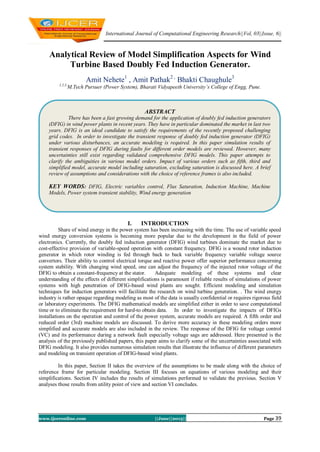
  • 1. International Journal of Computational Engineering Research||Vol, 03||Issue, 6|| www.ijceronline.com ||June||2013|| Page 39 Analytical Review of Model Simplification Aspects for Wind Turbine Based Doubly Fed Induction Generator. Amit Nehete1 , Amit Pathak2 , Bhakti Chaughule3 1,2,3, M.Tech Pursuer (Power System), Bharati Vidyapeeth University’s College of Engg, Pune. I. INTRODUCTION Share of wind energy in the power system has been increasing with the time. The use of variable speed wind energy conversion systems is becoming more popular due to the development in the field of power electronics. Currently, the doubly fed induction generator (DFIG) wind turbines dominate the market due to cost-effective provision of variable-speed operation with constant frequency. DFIG is a wound rotor induction generator in which rotor winding is fed through back to back variable frequency variable voltage source convertors. Their ability to control electrical torque and reactive power offer superior performance concerning system stability. With changing wind speed, one can adjust the frequency of the injected rotor voltage of the DFIG to obtain a constant-frequency at the stator. Adequate modeling of these systems and clear understanding of the effects of different simplifications is paramount if reliable results of simulations of power systems with high penetration of DFIG-based wind plants are sought. Efficient modeling and simulation techniques for induction generators will facilitate the research on wind turbine generation. . The wind energy industry is rather opaque regarding modeling as most of the data is usually confidential or requires rigorous field or laboratory experiments. The DFIG mathematical models are simplified either in order to save computational time or to eliminate the requirement for hard-to obtain data. In order to investigate the impacts of DFIGs installations on the operation and control of the power system, accurate models are required. A fifth order and reduced order (3rd) machine models are discussed. To derive more accuracy in these modeling orders more simplified and accurate models are also included in the review. The response of the DFIG for voltage control (VC) and its performance during a network fault especially voltage sags are addressed. Here presented is the analysis of the previously published papers, this paper aims to clarify some of the uncertainties associated with DFIG modeling. It also provides numerous simulation results that illustrate the influence of different parameters and modeling on transient operation of DFIG-based wind plants. In this paper, Section II takes the overview of the assumptions to be made along with the choice of reference frame for particular modeling. Section III focuses on equations of various modeling and their simplifications. Section IV includes the results of simulations performed to validate the previous. Section V analyses those results from utility point of view and section VI concludes. ABSTRACT There has been a fast growing demand for the application of doubly fed induction generators (DFIG) in wind power plants in recent years. They have in particular dominated the market in last two years. DFIG is an ideal candidate to satisfy the requirements of the recently proposed challenging grid codes. In order to investigate the transient response of doubly fed induction generator (DFIG) under various disturbances, an accurate modeling is required. In this paper simulation results of transient responses of DFIG during faults for different order models are reviewed. However, many uncertainties still exist regarding validated comprehensive DFIG models. This paper attempts to clarify the ambiguities in various model orders. Impact of various orders such as fifth, third and simplified model, accurate model including saturation, excluding saturation is discussed here. A brief review of assumptions and considerations with the choice of reference frames is also included. KEY WORDS: DFIG, Electric variables control, Flux Saturation, Induction Machine, Machine Models, Power system transient stability, Wind energy generation
  • 2. Analytical Review Of Model Simplification… www.ijceronline.com ||June||2013|| Page 40 1.1.Overview of Considerations Three phase stator and rotor windings of an induction machine can be represented by two sets of orthogonal fictious coils. d-q or two axis model for the study of transient behavior has proven to be reliable and accurate. Though rotation of the d-q axis can be arbitrary, three reference speeds i.e reference frames as follows, - The stationary reference frame - the d,q axes do not rotate; - The synchronously rotating reference frame - the d,q axes rotate at synchronous speed; - The rotor reference frame - the d,q axes rotate at rotor speed. Following explains choice of reference frame as elaborated in [9] A. Stationary reference frame When θ = 0; the d, q axes do not rotate therefore it called as stationary reference frame. Also the +d- axis is chosen to coincide with the stator phase A axis. If the bus-bar voltages are … (1) If the motor terminals are directly connected to bus-bar and by using parks transformation … (2) From the above equations; the voltage applied to the stator d-axis coil, is the same as the stator phase A voltage. i.e where Vas is a stator phase A voltage and Vds is stator d-axis coil voltage. This means that the stator d-axis current Ids exactly equal to the phase A current Ias therefore it is not necessary to compute Ias separately at each step of integration process through inverse parks transformation This saves computer time and hence is an advantage of the stationary reference frame. B. Synchronously rotating reference frame When θ = the d, q axes rotate at synchronous speed. Therefore it is called synchronously rotating frame, without any capacitor the terminal voltage changes from eqn ( 2) to …(3) This means that the stator voltages are DC quantities and this has advantages in the field of feedback controller design when the motor equations are linearized around a steady operating point. In this frame we can use larger step length while digital integration; since the variables are slowly changing DC quantities during transient conditions. C. Rotor reference frame When θ = ; The d, q reference frame rotate at rotor speed therefore it is called rotor reference frame, also the d-axis position coincides with the rotor phase A axis. Without any capacitors the terminal voltages changes from eqn (2) … (4) The d, q voltages are therefore of slip frequency and the d-axis rotor current behaves exactly as the phase A rotor current does. This means that it is not necessary to compute the phase A rotor current at each step of the digital integration process through the inverse of Park's transform. This saves computer time and hence is an advantage of the rotor reference frame when studying rotor quantities.The model of an induction generator can have various orders. 5th order model is considered to be a full order model for an induction generator. When fifth i.e full order model is to be used, it demands consideration of differential equations for the whole network as stator circuit is directly connected to the stator circuit. Simplified fifth order doesn’t take into
  • 3. Analytical Review Of Model Simplification… www.ijceronline.com ||June||2013|| Page 41 account certain terms with low weight and employs the FOC algorithm. Third order model excludes stator dynamics reducing the step size for computations. Differential equations of previous order are ignored while developing this stage.In these orders effect of flux saturation is usually given no importance but its inclusion leads to an accurate model.Per unit representation are desirable to be used while analysis as it enables the conversion of whole system to pu quantities on a single power base. II. VARIOUS MODELS OF DFIG A. Fifth order model The references [1][2][3][9] shows the fifth order model of the induction machine in Synchronous reference frame. However in this model effect of main flux and leakage flux is neglected. The equations (5) and (6) gives d and q axis voltages of stator and rotor windings respectively, … (5) … (6) Equation (7) represents stator and rotor flux in d-q synchronous reference frame respectively, … (7) As in [3]voltage behind a transient model for DFIG can be obtained, by defining ed andeq, … (8) And with some manipulations, … (9)
  • 4. Analytical Review Of Model Simplification… www.ijceronline.com ||June||2013|| Page 42 … (10) The electromagnetic torque, … (11) And finally mechanical torque, … (12) These constitute fifth order model which includes stator transients and state variables are stator and rotor flux components and the rotor speed as well. Current components based state space model can possibly be derived by putting stator and rotor flux equations in voltage equations of the same. [1][2][3][5] B. Third order model- Neglecting the rate of change of stator flux linkage is a standard method of reducing the order of the induction generator model. The reduced i.e third order model can be derived by ignoring the differential term in equation (5). Neglecting the stator transients, The reduced order d and q axis stator and rotor voltages, … (13) … (14) When stator transients are neglected (9) can be reduced to, … (15) … (16) The electromagnetic torque,
  • 5. Analytical Review Of Model Simplification… www.ijceronline.com ||June||2013|| Page 43 … (17) In the third order model state variables are two components of the rotor flux linkage and rotor speed. C. Simplified modeling of DFIG- To study behavior of DFIG-based WTs under generic conditions the fifth-order model is popular. But this kind of model raises a complicated system. A complex analysis under transient conditions, the high computational cost of the equation in standards simulators necessitates development of aggregated models. Considering 1) A field-oriented control (FOC) algorithm for the rotor side converter acts as a current source. 2) Synchronous reference frame.Certain low weight components of the equations in the system and the stator electric transient are neglected.Simplified fifth order model enables simplification of some terms of the stator voltage. FOC algorithm regulates dq components of the rotor currents to be injected to the DFIG to perform a decoupled control of the positive sequence of P and Q.Considering the voltage and flux equations of stator and rotor in fifth order model (eq. 5, 6, 7) linear and applying the Laplace transform, the stator currents in the synchronous reference frame are obtained. Some necessary manipulations with abovementioned considerations give the simplified model as in [3], … (18) It can be easily observed that the stator voltage and rotor current appear as input variables. Any variation in the stator voltage will introduce oscillations in the dq components of the stator currents in the synchronous reference frame. Accuracy of the simplified model with respect to the resolution of a fifth order are observed by plotting responses of both systems on same graph as in [3]. D. Accurate model- By reducing the order of the generator computational time can be considerably reduced. Reduced order can be achieved by neglecting differential term in the voltage equations of the machine. [1-4][9] The effect of leakage flux saturation is usually neglected in these papers. In some papers saturation effect is considered but lacks the comparative study among different orders of DFIG model with saturation effect during three phase sag, this is proposed in [4] developing an accurate model. Better representation of the induction machine with saturation under transient condition demands the consideration of variation in the stator and rotor leakage inductances due to saturation in the leakage flux path in saturation effect. To account effect of saturation in leakage flux path, unsaturated stator and rotor leakage reactances in dynamic models in [1-4] are modified by saturation factor K sat. Ksat is introduced as follows, … (19) Where is equal to the ratio between current at which the saturation begins, Isat, to the current through the leakage reactance. [4][6] In [4] a 50% voltage sag is considered for simulation. At t = 5s, a voltage sag happens. Then at t =7s the voltage is restored to its presage value, i.e. 1 pu.
  • 6. Analytical Review Of Model Simplification… www.ijceronline.com ||June||2013|| Page 44 III. RESULTS Simulations carried out to investigate the performance of the DFIG during a system fault in [2]. A fault is applied t=/49.85 s and cleared after 150 ms. a) b) c) d) e) f)
  • 7. Analytical Review Of Model Simplification… www.ijceronline.com ||June||2013|| Page 45 g) h) Fig. 1. Response of DFIG to the system fault (all are in pu) Similar set of results as in fig. 1(a)-(f) for fifth order and third order modeling respectively are obtained for terminal voltage, rotor speed, stator current and electromagnetic torque. Another investigation of the Influence of various models can be seen in [9] as follows, the third and fifth order, modeled in rotor reference frame. Fig. 2(a) DFIG response to a 350 ms short circuit applied at 0s and removed crowbar at 0.5s.
  • 8. Analytical Review Of Model Simplification… www.ijceronline.com ||June||2013|| Page 46 Fig. 2(b) The rotor current response when simulated for 20 % voltage sag with no crowbar operation Behavior of DFIG model under three phase to ground fault, one phase to ground fault, two phase to ground fault with simplified and fifth order model as derived in [2] are as follows, (a) Grid voltage waveforms (b) Active and reactive power (in kVA). (c) isq performance
  • 9. Analytical Review Of Model Simplification… www.ijceronline.com ||June||2013|| Page 47 (d) isd performance Fig. 3.1 Behavior of the DFIG models under three-phase-to-ground faults with the simplified and fifth-order models. (a) Grid voltage waveforms. (b) Active and reactive power (in kVA). (c) isq performance (d) isd performance Fig.3.2 Behavior of the DFIG models under one-phase-to-ground faults with the simplified and fifth-order models.
  • 10. Analytical Review Of Model Simplification… www.ijceronline.com ||June||2013|| Page 48 (a) Grid voltage waveforms. (b) Active and reactive power (in kVA). (c) isq performance (d) isd performance Fig. 3.3 Behavior of the DFIG models under two-phase-to-ground faults with the simplified and fifth-order models. Following figure shows the simulation results obtained in [4] for Torque, ids, iqs, speed for fifth, third and first order model including and excluding saturation effect.
  • 11. Analytical Review Of Model Simplification… www.ijceronline.com ||June||2013|| Page 49 a) b) c) d)
  • 12. Analytical Review Of Model Simplification… www.ijceronline.com ||June||2013|| Page 50 e) f) g) h) Fig. 4 DFIG transient response due to 50% voltage sag. (a) Torque at voltage sag occurrence, (b) torque at voltage recovery, (c) ids at voltage sag occurrence, (d) ids at voltage recovery, (e) iqs at voltage sag occurrence, (f) iqs at voltage recovery, (g) speed at voltage sag occurrence, and (h) speed at voltage recovery
  • 13. Analytical Review Of Model Simplification… www.ijceronline.com ||June||2013|| Page 51 IV. DISCUSSION From the simulations in [2], the rotor current in pu appeared to be very similar to the stator current during the transient. When Machine is operated with increased short term rating of RSC components, the used control strategy and convertor ratings are the factors decide the rotor voltage applied to the DFIG during the network fault. From the fig.1 it can be seen that DFIG response during the fault is more elaborative in the 5th order generator model and includes the transient behavior of the stator current. The 3rd order model though gives a similar mean value of the stator current; details of the transient remain unobserved.In these results Stator flux transients in current, active and reactive power can be clearly traced in fifth order model which is not observed in third order, third order model appears not useful to account for operations of crowbar protection. If DFIG supports reactive power rotor phase A current is higher with fifth order model as seen in 2(a) instead overall peak rotor current is lower as seen in Fig. 2(b). Electrical torque and magnetization of the machine is controlled by q axis and d axis respectively with stator flux oriented reference frame. Fast stator flux change is allowed in third order due to ignored stator flux transients. [3][5] Compared to third order model, Transients in q axis current is higher & d axis current change is small with fifth order model attributes to higher rotor current in third order model. Abrupt stator flux change leads induction of higher rotor current in case of third order and a bit lower rotor current as stator flux change is slower. For three phase fault, sudden reduction in voltage raises lower power injection in network which also has dependency on RSC control during fault. Perfect matching of dynamic performance of simplified model with fifth order model can be clearly observed in the behavior of ids and iqs. Oscillations seen in ids and iqs due to low damping (conditioned by Rs of second order transfer function of eq.18 which is very low in DFIG) in the system. When stator winding is affected by one phase to ground and two phases to ground fault, causes negative sequence voltage translated in 120 Hz oscillations at stator which can be observed higher in second case. Noticeable points in the results are Oscillating Vds which is ignored as its multiplied by lower terms compared to Vqs evidenced the low influence and results of the fifth order are accurately tracked by results of simplified model, precisely describe the dynamic behavior of the DFIG.Fig 4. Shows the simulation results obtained in [4]. At the occurrence of the fault current and torque increases with saturation. Oscillations aren’t observed in third and first order model but noticeably in fifth order model. Difference between Saturation and unsaturated model becomes visible as the order increases, hardly noticed in first order. There isn’t fall in rotor speed for third and first order models but decreases for saturated and unsaturated model of fifth order.After recovery of fault fifth order model appeared faster to reach steady state than third and first order model. Only transient response of speed, torque and current is affected by saturation and not the steady state. Table 1. Simplifications used in different order model Table 1 shows simplifications employed in various modeling orders at a glance [4] V. CONCLUSION If the FOM is used for time-domain simulation, small integration step sizes are required as a result of the small time constants involved. The small integration time step, in addition to the large number of differential equations especially for the grid, results in considerable simulation efforts when studying large systems. These disadvantages limit the applicability of the FOM to small grids. For classical, phasor domain electro-mechanical dynamic studies of large power systems the simplicity and reduced computation time of the 3rd order model appears attractive. For more detailed representations of fault current contribution and investigation of the required ratings of the converters then the 5th order representation may be preferred.Two simple second order transfer functions permit to carry out simulation of large scale wind energy applications. This lead to considerable reduction in computational time as compared to fifth order in simulating behavior of Multiple DFIG. Though complex model can also do, this model appears to be the intuitive estimator for designing strategies of sag response improvement of DFIG.The stator and rotor current of DFIG calculated considering saturation effect are much higher than the values calculated by ignoring it. Rotor speed of saturated model attains steady state value faster as compared to unsaturated models; saturated fifth order reaches faster than others.So saturation effect can be incorporated more importantly to study the transient performance of DFIG and doesn’t prove that much useful for steady state.
  • 14. Analytical Review Of Model Simplification… www.ijceronline.com ||June||2013|| Page 52 REFERENCES [1] Istvan Erlich, Jorg Kretschmann, Jens Fortman, Stephen Mueller-EngelHardt, and Holger Wrede, Modeling of wind turbines based on Doubly-Fed Induction Generator for power system stability studies, IEEE Transactions on Power Systems, VOL 22, No. 3, August 2007. [2] J.B. Ekanayake, L. Holdsworth, N. Jenkins, Comparison of 5th order and 3rd order machine models for doubly fed induction generator (DFIG) wind turbines, Electric Power Systems Research 67 (2003) 207_/215 [3] Alvaro Luna, Francisco Kleber de Araujo Lima, David Santos, Pedro Rodríguez, Edson H. Watanabe, Santiago Arnaltes, Simplified Modeling of a DFIG for Transient Studies in Wind Power Applications, IEEE Transactions on Industrial Electronics, VOL. 58, NO. 1, JANUARY 2011 [4] Alireza abbaszadeh, Saeed lesan, Vahid mortezapour, Transient response of doubly fed induction generator under voltage sag using an accurate model. [5] Pablo Ledesma, Julio Usaola, Effect of Neglecting Stator Transients in Doubly Fed Induction Generators Models, IEEE Transactions on Energy Conversions, VOL. 19, NO. 2, JUNE 2004 [6] Hany M. Jabr, Narayan C. Kar, Effects of main and leakage flux saturation on the transient performances of doubly-fed wind driven induction generator, Electric Power Systems Research 77 (2007) 1019–1027 [7] Andre´s Feijo´o, Jose´ Cidra´s, Camilo Carrillo, A third order model for the doubly-fed induction machine, Electric Power Systems Research 56 (2000) 121–127 [8] R. J. Lee, P. Pillay and R. G. Harley, D,Q Reference Frames for the Simulation of Induction Motors, Electric Power Systems Research, 8 (1984/85) 15 -26 [9] Mustafa Kayikçi and J. V. Milanovic´, Assessing Transient Response of DFIG-Based Wind Plants—The Influence of Model Simplifications and Parameters, IEEE Transactions on Power Systems, VOL. 23, NO. 2, MAY 2008 [10] Zhixin Miao, Lingling Fan, The art of modeling and simulation of induction generator in wind generation applications using high-order model, Simulation Modelling Practice and Theory 16 (2008) 1239–1253 Amit Nehete, M.Tech Electrical-Power System (Pursuing), Department of Electrical Engineering, Bharati Vidhyapeeth University’s College of Engineering, Pune, India. Amit Pathak, M.Tech Electrical-Power System (Pursuing), Department of Electrical Engineering, Bharati Vidhyapeeth University’s College of Engineering, Pune, India. Bhakti Chaughule, M.Tech Electrical-Power System (Pursuing), Department of Electrical Engineering, Bharati Vidhyapeeth University’s College of Engineering, Pune, India.