International Journal of Computational Engineering Research (IJCER) is dedicated to protecting personal information and will make every reasonable effort to handle collected information appropriately. All information collected, as well as related requests, will be handled as carefully and efficiently as possible in accordance with IJCER standards for integrity and objectivity.
1. ISSN (e): 2250 – 3005 || Vol, 04 || Issue, 6 || June – 2014 ||
International Journal of Computational Engineering Research (IJCER)
www.ijceronline.com Open Access Journal Page 50
Design of Wireless to Wired Audio Conversation System
Digambar P. Patil1
, Prof. B. T. Salokhe2
1,
PG Student, 2
, (Associate. Professor) Electronics Dept., TKIET Warananagar, Maharashtra, India
1. INTRODUCTION
PIC microcontroller PIC18F4520 is used in this System. Digital data comes from GSM Modem port
and passes it to the microcontroller for incoming call.GSM Modem continuously sends data from the distant
site. This system is interfaced with a GSM modem. This GSM Modem senses the conditions continuously and
sent signal to the wired unit for incoming call. Incoming call indicated by Buzzer and the received data is
displayed on the LCD. 16X 2 LCD is provided for user interface. After receiving the signal by the
microcontroller it processes the data and sends the read data using keypad to mobile number through GSM
modem. The GSM modem is connected to microcontroller using RS232 interface. Whenever user wants to make
outgoing call, it send signal from wired unit using keypad and LCD to the GSM modem, the GSM modem
receives the data and sends to another subscriber.
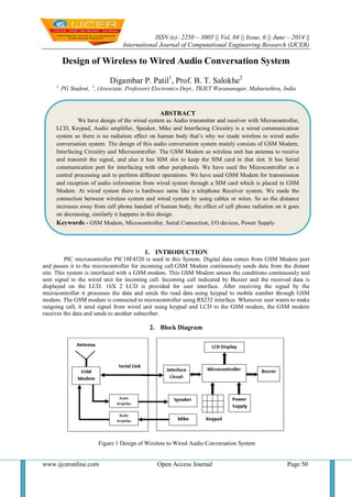
2. Block Diagram
Figure 1 Design of Wireless to Wired Audio Conversation System
ABSTRACT
We have design of the wired system as Audio transmitter and receiver with Microcontroller,
LCD, Keypad, Audio amplifier, Speaker, Mike and Interfacing Circuitry is a wired communication
system so there is no radiation effect on human body that’s why we made wireless to wired audio
conversation system. The design of this audio conversation system mainly consists of GSM Modem,
Interfacing Circuitry and Microcontroller. The GSM Modem as wireless unit has antenna to receive
and transmit the signal, and also it has SIM slot to keep the SIM card in that slot. It has Serial
communication port for interfacing with other peripherals. We have used the Microcontroller as a
central processing unit to perform different operations. We have used GSM Modem for transmission
and reception of audio information from wired system through a SIM card which is placed in GSM
Modem. At wired system there is hardware same like a telephone Receiver system. We made the
connection between wireless system and wired system by using cables or wires. So as the distance
increases away from cell phone handset of human body, the effect of cell phone radiation on it goes
on decreasing, similarly it happens in this design.
Keywords - GSM Modem, Microcontroller, Serial Connection, I/O devices, Power Supply
2. Design of Wireless to Wired…
www.ijceronline.com Open Access Journal Page 51
2.1 Working
This system uses PIC microcontroller PIC18F4520. This system is interfaced with a GSM modem.
RS-232 serial interface is used to transmit and receive the signal from Microcontroller unit and from GSM
Modem.
Since RS232 is not compatible with microcontrollers we need a voltage converter to convert the RS232’s
signals to TTL voltage levels. The MAX 232 converts the RS232 voltage levels to TTL voltage levels and
vice versa.
These are acceptable to the microcontroller’s TxD and RxD pins.
This transceiver data is sensed by the microcontroller and the system continuously monitors the data
condition.
The system monitors the conditions continuously and sends signal to and from SIM to the Microcontroller
unit.
This data is displayed on LCD every time.
for incoming call to the system SIM or user, the GSM modem gets signal through antenna and transmits it
to the Microcontroller via RS-232 serial interface then that signal is displayed on LCD and also buzzer
provides beep indications by Microcontroller. Using ATA Command we can receive this call. This ATA
Command is assigned with “R” button on Keypad. When we push “R” button on keypad the call may get
connected. To disconnect the call we can use ATH Command. For this we can use “H” button on Keypad.
for outgoing call Microcontroller sends data using RS-232 serial interface to the GSM modem using
keypad. Using keypad we can dial a number, it is shown on LCD. After typing a number we can press “C”
button on keypad for calling to other subscriber.
3. GSM Modem
This GSM Modem can accept any GSM network operator SIM card and act just like a mobile phone
with its own unique phone number. Advantage of using this modem will be that you can use its RS232 port to
communicate and develop embedded applications. Applications like SMS Control, data transfer, remote control
and logging can be developed easily. The modem can either be connected to PC serial port directly or to any
microcontroller. It can be used to send and receive SMS or make/receive voice calls. It can also be used in
GPRS mode to connect to internet and do many applications for data logging and control. The Modem is
designed with RS232 Level converter circuitry, which allows you to directly interface PC Serial port .The baud
rate can be configurable from 9600-115200 through AT command. Initially Modem is in Autobaud mode. This
GSM/GPRS RS232 Modem is having internal TCP/IP stack to enable you to connect with internet via GPRS. It
is suitable for SMS as well as DATA transfer application in M2M interface. The modem needed only 3 wires
(Tx, Rx, GND) except Power supply to interface with microcontroller.
3.1 Features of SIM300 GSM Module
Uses the extremely popular SIM300 GSM module
provides the industry standard serial RS232 interface for easy connec
tion to computers and other devices
provides serial TTL interface for easy and direct interface to microcontrollers
Power, RING and Network LEDs for easy debugging
can be controlled through standard AT commands
Module’s operation mode can be co
ntrolled through the PWR Switch connected to the PWR pin
The SIM300 allows an adjustable serial baud rate from 1200 to 115200 bps
Operating Voltage: 7– 15V AC or DC (board has onboard rectifier), Designed for global market, SIM300 is a
Tri-band GSM engine.
Works on frequencies EGSM 900 MHz, DCS 1800 MHz and PCS 1900 MHz
SIM300 can fit almost all the space requirements in your applications, such as smart phone, PDA phone and
other mobile devices.
Supports features like Voice, Data/Fax, SMS, G
PRS and integrated TCP/IP stack.
3. Design of Wireless to Wired…
www.ijceronline.com Open Access Journal Page 52
3.2 Interfaces
RS-232 through D-TYPE 9 pin connector,
Serial port baud rate adjustable 1200 to115200 bps (9600 default)
BRK connector for MIC & SPK, SIM card holder
Power supply through DC socket
SMA antenna c
onnector and Murata Antenna (optional)
LED status of GSM / GPRS module
3.3 AT Commands
AT Commands are used to control a modem. AT means Attention. Every command line starts with “AT”. These
are of two types: Basic and Extended.
ATEO – Echo off
A
TE1- Echo on
Initiating outgoing call:
ATD+mobile number; <enter key>
For disconnecting the active call:
ATH<enter key>
For receiving incoming call:
ATA<enter key>
4. Wired Hardware Unit
This unit has Microcontroller, Keypad, LCD, Speaker, and Microphone. This Microcontroller family
offers the advantages of all PIC18 microcontrollers namely, high computational performance at an economical
price, with the addition of high endurance, Enhanced Flash program memory. On top of these features, the
PIC18F2420/2520/4420/4520 family introduces design enhancements that make these microcontrollers a logical
choice for much high performance, power sensitive applications. The PICkit 2 Development
Programmer/Debugger is a low-cost development programmer. It is capable of programming most of
Microchip’s Flash microcontrollers and serial EEPROM devices. The PICkit 2 unit hardware prevents it from
being powered by the target through the ICSP connector VDD pin. The PIC 18F4520 has 5 usable ports or I/O
registers. These ports are labeled A-E with Ports A-D having 8 bits each and Port E having 4 bits.
4.1 RS 232 Circuit
Since RS232 is not compatible with microcontrollers, we need a voltage converter to convert the RS232’s
signals to TTL voltage levels. These are acceptable to the microcontroller’s TxD and RxD pins. The MAX 232
converts the RS232 voltage levels to TTL voltage levels and vice versa. The chip uses +5V power source which
is the same as the power source for the microcontroller. It provides 2-channel RS232C port and requires external
10uF capacitors.
Figure 2: Interfacing of RS232
4. Design of Wireless to Wired…
www.ijceronline.com Open Access Journal Page 53
5. SOFTWARE TECHNOLOGIES
The software part will consist of: 1. mikroC PRO for PIC 2. Orcad. These two parameters are useful
for programming and drawing the circuits respectively. The mikroC PRO software is used for Programming
code which is to be transplanted into PIC microcontroller and Orcad is used for circuit simulation and layout
design. The mikroC PRO for PIC is a powerful, feature-rich development tool for PIC microcontrollers. It is
designed to provide the programmer with the easiest possible solution to developing applications for embedded
systems, without compromising performance or control. PIC and C fit together well: PIC is the most popular 8-
bit chip in the world, used in a wide variety of applications, and C, prized for its efficiency, is the natural choice
for developing embedded systems. mikroC PRO for PIC provides a successful match featuring highly advanced
IDE, ANSI compliant compiler, broad set of hardware libraries, comprehensive documentation, and plenty of
ready-to-run examples. The fast growing market of embedded systems there is an increasing need to write
application programs in a high-level language such as C. Basically there are two reasons for this trend: programs
for embedded systems become more complex (and hence are difficult to maintain in assembly language), and
processor models for embedded systems have a decreasing lifespan (more frequent re-adapting of applications
to new instruction sets). The code re-usability achieved by C- programming is considered to be a major step
forward in addressing these issues.
5.1 Flowchart of the System:
Figure 3: Flow Chart of System
5. Design of Wireless to Wired…
www.ijceronline.com Open Access Journal Page 54
6. RESULTS
Basically there are three conditions for this system. First, when there is no conversation using this
system, system is Idle. Second, for incoming call to the system SIM or user, the GSM modem gets signal
through antenna and transmits it to the Microcontroller via RS-232 serial cable then that signal is displayed on
LCD and also buzzer provides beep indications by Microcontroller. Third, for outgoing call Microcontroller
sends data using UART and RS-232 serial cable to the GSM modem using keypad to dial the number. In this
way this design is used for audio conversation system.
Figure 4: Descriptive Hardware diagram of the Design
Figure 5: The experimental hardware unit.
6. Design of Wireless to Wired…
www.ijceronline.com Open Access Journal Page 55
Now we can see some results obtained during operation of this conversation system as follows:
Figure 6: The experimental results
At first LCD displays Initial Message. If GSM Modem is not connected to MCU then it shows a message on
LCD as No modem detected. If GSM Modem is connected to MCU then it shows a message as GSM Modem
Ready on LCD. For Outgoing call, dial another subscriber number using keypad. For calling press “C”push
button on Keypad. To end the call press “H” push button on keypad. After call disconnection, again it will
display the initial message on LCD as Welcome to TKIET. For Incoming Call, When another subscriber calling
to the SIM which is placed in our system i.e. to the user of this design then it displays a number of called party
as shown above.
After call disconnection, it may be due to pressing “H”button by user of this system or by another
subscriber in this conversation, LCD displays the same messages as shown in above figures. So these are the
Results of this audio conversation system.
REFERENCES
[1] Vandana Pandya and Deepali Shukla “ GSM Modem Based Data Acquisition System”, International
Journal Of Computational Engineering Research (ijceronline.com) Vol. 2 Issue.5, September 2012
[2] Smt.M.Baby, P.Harini, Y.Eleena Slesser, Y.Tejaswi, K.Ramajyothi, M.Sailaja, K.Annie Sumantha
“SMS based Wireless E-notice board” International Journal of Emerging Technology and Advanced
Engineering, (ISSN 2250-2459, ISO 9001:2008 Certified Journal, Volume 3, Issue 3, March 2013)
[3] Mrs. M.S.Vanjale, Namrata Dokre, Harshad Manekar, Harshal Atwal, “ Gsm Based Water Billing
Machine”, International Journal For Technological Research In Engineering Volume 1, Issue 8, April-
2014
[4] Dr.B.Ramamurthy S.Bhargavi Dr.R.ShashiKumar , “Development of a Low-Cost GSM SMS-Based
Humidity Remote Monitoring and Control system for Industrial Applications”. (IJACSA) International
Journal of Advanced Computer Science and Applications, Vol. 1, No. 4, October 2010
[5] Pankaj Verma, J.S Bhatia, “ Design And Development Of Gps-Gsm based Tracking System With
Googlemap Based Monitoring ” International Journal of Computer Science, Engineering and
Applications, Vol.3, No.3, June 2013
[6] SMS Tutorial –How to use Microsoft hyperterminal to send AT commands
[7] Hardware description of GSM modem simcom300 reference manual