
Recomendados
Mais conteúdo relacionado
Mais procurados
Mais procurados (20)
Destaque
Destaque (10)
Semelhante a Enhancement of the Performance of Hydraulic Power Pack by Increasing Heat Dissipation
Semelhante a Enhancement of the Performance of Hydraulic Power Pack by Increasing Heat Dissipation (20)
Último
Último (20)
Enhancement of the Performance of Hydraulic Power Pack by Increasing Heat Dissipation
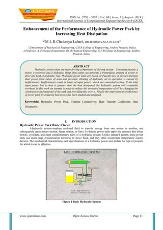
- 1. ISSN (e): 2250 – 3005 || Vol, 04 || Issue, 8 || August– 2014 || International Journal of Computational Engineering Research (IJCER) www.ijceronline.com Open Access Journal Page 13 Enhancement of the Performance of Hydraulic Power Pack by Increasing Heat Dissipation *1M.L.R.Chaitanya Lahari, DR.B.SRINIVASA REDDY2 1,(Department of Mechanical Engineering, G.P.R College of Engineering, Andhra Pradesh, India) 2,Professor & Principal (Department Of Mechanical Engineering, G.P.RCollege of Engineering, Andhra Pradesh, India) I. INTRODUCTION Hydraulic Power Pack Basic Circuit A hydraulic system employs enclosed fluid to transfer energy from one source to another, and subsequently create rotary motion, linear motion, or force. Hydraulic power units apply the pressure that drives motors, cylinders, and other complementary parts of a hydraulic system. Unlike standard pumps, these power units use multi-stage pressurization networks to move fluid, and they often incorporate temperature control devices. The mechanical characteristics and specifications of a hydraulic power unit dictate the type of projects for which it can be effective. Figure 1 Basic Hydraulic System ABSTRACT Hydraulic power units are main driving components of driving system. Consisting mainly a motor, a reservoir and a hydraulic pump these units can generate a tremendous amount of power to drive any kind of hydraulic ram. Hydraulic power units are based on Pascal's law of physics drawing their power from ratios of area and pressure. Heating of hydraulic oil in operation is caused by inefficiencies. Inefficiencies result in losses of input power, which are converted to heat. If the total input power lost to heat is greater than the heat dissipated, the hydraulic system will eventually overheat. In this work an attempt is made to reduce the unwanted temperature of oil by changing the construction and material of the tank and providing fins over it. Finally the improvement of efficiency of power pack by reducing heat losses has been studied and analyzed. Keywords: Hydraulic Power Pack, Thermal Conductivity, Heat Transfer Coefficient, Heat Dissipation
- 2. Enhancement of the Performance of Hydraulic Power Pack by Increasing Heat Dissipation www.ijceronline.com Open Access Journal Page 14 Some of the important factors that influence a hydraulic power unit‟s performance are pressure limits, power capacity, and reservoir volume. In addition, its physical characteristics, including size, power supply, and pumping strength are also significant considerations. To better understand the operating principles and design features in a hydraulic power unit, it may be helpful to look at the basic components of a standard model used in industrial hydraulic systems. As the temperature of hydraulic oil increases, input power falls – and if the total loss of power is greater than the heat dissipated, the hydraulic system will eventually overheat. And if oil overheats, it loses its lubricating properties and increases friction and wear on hydraulic components, meaning hardened seals and increased wear to the system. Another problem caused by high oil temperatures is reduced oil viscosity – which often leads to oil leakages. Because hydraulic components are constructed with very close tolerances, high heat and lubrication loss can also cause severe damage or seizure. Figure 2 Circuit Diagram of Hydraulic Power Pack Repairs can be costly and at worst, operations may have to close down. In many cases it is possible to do without cooling of the power unit because due to the reduced energy consumption the hydraulic fluid will not heat up excessively. This in turn allows a compacter design which reduces complexity and acquisition costs. Reasons for Hydraulic Fluid Cooling: The viscosity of hydraulic oil needs to be suitable during operation for both transmission of power and lubrication. This is very difficult to get right when there is a huge gaping hole between the temperatures of oil at a cold start, say 5°C, and that after continual running at 110°C. It‟s going to be hard to get hold of oil that can manage to perform in that type of scenario. Although seals and hoses are improving in design and materials all the time, they can still operate at their best with a temperature of 82°C before degradation begins. Even just 10°C above that temperature can have a huge effect on their lifespan. Hydraulic oil that gets very hot can suffer from oxidation (air) and hydrolysis (water). This is when there is air and water present in the system. The trouble comes when the temperature rises as according to Arrhenius‟s Law there is an increase in temperature of 10°C and reactions happen considerably faster. In summary, running a hydraulic system at such a high temperature does nothing for its lifespan or performance. It‟s a short cut to degradation and the receipt of several high priced maintenance related invoices. RESERVOIR: The design of the reservoir should be of sufficient capacity to contain all of the fluid in the hydraulic system with at least a 10% excess margin. For static hydraulic transmission systems the reservoir capacity of about 4 x the pump flow/minute should be available. On mobile units it is often necessary to have a smaller reservoir. The return line to the reservoir should be at the furthest end from the pump inlet feed to allow solid particle the drop out and entrained air to be released to the open surface. The return pipe can include a pepper pot arrangement well below the fluid surface level to encourage dispersion of flow. The reservoir should be designed with a safe working level such that the pump inlet and the system return pipe are continuously immersed at all times during the operating cycle. The oil flow through the reservoir should be at a low rate and preferable through perforated baffle plates to encourage air and precipitation of contaminants. The reservoir normally provides a cooling function, often eliminating the need for oil cooler. This chapter estimates the heat dissipated from a reservoir. The construction of the reservoir is generally based on a simple rectangular box with a floor sloping down to a drain plug. The tank should have internal corners suitably designed to ensure convenient cleaning and the surfaces should be desecaled and painted with a paint which is corrosion resistant and suitable for the oil contained. The tank should include a sealed lid which includes a Filler/breather cap with air filter included and a sight level gauge on the side. Fluid power systems must have a sufficient and continuous supply of cool, uncontaminated fluid to operate efficiently. A hydraulic system has a reserve of fluid in addition
- 3. Enhancement of the Performance of Hydraulic Power Pack by Increasing Heat Dissipation www.ijceronline.com Open Access Journal Page 15 to that contained in the other components of the system. This reserve fluid compensates for changing fluid levels from system operation, loss of volume due to cooling and fluid compression from the pressure. This extra fluid is contained in a tank usually called a hydraulic reservoir. Most reservoirs have a capped opening for filling, an air vent, an oil level indicator or dip stick, a return line connection, a pump inlet or suction line connection, a drain line connection, and a drain plug. Figure 3: Reservoir of a Hydraulic Power Pack A properly designed reservoir has internal baffles to prevent excessive sloshing of the fluid and to put a partition between the fluid return line and the pump suction line. The partition forces the returning fluid to travel farther around the tank before being drawn back through the pump inlet line. This does 3 things; it helps cool the fluid more effectively, aids in settling contaminants to the bottom and separates air from the fluid. Larger reservoirs are desirable as all 3 of the above benefits are further enhanced. As a rule of thumb the ideal reservoir will hold about 4 times the pump output per minute. The benefits of a large reservoir are sometimes sacrificed due to space limitations in mobile systems. As a minimum they must be large enough to accommodate thermal expansion of the fluid and changes in fluid level due to system operation. Reservoirs are of two general types - non-pressurized and pressurized. Propower manufactures non-pressurized hydraulic reservoirs and pressurized reservoirs operating up to 5 psi. Most systems are normally designed for equipment operating at normal atmospheric pressure. This includes hydraulic systems for truck or stationary installations. A typical reservoir for use in industrial installations is made of hot rolled steel plates, has welded seams and is not commonly used for mobile operation. The bottom of the reservoir is often convex, and a drain plug is incorporated at the lowest point. Most non-pressurized reservoirs are constructed in a cylindrical shape. The outer housing is manufactured from a strong corrosion-resistant metal. To keep the fluid clean filter elements are normally installed within the reservoir or externally to clean the returning fluid. Reservoirs that are filled by pouring fluid directly into them have a strainer in the filler well to strain out impurities when fluid is added. The quantity of fluid in the reservoir is indicated by a direct reading sight gauge, a clear tube, or a float/dial gauge. Figure 4: MS Tank of a Hydraulic Power Pack
- 4. Enhancement of the Performance of Hydraulic Power Pack by Increasing Heat Dissipation www.ijceronline.com Open Access Journal Page 16 Figure 5: Al Tank of a Hydraulic Power Pack 2. Literature survey: [1] Electric conveyor drives, brush drives, and soft clothe drives have gained a foothold because of the problems traditional hydraulics has caused. Most hydraulic systems in carwashes have used traditional petroleum based mineral oils as hydraulic fluids. Whenever these fluids leaked or a spill occurred it wreaked havoc. Mineral oil must be hand washed from the vehicle surface, brushes and soft clothe must be thoroughly cleaned or replaced, and free mineral oil can harm the water reclaim system. Also mineral oils are flammable and require hazardous storage. Larger spills may necessitate HAZMAT clean up. Mineral oil is not biodegradable and any spillage that winds up in the effluent may result in significant fines. However, the negative effects of mineral oil based hydraulic fluids can and have been rectified by using water based carwash hydraulic lubricants such as MRL Hydraulics‟ ENVIRO-GREEN II®. Now, I am ready to discuss efficiency. There are a number of steps that can be taken to improve hydraulic system efficiencies and improve performance. We need to look at where changes can be made and the impact that they will have on energy efficiencies. If the system upgrade is coupled with a change to water based hydraulic fluid, such as ENVIRO- GREEN II®; the standard hydraulic carwash system becomes more energy efficient and eco-friendly. This becomes much more attractive to already installed systems where the hydraulics is pulled out and replaced with electrics. The conversion can be done with local fluid power and inverter drive professionals. The higher the local energy costs are the more imperative it becomes to make the transition. [2] Fully powered flight controls are common among many aircraft, both military and commercial. Multiple pumps are generally employed to provide these flight controls with a redundant power source in addition to many other aircraft services. The prime hydraulic source in most cases is the engine-driven pump. It is driven directly by one of the aircraft's engines and offers the most efficient method of converting engine horsepower to hydraulic horsepower. The secondary hydraulic power source is generally not as efficient. It must derive its power from a source other than that which powers the prime pump. Present transport aircraft have utilized bleed air, ram air, electrical power, or hydraulic power to drive this redundant pump. All have demonstrated poor power-transfer efficiency when compared to a mechanically coupled pump. This inefficiency generally results in increased cost, weight, and complexity to the aircraft. The inadequate performance of existing hydraulic power transfer units was of particular concern. This paper will address the performance problem as well as the Douglas approach to improve it. [3] With increased focus on the environmental impact of oil-based hydraulic systems, industry ry is seeking new technologies to provide cleaner power transmission sources. Researchers at Purdue University are responding to this demand by studying alternatives such as water hydraulic controls and water-based power transmission. One of the agricultural and biological engineering department's projects involves port design in a composite hydraulic cylinder to reduce cavitations during actuation. Cavitations are when formed and collapse in the hydraulic medium bubbles. This implosion of air bubbles can cause damage within hydraulic components. Purdue has developed a clear plastic cylinder with various port designs to allow capitation visualization during operation. Another university project focuses on developing a gear box with hydrostatic bearings using water as the working fluid. This concept includes using a nonmetallic bearing material. [4] In this era of automation technologies manufacturing sectors have placed very high demands on fast and reliable production methods. This work is the evaluation & analysis of the existing clamping system. The current system uses manual clamping of fixtures for holding the work piece in the proper position while welding process is being done on the part. The evaluated system uses hydraulic vertical swing clamps for holding the work piece driven by hydraulic power pack. Thus the new system achieves automatic and simultaneous clamping of fixtures.
- 5. Enhancement of the Performance of Hydraulic Power Pack by Increasing Heat Dissipation www.ijceronline.com Open Access Journal Page 17 Table 1 Thermal properties of Mild steel and Aluminum Properties units Mild steel Aluminum Density 103kgm-3 7.86 2.70 Thermal Conductivity Jm-1K-1s-1 50 247 Thermal Expansion 10-6K-1 11.7 23.6 Young „Modulus GNm-2 210 71 Tensile Strength J/kg-k 350 310 % Elongation MNm-2 30 14 Temperature readings of hydraulic fluid for mild steel tank and Aluminum tank: S.No Ta(OC) Tmf(OC) ΔT(OC) [ Ta ~ Tmf ] (OC) Talf(OC) ΔT(OC) [ Ta ~ Talf ] (OC) 1 35 35 0 35 0 2 35 39 4 39 4 3 35 41 6 41 6 4 35 44 9 43 9 5 35 46 9 44 9 6 35 49 9 45 10 7 36 50 14 45 9 8 36 50 14 45 9 9 36 51 15 46 9 10 36 52 16 46 9 11 36 52 16 46 9 12 36 52 16 46 9 Ta versus To for MS: Design-Expert® Software Factor Coding: Actual To (deg) Design Points 95% CI Bands X1 = A: Ta Actual Factor B: M = MS A: Ta (deg) 27 29 31 33 35 T o ( d e g ) 20 30 40 50 60 70 80 Warning! Factor involved in AB interaction. 2 One Factor Ta versus To for Aluminum:
- 6. Enhancement of the Performance of Hydraulic Power Pack by Increasing Heat Dissipation www.ijceronline.com Open Access Journal Page 18 Design-Expert® Software Factor Coding: Actual To (deg) Design Points 95% CI Bands X1 = A: Ta Actual Factor B: M = Al A: Ta (deg) 27 29 31 33 35 T o ( d e g ) 20 30 40 50 60 70 80 Warning! Factor involved in AB interaction. 3 One Factor 5. Results & Discussions The total heat transfer rate has been improved by changing the material of the tank from Mild steel to Aluminum for the power pack and the simulation can be done even when the power pack of greater capacity is used. The limitation of the work is that the pressure bearing capacity is more for Mild Steel where the same is less for Aluminum. Interpretation of the work has been analyzed using design expert software and error is only 0.01% where less than 0.05% indicates model terms are significant. REFERENCES [1] Laamanen, A. & Linjama, M. (Eds.) Proceedings of the Third Workshop on Digital Fluid Power, October 13-14, 2010, Tampere, Finland, 170 p. (Tampere University of Technology, 2010) [1] S. S. Ngu, L. C. Kho, T. P. Tan & M. S. Osman, “Design of the Roller Clamp Robotic Assembly”, World Academy of Science, Engineering and Technology, Vol -68, 2012. [2] Tudor Paunescu, “New solutions for driving the hydraulic fixtures”, International Journal of Systems Applications, Engineering & Development, Issue 5, Volume 5, 2011. [3] U. Zuperl, F. Cus & D. Vukelic, “Variable clamping force control for an intelligent fi xturing”, Journal of Production Engineering, Vol-14, February 2011. [4] Emanuele Guglielmino, Claudio Semini, Helmut Kogler, Rudolf Scheidl & Darwin G. Caldwell, “Power Hydraulics - Switched Mode Control of Hydraulic Actuation”, IEEE/RSJ International Conference on Intelligent Robots and Systems on October 18-22, 2010, Taipei, Taiwan. [5] Jeffrey J. Madden, P. Martin, Stowell Peilin, Wu Hongmiao & Li Lu He, “Welding Fixture with Active Position Adapting Functions”, Huohzong Institute of Technology, 7/31/2007. [6] Guohua Qin, “Analysis and Optimal Design of Fixture Clamping Sequence”, Sino-French Laboratory of Concurrent Engineering, Department of Aircraft Manufacturing Engineering, Northwestern Polytechnic University, 482 / Vol. 128, MAY 2006. [7] M. Vural, H.F. Muzafferoglu & U.C. Tapici, “The effect of welding fixtures on welding distortions”, Mechanical Engineering Department, Istanbul Technical [2] Bishop, E. D. Digital Hydraulic Transformer – Approaching Theoretical Perfection in Hydraulic Drive Efficiency. CD-ROM Proceedings of the Ninth Scandinavian International Conference on Fluid Power, June 2-4, 2009, Linköping, Sweden, 19 p. [3] Pugh, B. The Hydraulic Age – Public Power Supplies before Electricity, 176 p. (Mechanical Engineering Publications Ltd., London, 1980) [4] A ldrich, R. H. 1920. Unloading Mechanism. US Patent No 1334828. [5] Rickenberg, F. 1930. Valve. US Patent No. 1757059.
- 7. Enhancement of the Performance of Hydraulic Power Pack by Increasing Heat Dissipation www.ijceronline.com Open Access Journal Page 19 [6] Murphy, R. & Weil, J. 1962. Hydraulic Control System. US Patent No. 3038449. [7] Virvalo, T. 1978. Cylinder Speed Synchronization. Hydraulics & Pneumatics. Dec 1978, pp. 55–57. [8] Ballard, R. L. 1968. System for Minimizing Skidding. US Patent No 3528708. [9] Wennmacher, G. Untersuchung und Anwendung schnellschaltender elektrohydraulischer Ventile für den Einsatz in Kraftfahrzeugen, Dissertation, RWTH Aachen, Germany, 1995. [10] Lauttamus, T., Linjama, M., Nurmia, M. & Vilenius, M. A novel seat valve with reduced axial forces. In: Johnston, D.N. & Edge, K.A. (eds.) Power Transmission and Motion Control, PTMC 2006, 13-15 September, 2006, Bath, UK, pp. 415-427. [11] Johnson, B., Massey, S. & Sturman, O. 2001. Sturman Digital Latching Valve. In: Palmberg, J.-O. (Ed.) The Seventh Scandinavian International Conference on Fluid Power, SICFP‟01, pp. 299–314 (Vol. 3) [12] Anon. PVE Series 4 for PVG 32, PVG 100 and PVG 120, Technical Information. Sauer-Danfoss Prochure No 520L0553 Rev EA, May 2010, 32 p. [13] Suematsu, Y., Yamada, H., Tsukamoto, T. & Muto, T. Digital Control of Electrohydraulic Servo System Operated by Differential Pulse Width Modulation. JSME International Journal, Series C, Vol. 36 (1993), No. 1, pp. 61-68. [14] Becker, U. The Behavior of a Position Controlled Actuator with Switching Valves. Proceedings of the Fourth Scandinavian International Conference on Fluid Power, Sept. 26-29, 1995, Tampere, Finland, pp. 160-167. [15] Muto, T., Yamada, H. & Tsuchiya, S. A Precision Driving System Composed of a Hydraulic Cylinder and High-Speed ON/OFF Valves. Proceedings of the 49th National Conference on Fluid Power, March 19-21, 2002, Las Vegas, Nevada, USA, pp. 627-638. [16] Branson, D. T., Lumkes, J. H. Jr., Wattananithiporn, K. & Fronczak, F. J. Simulated and Experimental Results for a Hydraulic Actuator Controlled by Twl High-Speed On/Off Solenoid Valves. International Journal of Fluid Power, Vol. 9 (2008), No 2, pp. 47- 56. [17] Scheidl R., Riha G., Energy Efficient Switching Control by a Hydraulic „Resonance-Converter‟. In: Burrows, C. R. & Edge K. A. (Eds.): Proc. Workshop on Power Transmission and Motion Control (PTMC‟99), Sept. 8-11, 1999, Bath, UK, pp. 267-273.