SlideShare uma empresa Scribd logo
1 de 8
Baixar para ler offline
Revolving-field analysis of asymmetric
           three-phase machines and its extension to
               single- and two-phase machines
                                                          Bhag Singh Guru

              Indexing terms:     Equivalent circuits, Machine theory, Magnetic flux, Induction motors, Stators

               Abstract: The revolving-field theory as applied to single-phase induction motors is extended to develop a
               concise yet comprehensive theory for asymmetric three-phase induction motors. Each phase is represented by
               its equivalent circuit, not only to allow for uneven direct transformer interactions, due to asymmetric
               locations of phase windings, but also to account for the different number of turns, wire size, winding factor
               etc. each phase may have. The accuracy of the theory was confirmed by actual measurements on symmetric
               and asymmetric three-phase induction motors. Computed and test data on some motors are included for
               illustration. It is also shown that the general three-phase development can be easily applied to determine the
               behaviour of two- and single-phase induction machines, a useful feature for unified computer-aided design, by
               eliminating one and two phase windings, respectively. Not only the procedural details for determining the
               performance of single- and two-phase induction motors are given, but comparisons of numerical and test
               results on some output entities are included as well. Though the comparisons among theoretical and test
               results are made on fractional horsepower motors, the types being built at Universal Electric, the author is
               certain that the development presented here is equally applicable to all sizes of induction motors.


1     Introduction                                                      of suitably chosen components of current and voltage.
                                                                        Further adaptation of this technique to three-phase
A symmetric polyphase induction motor, operating on a                   induction machines with unequal windings and arbitrary
balanced polyphase power supply, is defined as an                       spatial displacements in addition to unbalanced line
induction motor whose windings are evenly displaced in                  voltages may require a large number of voltage and current
space and excited by the currents having the same dis-                  transformations. At this time, such a development, if there
placement in time phase as the windings have in space                   is any, is not known to the author. Another analytical
phase. Consequently, the internal interactions of such an               method would be the direct extension of the revolving-
induction motor are simple, and can be easily characterised             field approach as applied for capacitor motors with
by one primary circuit and a corresponding secondary                    windings not in quadrature.3 Even though this method
circuit based on the revolving-field theory. On the other               requires only three unknown quantities, the torque
hand, the simple crossfield analysis of such motors involves            equation by itself is quite involved.
three times as many circuits as there are phases. Hence the                 All the foregoing methods, in the author's opinion,
polyphase induction motors are universally analysed on the              satisfy only one particular requirement, that is, if the
basis of the revolving-field theory. However, quite often the           development is carried out for a three-phase motor with
stator core punchings designed for a certain pole configur-             asymmetric windings, it would require comprehensive
ation are also used for another pole configuration, and in              changes to make it useful for an asymmetric two-phase
that case, if the number of stator slots per pole pair is not           motor and vice versa. Stated differently, separate computer
a whole number, the phase windings would have to be                     programs are needed to analyse different-phase motors.
arranged at resultant angles other than the conventional                This, in turn, increases the cost of maintaining these
angle for such motors. This results in a spatially unbalanced           programs as 'permanent files' on a time-sharing machine. To
motor even though the windings are identical. The actual                circumvent the situation, we can seek refuge in Kron's
performance of an asymmetric motor is bound to differ                   generalised theory. 4 ' 5 This theory, as Kron states in his
from the conventional motor, and therefore necessitates a               book,s has to be extended further to encompass the entire
different theoretical approach. As far as the author is                 range of asymmetric machines. Moreover, an extension of
aware, no attempt has ever been made in this direction.                 Kron's theory requires the in depth understanding of
Therefore, the primary aim of this paper is to develop a                tensors, symmetrical components, three-phase/two-phase
systematic method for the analysis of asymmetric three-                 and inverse transformations. An average user, however, may
phase induction motors. In addition, the effects of                     not be able to satisfy some or all of these demands.
unbalanced terminal voltages are also included to make the
development more general. However, note that the well                       In literature, almost, all the time, a symmetric three-
known method of symmetrical components1 may be used                     phase induction motor is represented by an analytically
to analyse a symmetric (equal windings) three-phase                     simple yet 'tricky' equivalent circuit. An equivalent circuit,
induction motor running on an unbalanced power supply.                  in the author's opinion, should be based upon the physical
This method has also been extended for the analysis of                  picture as opposed to a 'trick' circuit. In a three-phase
asymmetric two-phase induction machines2 by making use                  motor, the flux produced by one phase induces voltages by
                                                                        direct transformer action in the remaining phases and vice
                                                                        versa. An exact representation of this machine, would
Paper T308 P, first received 9th May and in revised form 24th           require an equivalent circuit for each of its phases and an
November 1978                                                           account for the mutual interactions of the fluxes rather
Dr. Guru is with the Universal Electric Company, 300 East Main
Street, Owosso, Michigan 48867, USA                                     than a single yet tricky circuit. Although the former may

ELECTRIC POWER APPLICATIONS, FEBRUARY 1979, Vol. 2, No. 1                                                                           37
                                                                                                      0140-1327/79/010037 + 08 $01-50/0
increase the number of equations needed for an analytical           displaced at an angle from the r.p.w. can effectively be
solution, it certainly helps the engineer's understanding and      represented by two windings connected in series, one in
thereby enables him to attack more complicated problems            phase with r.p.w., the other in quadrature. The straight-
that he would otherwise hesitate to approach analytically.         forward extension of this principle states that a given set of
This paper therefore represents each winding by its equival-       windings arranged arbitrarily in space can be made fully
ent circuit and then accounts for the direct transformer           equivalent to another arbitrary set of paired quadrature
flux linkages among the windings. Since each phase is rep-         windings. It is, however, obvious that if two or more
resented by its equivalent circuit, the asymmetric three-          windings are in space phase, that is when they are arranged
phase induction motor can be analysed by making use of a           so that their magnetic axes coincide, a direct transformer
simple method published recently.6 By doing so, the final          type of coupling exists between their fluxes. In the present
set of equations are not only useful for analysing symmetric       case, the direct-transformer linkages exist among the fluxes
or asymmetric three-phase motors, but also enable the              of r.p.w. and tf-axis components of the remaining offset
engineer to use them effectively for single- and two-phase         phase windings on one hand, while such coupling exists
induction machines, as will be shown later. Therefore, the         among the fluxes of q-axis components of the offset
present analytical approach does away with the necessity of        windings, on the other. As usual, the voltages are induced in
having separate computer-aided design programs for single-         the main and crossfield axes of the rotor due to trans-
two- and three-phase machines. This in turn considerably           former action and rotation, respectively. Once this concept
reduces the cost of maintaining the 'permanent files' for          is clearly understood, the development of the theory
regular use on a time-sharing computing machine.                   quantitatively is basically simple and straightforward.
    The present method, however, involves the concept that
any given winding can be made equivalent to two mutually            3     Assumptions
orthogonal windings. Although the author employed such
terms as 'd-axis' and 'q-axis' to explain the concept for lack      The following assumptions are imbedded into the theoreti-
of better names, it is different from the so-called ld- g-axis'     cal development that follows in subsequent Sections:
technique used by other authors. The latter applies to the             (a) All the windings follow concentric distribution and
transformation of the voltages and currents while the               therefore, in comparison to the fundamental flux, the
former to the windings. Utilising this concept, each winding        effects of other space-harmonic fluxes are negligible.
of a polyphase motor may be looked upon as two separate                 (b) Friction, windage, and surface losses are all con-
windings mutually perpendicular. However, the two                   sidered to vary as the square of the speed. These losses are
windings have to be assumed to be connected in series               regarded as an extra load on the shaft and are therefore
to have the same effect as the original winding. This               subtracted from the output.
concept is explained further in Section 2. In Section 3,                (c) The magnetic-circuit parameters of the offset phase
some of the basic assumptions generally accepted in motor           windings are all expressed in terms of the magnetic circuit
theory are stated. Section 4 explains the treatment of core         reactances of the reference-phase winding (r.p.w.).
loss. The general theoretical development for three-phase              (d) For direct transformer action, the local mutual
induction motors is presented in Section 5. The systematic          leakage and magnetising fluxes couple perfectly for the
and efficient implementation of this general development            transformed windings both on the d- and the ^r-axes.
 for single- two- and three-phase induction motors is
explained in Section 6. The numerical examples are also             4     Treatment of core loss
 included. Finally, the highlights of this development are          Often, while calculating the performance of an induction
 summarised in Section 7.                                           motor, very approximate methods3 are used to account for
                                                                    the core loss. Since these methods do not interfere with
2     Conceptual background                                         performance equations, they are often acceptable. To be
                                                                    more exact, however, the core loss may be handled by
Since the concept of treating a winding as a set of two             introducing an equivalent resistance, either between rx and
mutually perpendicular windings has already been                    xx as suggested by Trickey,9 or in shunt with the magnet-
published6 most of the details are omitted here. The                ising branch.4 For fractional horsepower motors the author
method of decomposing a winding into two orthogonal                 found no appreciable difference between these two equiv-
windings is needed here to account for uneven direct trans-         alent representations. In this development, however, the
former couplings among mutual fluxes of all the windings,           former method is followed. Even though the equivalent-
since actual windings are not symmetrically arranged. A             resistance concept that accounts for the core loss adds to
summary of the concept is given below.                              the complexity of the performance equations, it does
   If two mutually perpendicular axes, direct axis or d-axis        narrow down the differences between the theoretical and
for short, and quadrature axis or g-axis, are oriented in such      the test results. Also, for large induction motors, the former
a fashion that the axis of one of the three phase-windings          assumption would lead to better correlation between the
coincides with the d-axis, then the positions of the other          theory and tests than the latter.
phase windings can be expressed in terms of electrical
degrees circumferentially offset from the reference-phase
winding (r.p.w.). Thus the flux produced by the r.p.w. has          5     Theory
only a d-axis component while the flux produced by any              In a symmetric three-phase induction motor, the number of
other phase-winding can now be resolved into its com-               turns, wire sizes etc. are the same for each of the three
ponents oriented along d- and ^-axes, respectively. Since           phases and follow identical distribution. Moreover, any two
the flux produced by a winding is a measure of its total            phases are offset circumferentially by 120 electrical degrees
effective conductors, it can likewise be said that the              in space. For the present development, however, let us
winding can be resolved into its components whose axes              consider that the effective number of conductors, wire
coincide with the d- and q-axes. In other words, a winding          sizes etc. are different for each of the phases in addition to
38                                                                ELECTRIC POWER APPLICATIONS, FEBRUAR Y 1979, Vol. 2, No. 1
the arbitrary displacement of the 2nd- and 3rd-phases by 62         ductors for d- and q-axs components of the said phase
and d3 electrical degrees in space with respect to the              windings to the effective number of conductors in the
lst-phase, as shown in Fig. 1. A and B may be defined as            lst-phase winding, respectively, are:
the ratios of effective number of conductors in the 2nd-
and 3rd-phase to the effective number of conductors in the            d-axis component of 2nd-phase: Ad         = Acosd2        (1)
 lst-phase, respectively. If kwl and Nlt Kw2 and N2, and
                                                                      q-axis component of 2nd-phase: Aq         = A sin 62      (2)
kw3 and N3 are the winding factors and the number of
turns for 1st- 2nd- and 3rd-phase, respectively, then A =             d-axis component of 3rd -phase: Bd        = B cos 0 3     (3)
(kw2N2)l(kwlNx)      and B = (kw3N3)/(KwlN1).    It is how-
ever, obvious that for a symmetric motor, kwx = kw2 = kw3,            g-axis component of 3rd phase: BQ = B sin 0 3             (4)
yV, =N2 = N3, d2 = 120° and 0 3 = 2 4 0 ° . In other words,         For an unbalanced three-phase power supply, the magni-
A=B=l.                                                              tude of the voltage may be different for each of the phases.
    To simplify the theoretical development to some extent          Furthermore, each phase may not be 120° apart in time.
but still maintain the generality of the problem, let us            Assuming the lst-phase voltage as a reference, the 2nd- and
consider that the axis of the lst-phase winding coincides           3rd-phase voltages may then be given as:
with the d-axis. This, therefore, is the reference-phase
winding. The 2nd- and 3rd-phase windings can now be                    2nd-phase voltage: V2     = C2Vt exp(jt2)                (5)
decomposed into their d- and q-axis components as
                                                                       3rd-phase voltage: V3 = C 3 K j e x p ( / f 3 )          (6)
shown in Fig. 2. The ratios of effective number of con-
                                                                    where C2, C3 are the constants of proportionality, and t2
                                                                    and t3 are the phase-shifts for the 2nd- and 3rd-phases,
                                                                    respectively, with reference to the lst-phase supply. For a
                                                                    balanced three-phase supply, it is obvious that C2 = C3 —
                                                                    1, t2 — 120° and t3 = 240° in time. The asymmetric three-
                                                                    phase induction motor of Fig. 2 can now be represented by
                                                                    an equivalent circuit. Such a circuit is shown in Fig. 3. The
                                                                    equivalent circuit parameters for the 2nd- and 3rd-phase,
                                                                    respectively, are defined in terms of the lst-phase para-
                                                                    meters and the effective winding ratios. The resistances /y el ,
                                                                    rfe2 and Ayc3, as shown in Fig. 3, are introduced to account
                                                                    for the core loss in each of the three phases. This network
                                                                    representation involves six unknowns. However, by the
                                                                    straightforward application of The"venin's theorem, 8 the
                                                                    equivalent circuit of Fig. 3 may be transformed into
                                                                    another modified equivalent circuit as shown in Fig. 4.
Fig. 1 Asymmetric three-phase induction motor with 2nd- and
Srd-phase windings displaced at d2 and d3 electrical degrees from   Note the terms rm,, rm2 and rm3, and Vml, Vm2 and Vm3.
the lst-phase winding                                               These are the modified resistances and the voltages for the
                                                                    3-phase windings and are given as:
       d -axis
                                                                       r
                                                                       mi       — rpirfei/(rpi                                  (7)
                                                                       v
                                                                           mi   =                                               (8)
                                                                    where the subscript / = 1, 2, or 3 corresponds to 1st- 2nd-
                                                                    or 3rd-phase values of both the resistances and supply
                                                                    voltages, respectively. rpl, rp2, and rp3 are the winding
                                                                    resistances for 1st- 2nd- and 3rd-phase, respectively.
                                                                        As explained earlier, and is now obvious from Fig. 2, in
                                                                    all there are three windings arranged along the d-axis and
                                                                    two windings arranged along the q-axis. Since the currents,
                                                                    as shown in Fig. 4, in all the windings oriented either along
                                                                    the d-axis or the q-axis flow in a sense in the same direction,
                                                                    the mutual interactions among them are considered to be
                                                                    positive. Since the d- and 4-axes are in quadrature, the net
                                                                    flux produced by the windings oriented along one axis, say
                                                                    the d-axis, does not show any direct transformer linkage
                                                                    with the flux produced by the windings concentric with the
                                                                    other axis, ^-axis, and vice versa.
                                               q -axis                  Thus, the voltage induced in the lst-phase winding by its
                                                                    own leakage flux and also by direct transformer coupling of
                                                                    the leakage fluxes of the d-axis components of the 2nd- and
                                                                    3rd-phase windings is
 Fig. 2 Equivalent representation of an asymmetric three-phase
induction motor of Fig. 1                                                              +AdJ2+BdI3)xl                            (9)
The 2nd- and 3rd-phase windings are shown decomposed into d- and    Similarly, the voltages induced in the d-axis components of
(/-axis components                                                  the 2nd- and 3rd-phase windings by the leakage fluxes are
ELECTRIC POWER APPLICATIONS, FEBRUARY 1979, Vol. 2, No. 1                                                                         39
= /(A + AdI2 +      BdI3)Adxx                    (10)              forward:       Ef2d     = (h + AdI2 + BdI3)AdZf     (16)
         = /(A + A dI2 +    BdI3)Bdxx                     00                backward: Eb2d = (/, + AdI2 + BdI3)AdZb             (17)
In a similar manner, the voltages induced in the g-axis                     (b) For the <i-axis component of the 3rd-phase:
components of the 2nd- and 3rd-phase windings by their
leakage fluxes are                                                          forward:       End      = (/, + AdI2 + BdI3)BdZf    (18)

  £», = j(AqI2+BqI3)AqXl                                  (12)              backward: Eb3d          = (/ t + AdI2 + BdI3)BdZb   (19)

  #3<, = j(AqI2+BqI3)BqXl                                 (13)        Similarly, the voltages induced in the g-axis components of
                                                                      the 2nd- and 3rd-phase windings by the forward- and
Voltages induced in the lst-phase by its forward and                  backward-revolving fields set by them, respectively, are:
backward revolving fields as well as by direct transformer               (a) For the q-axis component of the 2nd-phase:
linkage of the two revolving fields set by the d-axis com-
ponents of the 2nd- and 3rd-phase windings are                              forward:       Ef2q     = (AqI2 + BqI3)AQZf         (20)
     forward:   Efld   = (/, +AdI2 + BdI3)Zf              (14)              backward: Eb2q = (AqI2 + BqI3)AqZb                  (21)
     backward: Ebld    = (/, + AdI2 + BdI3)Zb             (15)              (b) For the g-axis component of the 3rd-phase:
Likewise, the voltages induced in the d-axis components of                  forward:       Ef3q     = (AqI2 + BqI3)BqZf         (22)
the 2nd- and 3rd-phase windings by the field components,
                                                                            backward: Eb3q = (Aqf2 + BqI3)BqZb                  (23)
which are set by them as well as by direct transformer
action of the revolving fields set by the lst-phase winding,          We are now in a position to express mathematically the
are:                                                                  speed voltages induced in the d-axis components of the
   (a) For the d-axis component of the 2nd-phase:                     windings by the forward- and backward-revolving fields of


                                                                                                          "fid


                                                                       a.
                                                                       o
                                                                       a


                                                                                     'm2


                                                                                 r
                                                                                 m3


                                                                                                  -3d

                                                                                                        -f3d


                                                                                                        -b3d


                                                         10


 Fig. 3 Equivalent circuit of an asymmetric three-phase induction      Fig. 4    Thevenin 's equivalent of Fig. 3
 motor based upon revolving field theory

40                                                                  ELECTRIC POWER APPLICATIONS, FEBRUAR Y 1979, Vol. 2, No. 1
the g-axis components of the said windings and vice versa.                                         Zl3   = BdZs ~JBQZd           
After some simplifications, the expressions for these
voltages are:
                                                                                                   Z23   = sabzs + JCabZd
                                                                                                   Z31   — BdZs + /BqZd                                     (40c)
   A', =               -j(AqI2+BqI3)Zf                                                    (24)
                                                                                          (25)
                                                                                                   Z32   = SabZ s-jcabzd
   E* =            }(Aqf2+BqI3)Zb
                                                                                                   z33   —   r
                                                                                                             m3   -B2Zs
   E3 = ~KAqI2 +                             BqI3)AdZ,                                    (26)
                                                                                                 with
   lU = j(AqI2 + BqI3)AdZb                                                                (27)
                                                                                                   zd             zb        zs   — Zf ' Zb   T   jx 1       (41)
   Es = -j(Aqf2 + Bqh)BdZf                                                                (28)
                                                                                                   Sab   = AdBc + AqBq               Cab =       AqBd-AdB
                                                                                          (29)
                                                                                                 Once again, eqn. 40a gives the Z-coefficients for single
   £"7 = / ( / , + AdI2 + Bdf3)AqZf                                                       (30)   phase motors, whereas eqns. 40a and 40b are for two-phase
                                                                                                 motors. Needless to say, all the above equations for the
   ^s = " / ( A + ^ d / 2 + BdI3)AqZb                                                     (31)
                                                                                                 Z-parameters are needed for symmetric or asymmetric
   £9 = /(/i + i4 d / 2 + Bdh)BqZf                                                        (32)   three-phase induction machines. Eqns. 37—39 may be
                                                                                                 rewritten in a concise matrix form as
   ff,o = ~J(h + Adh + Bdh)BqZb                                                           (33)
                                                                                                    [Z] M = [V]                                              (42)

Simultaneous equations for the voltages in the three circuits                                    where [Z] is a complex impedance matrix of dimensions
of Fig. 4 can now be written by summing up the voltages in                                       3 x 3 whose elements are given in eqn. 40 in terms of
each of the three stator windings, obtaining                                                     known motor-circuit constants. [/] and [V] are the
                                                                                                 column vectors for the circuit currents and the Thdvenin
   1/        — f. r           + / • ' . . -I- F ,        • + F.. . 4- F 4- P-            f^&   equivalent of the impressed voltages, respectively. The
   'ml           •'I'ml        '   Lj
                                        d    ' '-'fid       ' ^bld   '   lj
                                                                                  1
                                                                                   -'2    Wv     circuit currents can then be determined from the following
                                                                                                 equation:
                   r          +
   Vm2 ~ h m2                      ^2d + Ef2d + ^b2d + E3 + E4
                         2q                                                                         [/] = [ Z p t K ]                                       (43)
                       E-,n    + Ef2q + Eb2q + En + E8                                   (35)
                                                         i   +
                                                                 ^63d + Es + E6                  where [Z]"1 dentoes the inverse of the [Z] matrix.
                                                                 +E9+ E10                (36)       The actual phase currents can now be determined from
                                                         l3q
                                                                                                 the following relation:8

Eqn. 34 is for the referenced-phase winding and can be used                                         Ipi = (Vt + Iirfei)l(rpi + rfei)                         (44)
to analyse a single-phase induction motor running on the                                         for / = 1,2, and 3, respectively.
main winding only, by equating the 2nd- and 3rd-phase                                               The total power input in phase / is given by
currents involved implicitly to zero. Adding eqn. 35, we can
obtain the performance of two-phase symmetric/asymmetric                                                                                                     (45)
motors with balanced/unbalanced terminal voltages at any                                         The forward and backward torques can be calculated
speed of rotation. Remember that a permanent-split capaci-                                       independently for each one of the three phases. This can be
tor motor is only a special case of an unbalanced two-                                           done by calculating the forward and backward voltages
phase induction motor. Further, these equations can also be                                      induced in each of the windings from eqns. 14—33, and
used to determine the locked-rotor torque and the starting                                       multiplying each voltage by the conjugate of the actual
performance of a single-phase induction motor whose                                              current flowing in the winding of concern and using only
auxiliary-phase is disconnected at a predetermined speed. It                                     the real part of the product. Following this procedure, and
is, however, obvious that all the above equations are needed                                     after some simplifications, the torques developed in
to predict the performance of an asymmetric or a sym-                                            synchronous watts for each of the three phases are:
metric three-phase induction motor.
                                                                                                    (a) For the lst-phase:
    By making direct substitutions for the induced voltages,
eqns. 9—33, and after some rearranging, eqns. 34—36 can                                             by forward field: 7>, = Re [IfI?2f]                     (46)
be rewritten in the general form as
                                                                                                    by backward field: Tbl = Re [IbI*Zb]                    (47)
   V          = IZx +I2Z12 + I3Z3                                                     (37)
                                                                                                    (b) For the 2nd-phase:
             =
   V     2       hZ2 +/)Z 2 2 +/3Z23                                                    (38)
                                                                                                    by forward field: 7>2 = Re{/fI2*Zf (Ad +fAq)}           (48)
                                             32          Z33                             (39)
                                                                                                    by backward field: Tb2 = Re {IbI2*Zb (Ad-jAq)}          (49)
where the Z-coefficients are
                                                                                                    (c) For the 3rd-phase:
             = r        +Zs                                                              (40a)
                                                                                                    by forward field: 7} 3 = Kt{IfI*Zf       (Bd + jBq)} (50)
   Zn        - A dZ s              -jAqZd
                                                                                                    by backward field: Tb3 = Re{IbI3*Zb(Bd-jBq)}            (51)
   Z2x =                 AdZs+jAqZd                                                      (40b)
                                                                                                 where the symbol * indicates the conjugate of the com-
   Z72 = rm2              +A2ZS                                                                  plex quantity involved and
ELECTRIC POWER APPLICATIONS, FEBRUARY 1979, Vol. 2, No. 1                                                                                                      41
If = /, + I2 (Ad -jAq) + I3(Bd -jBq)                   (52)        studied in the subsequent paragraphs.
                                                                           In the first example, a typical 230V, 60 Hz, 0-4 h.p.,
     Ib = h+h(Ad+jAQ)+I3(Bd+jBq)                            (53)        4-pole symmetric three-phase induction motor rated at
The overall forward and backward torques developed, in                  1650r/min is considered. The windings in each phase
synchronous watts, including friction and windage losses                consisted of two concentric coils, the inner coil was wound
are:                                       n                            over 6 teeth and had 57 turns, the outer coil was wound
                                                                        over 8 teeth with 76 turns of 24 gauge wire. The per phase
   gross forward torque developed = 7} = £ 7},- (54)
                                                   1= 1
                                                                        values of the motor constants obtained from design con-
                                                    n                   siderations are reproduced below.
      gross backward torque developed = Tb = £            r w (55)
                                                   1=1                     r, + / x , = 12-401 +/5-77412
where « specifies the number of phases. For a three-phase
motor, n = 3.                                                                   rfe = 822-8 £2
   The actual torque developed by the motor, in synchron-                  r2 +jx2   = 5-319+/2-653 ft
ous watts, is
                                                                                xm   = 88-601 ft
      T = Tf-Th                                              (56)
                                                                              F&W = 8-70W
The secondary or the gross output power can be calculated
by multiplying eqn. 56 by the per unit speed of the motor.              The laboratory measurements were taken by connecting the
Subtract the friction and windage losses to obtain the                  motor to a balanced three-phase supply. The test data and
useful power output.                                                    theoretical predictions on various output quantities are
                                                                        given in columns 1 and 2, Table 1. Note that these theoreti-
6       Procedural details                                              cal results in this case can also be obtained by making use
6.1     Three-phase motors
                                                                        of well known equations for symmetric three-phase
                                                                        induction motors based on a single equivalent circuit. It is,
The suggested procedure to predict the performance of                   however, necessary to increase the values of the motor
three-phase induction motors is as follows:                             constants given above by 50%, except for the stator-
    (a) From the known number of turns and the winding                  winding resistances.
factor for each of the three phases, determine A and B.                    A provision was made to add extra windings in series
    (b) From the known locations of the 2nd- and 3rd-phase              with each phase of the above motor to test the motor with
windings with respect to the lst-phase winding, calculate               stator windings having an unequal number of turns. The
the d- and 4-axis components of these windings, using eqns.             tested and computed results, as given in columns 3 and 4 of
1—4. However, for a symmetric motor, set 62 = 120° and                  Table 1, are for a motor with 69 and 92, 66 and 88, and 57
0 3 =240°.                                                              and 76 turns in the inner and the outer coils, for the lst-
    (c) Assuming the lst-phase voltage as a reference, define           2nd- and 3rd- phase windings, respectively.
the 2nd- and 3rd-phase voltages in terms of their magni-                   The last example involves a three-phase induction motor
tudes and time-phase displacements. In other words, define              with unequal turns in each phase and with arbitrary spacing
C2 and C 3 , t2 and t3, respectively. For a balanced three-             of the phases. The number of turns and coils were same as
phase supply, C2 = C3 = 1, and t2 = 120° and t3 = 240°.                 in the previous example, whereas the 2nd- and 3rd- phase
    (d) Calculate Thdvenin's equivalent of resistances and              were displaced at 100 and 200 electrical degress, respect-
voltages by making use of eqns. 7 and 8, respectively.                  ively, from the lst-phase. The measured values and theor-
    (e) From the known constants of the motor, compute                  etical predictions are given in columns 5 and 6, Table 1.
the Z-parameters as given in eqns. 40a, 40b and 40c.                        In all the foregoing cases, as is obvious from Table 1, test
    (/) Use a computer subroutine to invert the complex                 data are in close agreement with theoretical predictions.
impedance [Z] matrix.'                                                  This, therefore, confirms the accuracy of the present
    (g) By making use of eqn. 43, calculate the complex                 method as applied to both symmetric and asymmetric
values of the circuit currents for the modified equivalent              three-phase induction machines.
circuit of Fig. 4.                                                         From eqn. 53, it can readily be shown that for a sym-
    (h) The actual phase currents can now be determined                 metric three-phase supply, the backward field current Ib is
using the relation given in eqn. 44.                                    identically zero. Consequently, there exists no backward-
    (/) Calculate the input power and the gross torques                 revolving field in the motor, as expected at the outset.
developed by the forward and backward fields from eqns.
45—55. The actual torque developed can now be computed                  6.2   Two-phase motors (permanent-split capacitor motors)
from eqn. 56.                                                           In the true sense, there are not that many two-phase
    (/) Determine the forward and backward I2R losses due               induction motors being built toda>. The reason, of course,
to the forward and backward fields by multiplying the                   is that the two-phase power source needed for the normal
forward and backward torques developed by s and 2s,                     operation of such motors is virtually an extinct species.
respectively.                                                           However, a permanent-split capacitor motor may be treated
    (k) Obtain net power developed, total losses, horsepower            as a two-phase motor with unequal windings. The pro-
etc. by employing standard relations.                                   cedure outlined below may be used to determine its
    Since it is not possible to cite all practical possibilities,       performance.
theoretical and test data on three different motors are
                                                                            (i) Calculate A from the known turns and winding factor
                                                                        for each of the two windings. Set B equal to zero.
t A subroutine to solve this matrix is available from the author on         (ii) Use eqns. 1 and 2 to determine the d- and q-
request

42                                                                    ELECTRICPOWER APPLICATIONS, FEBRUARY 1979, Vol. 2, No. 1
Table 1: Theoretical and test results on three-phase, permanent-split capacitor, and single-phase induction motors

               Three-phase motors                                                    Two-phase motors (p.s.c.)                  Single-phase
                                                                                                                                motor
Column         1            2          3           4         5          6            7            8        9         10         11          12
               Test         Theory     Test        Theory Test          Theory       Test         Theory   Test      Theory     Test       Theory

/p..A        1-45             1-476    0-93           0-902   3-21      3221      0-73              0-734    0-76    0-761   0-97      0-960
/ P J ,A     1-47             1-476    0-67           0-678   1-12        1053    0-38              0-383    0-26    0-258   —         -
'P3.A        1-45             1-476    2-10           2085    3 54        3-658   —                 —        —       —       —         —
Pint.™     150 0            156-3     83-7           80-44 172-5        177-5   160-7             160-7    151-7   153-1   181-2     179-7
Pirn.™     1520             156-3     80-3           77-24   84-7        82-85   820               81-57    60-3    59-33    -         -
Pim.W      1515             156-3    240-2          243-1   380-1       384-1     _                 —        —       —       —         —
Pout. W    298-9            3063     255-5          252-5   237-9       235-5   158-6             157-8    139-1   173-7   114-7     112-4
T, kgm       0-1764           0-1808   0-1508         0-149   0-1404      0139    00936             0 0931   00821   00812   0-967S)   00664
Efficiency   0-66             0-65     0-63           0-63    0-37        0-37    0-65              0-65     0-66    0-65    0-63      0-63


components of the 2nd-phase (auxiliary phase for a perma-                        6.3        Single-phase motors
nent-split capacitor motor).
                                                                                 The starting performance of single-phase motors can be
    (iii) Define the magnitude and the phase angle for the                       obtained by using the method explained in Section 6.2,
2nd-phase voltage reference to 1st-phase voltage. In other                       since starting the motor employs both the windings. How-
words, define C2 and t2. For a two-phase motor with                              ever, when the motor is running at its rated speed on the
balanced two-phase terminal voltages, C2 = 1 and t2 = 90°                        main winding only, its performance can be obtained by
(time). However, for a permanent-split capacitor motor                           modifying the procedure of the previous subsection as
(p.s.c.), set C2 = 1 and t2 = 0°.                                                follows:
   (iv) Calculate from eqns. 7 and 8, the The'venin's equiv-                        (a) Determine The'venin's equivalent of resistance and
alent of resistances and voltages. Note that for a p.s.c, the                    the voltage from eqns. 7 and 8, respectively, for the main
capacitor impedance should be added to the auxiliary-                            winding.
winding's resistance for all theoretical purposes except for                        (b) Set I2 = h = 0 and A = B = 0.
obtaining the primary loss for that winding.                                        (c) Compute Zn from eqn. 40a.
    (v) Compute the Z-parameters from eqns. 40a and 40b.
                                                                                    (d) Calculate the current I as follows:
Note that eqn. 40c is not needed in this case because there
are only two-phase windings. Therefore, set/ 3 = 0.                                  A = Vml/Zn
    (vi) Steps (vi)-(xi) are essentially the same as those given
in Section 6.2. Compute the power input, the forward and                         Other quantities of interest can be obtained by following a
 the backward torques with n = 1.                                                similar procedure given in the previous subsections, of
     Two permanent-split capacitor motors were actually built                    course, overlooking nonessential equations.
to verify the accuracy of the present method as extended to                         One of the p.s.c. motors was selected for the testing
two-phase induction motors. One motor was built with an                          purposes as a single-phase induction motor. At its rated
auxiliary winding displaced in quadrature with respect to                        speed, 1650r/min, the auxiliary winding was cut off. The
the main winding, while the other with auxiliary arranged                        test data and the theoretical predictions on various output
at 60 electrical degrees from the main. Since the same                           quantities are given in the last two columns of Table 1. The
windings were used for both motors, the following motor                          feasibility of using the present development to analyse
constants are applicable to either of them:                                      single-phase induction motors running on the main winding
                                                                                 only is indicated by the close relationship between the
           rpx + jxx = 32-255+/ 35-49 ft                                         measured and theoretically predicted values.
                                                                                    Therefore, it can be concluded that a single-analysis
                rn     = 6884-05 ft                                              computer program based on the equations presented in this
                                                                                 paper may be used effectively to analyse single two- and
           r 2 + / x 2 = 36-453+/21-238 ft                                       three-phase induction motors. In addition, the phase
                xm = 735-544 ft                                                  windings may be either equal or unequal, and the spacing
                                                                                 among the phases may be arbitrary.
                   A = 1-32107
                                                                                 7          Conclusions
                rp2 = 135-194ft
                                                                                 This paper provides, first, a basic theory to predict the
    capacitance = 3 05 mF                                                        behaviour of an asymmetric three-phase induction motor
                                                                                 using revolving-field theory, secondly, extensions of the
These 230 V, 60 Hz, 4-pole permanent-split capacitor                             above for single- and two-phase induction motors, and
motors were tested at 1650r/min. The tested and com-                             thirdly, detailed step-by-step analysis procedures for such
puted results on quadrature and nonquadrature motors are                         motors. A computer program was developed based upon
given in Table 1, columns 7 and 8, and 9 and 10, respect-                        the present development and is being used extensively by
ively. It is obvious from these results that the correlation                     the Application Department to analyse such induction
between the tested and computed values is excellent and                          machines as split-phase, permanent-split capacitor with
thereby approves the applicability of the general method to                      either quadrature or nonquadrature windings and sym-
permanent-split capacitor motors, and in turn to other such                      metric or asymmetric three-phase motors. To demonstrate
motors that use two windings for their operation at the                          the effectiveness of the present theoretical approach,
rated speed.                                                                     however, actual measurements and theoretical predictions
ELECTRIC POWER APPLICATIONS, FEBRUARY 1979, Vol. 2, No. 1                                                                                           43
on various output quantities are reported. In each case           9     References
given in this paper, and almost all others not included here,
                                                                  1 FORTESCUE, C. L.: 'Method of symmetrical coordinates
a remarkable correlation exists between theory and actual           applied to the solution of polyphase networks', Trans. Amer.
tests. Needless to say there is a reduction in the cost of          Inst. Electr. Engrs., 1918, 37, pp. 1027-1115
maintaining a single permanent file on a time-sharing             2 LYON, W. V., and KINGSLEY, C. Jun.: 'Analysis of unsym-
system instead of three separate files that otherwise would         metrical machines', ibid., 1936, 55, pp. 471-476
be needed to predict the behaviour of single- two- and            3 PUCHSTEIN, A. F., and LLOYD, T. C: 'Capacitor motors with
                                                                    windings not in quadrature', ibid., 1935, 54, pp. 1235-1239
three-phase induction machines.                                   4 ALGER, P. L.: 'The nature of induction machines' (Gordon and
                                                                    Breach, 1965), chapters 5 and 11
                                                                  5 KRON, G.: 'Equivalent circuits of electrical machinery' (Wiley,
8     Acknowledgments                                               New York, 1951)
                                                                  6 GURU, B. S.: 'Revolving-field analysis of capacitor motors with
The author would like to thank J. Postema for his comments          nonquadrature windings', Electr. Mach. & Electromech., (to be
on the manuscript and for several useful discussions during         published)
the development of this paper. The author is grateful to H.       7 VEINOTT, C. G.: 'Theory and design of small induction motors',
                                                                    (McGraw-Hill, New York, 1959), Chap. 9, pp. 167-175
Penhorwood, Director Engineering Division, for granting           8 GURU, B. S.: 'Two-equation analysis of a capacitor motor by
permission to publish this paper. The author also owes his          cross-field theory', Electr. Mach. & Electromech., 1978, 2, pp.
appreciation to C. Yeiter for expertly typing the manu-              147-153
script and to D. Austin in drafting the Figures for this          9 TRICKEY, P. H.: 'Iron loss calculations on fractional horse-
paper.                                                              power induction motors', Trans. Amer. Inst. Electr. Engrs.,
                                                                      1959,pp. 1663-1669


44                                                              ELECTRIC POWER APPLICATIONS, FEBRUARY 1979, Vol. 2, No. 1

Mais conteúdo relacionado

Mais procurados

Practical of Power System Analysis (PSA)
Practical of Power System Analysis (PSA)Practical of Power System Analysis (PSA)
Practical of Power System Analysis (PSA)Aneel-k Suthar
 
Torque Profiles of Asymmetrically Wound Six-Phase Induction Motor (AWSP-IM) u...
Torque Profiles of Asymmetrically Wound Six-Phase Induction Motor (AWSP-IM) u...Torque Profiles of Asymmetrically Wound Six-Phase Induction Motor (AWSP-IM) u...
Torque Profiles of Asymmetrically Wound Six-Phase Induction Motor (AWSP-IM) u...IOSR Journals
 
Decomposition of current through active power filter for compensating harmoni...
Decomposition of current through active power filter for compensating harmoni...Decomposition of current through active power filter for compensating harmoni...
Decomposition of current through active power filter for compensating harmoni...eSAT Publishing House
 
A New Structure for ''Sen'' Transformer Using Three Winding Linear Transformer
A New Structure for ''Sen'' Transformer Using Three Winding Linear TransformerA New Structure for ''Sen'' Transformer Using Three Winding Linear Transformer
A New Structure for ''Sen'' Transformer Using Three Winding Linear TransformerIJPEDS-IAES
 
EM_2131005_3_phasetransformers
EM_2131005_3_phasetransformersEM_2131005_3_phasetransformers
EM_2131005_3_phasetransformersJitin Pillai
 
SYNCHRONOUS MACHINES BY Dr. P. Kundur Power Systems Solutions
SYNCHRONOUS MACHINES BY Dr. P. Kundur Power Systems SolutionsSYNCHRONOUS MACHINES BY Dr. P. Kundur Power Systems Solutions
SYNCHRONOUS MACHINES BY Dr. P. Kundur Power Systems SolutionsPower System Operation
 
Power System Modelling And Simulation Lab
Power System Modelling And Simulation LabPower System Modelling And Simulation Lab
Power System Modelling And Simulation LabSachin Airan
 
Power System Simulation Laboratory Manual
Power System Simulation Laboratory Manual Power System Simulation Laboratory Manual
Power System Simulation Laboratory Manual Santhosh Kumar
 
Modelling and Simulation of Three Level VSI-Neutral Point Balancing -Fed AC D...
Modelling and Simulation of Three Level VSI-Neutral Point Balancing -Fed AC D...Modelling and Simulation of Three Level VSI-Neutral Point Balancing -Fed AC D...
Modelling and Simulation of Three Level VSI-Neutral Point Balancing -Fed AC D...IJERA Editor
 
3 phase motors 1
3 phase motors 13 phase motors 1
3 phase motors 1popet
 
Modelling of Speed Observer System PPT
Modelling of Speed Observer System PPTModelling of Speed Observer System PPT
Modelling of Speed Observer System PPTSayantan Paul
 
Power Circuits and Transforers-Unit 1 Labvolt Student Manual
Power Circuits and Transforers-Unit 1 Labvolt Student ManualPower Circuits and Transforers-Unit 1 Labvolt Student Manual
Power Circuits and Transforers-Unit 1 Labvolt Student Manualphase3-120A
 

Mais procurados (18)

Practical of Power System Analysis (PSA)
Practical of Power System Analysis (PSA)Practical of Power System Analysis (PSA)
Practical of Power System Analysis (PSA)
 
H06 elo f
H06 elo fH06 elo f
H06 elo f
 
Torque Profiles of Asymmetrically Wound Six-Phase Induction Motor (AWSP-IM) u...
Torque Profiles of Asymmetrically Wound Six-Phase Induction Motor (AWSP-IM) u...Torque Profiles of Asymmetrically Wound Six-Phase Induction Motor (AWSP-IM) u...
Torque Profiles of Asymmetrically Wound Six-Phase Induction Motor (AWSP-IM) u...
 
EMMA IEEE
EMMA IEEEEMMA IEEE
EMMA IEEE
 
Decomposition of current through active power filter for compensating harmoni...
Decomposition of current through active power filter for compensating harmoni...Decomposition of current through active power filter for compensating harmoni...
Decomposition of current through active power filter for compensating harmoni...
 
A New Structure for ''Sen'' Transformer Using Three Winding Linear Transformer
A New Structure for ''Sen'' Transformer Using Three Winding Linear TransformerA New Structure for ''Sen'' Transformer Using Three Winding Linear Transformer
A New Structure for ''Sen'' Transformer Using Three Winding Linear Transformer
 
EM_2131005_3_phasetransformers
EM_2131005_3_phasetransformersEM_2131005_3_phasetransformers
EM_2131005_3_phasetransformers
 
SYNCHRONOUS MACHINES BY Dr. P. Kundur Power Systems Solutions
SYNCHRONOUS MACHINES BY Dr. P. Kundur Power Systems SolutionsSYNCHRONOUS MACHINES BY Dr. P. Kundur Power Systems Solutions
SYNCHRONOUS MACHINES BY Dr. P. Kundur Power Systems Solutions
 
Power System Modelling And Simulation Lab
Power System Modelling And Simulation LabPower System Modelling And Simulation Lab
Power System Modelling And Simulation Lab
 
L36 3ph im
L36 3ph imL36 3ph im
L36 3ph im
 
Power System Simulation Laboratory Manual
Power System Simulation Laboratory Manual Power System Simulation Laboratory Manual
Power System Simulation Laboratory Manual
 
Modelling and Simulation of Three Level VSI-Neutral Point Balancing -Fed AC D...
Modelling and Simulation of Three Level VSI-Neutral Point Balancing -Fed AC D...Modelling and Simulation of Three Level VSI-Neutral Point Balancing -Fed AC D...
Modelling and Simulation of Three Level VSI-Neutral Point Balancing -Fed AC D...
 
3 phase motors 1
3 phase motors 13 phase motors 1
3 phase motors 1
 
Modelling of Speed Observer System PPT
Modelling of Speed Observer System PPTModelling of Speed Observer System PPT
Modelling of Speed Observer System PPT
 
Power System Review
Power System ReviewPower System Review
Power System Review
 
Power Circuits and Transforers-Unit 1 Labvolt Student Manual
Power Circuits and Transforers-Unit 1 Labvolt Student ManualPower Circuits and Transforers-Unit 1 Labvolt Student Manual
Power Circuits and Transforers-Unit 1 Labvolt Student Manual
 
Generator
GeneratorGenerator
Generator
 
Fw3310501057
Fw3310501057Fw3310501057
Fw3310501057
 

Semelhante a Assymetric field revolving

Mathematical Modelling of an 3 Phase Induction Motor Using MATLAB/Simulink
Mathematical Modelling of an 3 Phase Induction Motor Using  MATLAB/Simulink Mathematical Modelling of an 3 Phase Induction Motor Using  MATLAB/Simulink
Mathematical Modelling of an 3 Phase Induction Motor Using MATLAB/Simulink IJMER
 
Modeling and Simulation of Five Phase Induction Motor using MATLAB/Simulink
Modeling and Simulation of Five Phase Induction Motor using MATLAB/SimulinkModeling and Simulation of Five Phase Induction Motor using MATLAB/Simulink
Modeling and Simulation of Five Phase Induction Motor using MATLAB/SimulinkIJERA Editor
 
Performance Evaluation of Self-Excited Cage and Cageless Three Phase Synchron...
Performance Evaluation of Self-Excited Cage and Cageless Three Phase Synchron...Performance Evaluation of Self-Excited Cage and Cageless Three Phase Synchron...
Performance Evaluation of Self-Excited Cage and Cageless Three Phase Synchron...IJERA Editor
 
Total Harmonic Distortion Analysis of a Four Switch 3-Phase Inverter Fed Spee...
Total Harmonic Distortion Analysis of a Four Switch 3-Phase Inverter Fed Spee...Total Harmonic Distortion Analysis of a Four Switch 3-Phase Inverter Fed Spee...
Total Harmonic Distortion Analysis of a Four Switch 3-Phase Inverter Fed Spee...IJPEDS-IAES
 
Detection of Broken Bars in Three Phase Squirrel Cage Induction Motor using F...
Detection of Broken Bars in Three Phase Squirrel Cage Induction Motor using F...Detection of Broken Bars in Three Phase Squirrel Cage Induction Motor using F...
Detection of Broken Bars in Three Phase Squirrel Cage Induction Motor using F...Dr.NAGARAJAN. S
 
Vector Control of Three-Phase Induction Motor with Two Stator Phases Open-Cir...
Vector Control of Three-Phase Induction Motor with Two Stator Phases Open-Cir...Vector Control of Three-Phase Induction Motor with Two Stator Phases Open-Cir...
Vector Control of Three-Phase Induction Motor with Two Stator Phases Open-Cir...IJPEDS-IAES
 
Multiphase Transformer Modelling using Finite Element Method
Multiphase Transformer Modelling using Finite Element MethodMultiphase Transformer Modelling using Finite Element Method
Multiphase Transformer Modelling using Finite Element MethodIAES-IJPEDS
 
Performance Analysis Of Induction Motor For Voltage Mode And Current Mode Con...
Performance Analysis Of Induction Motor For Voltage Mode And Current Mode Con...Performance Analysis Of Induction Motor For Voltage Mode And Current Mode Con...
Performance Analysis Of Induction Motor For Voltage Mode And Current Mode Con...IRJET Journal
 
Speed Control in Electromagnetic Synchronization System with Two Single Phase...
Speed Control in Electromagnetic Synchronization System with Two Single Phase...Speed Control in Electromagnetic Synchronization System with Two Single Phase...
Speed Control in Electromagnetic Synchronization System with Two Single Phase...ijctcm
 
special electrical motor(switched reluctance motor)
special electrical motor(switched reluctance motor)special electrical motor(switched reluctance motor)
special electrical motor(switched reluctance motor)Srihari Datta
 
Speed Control In Electromagnetic Synchronization System With Two Single-phase...
Speed Control In Electromagnetic Synchronization System With Two Single-phase...Speed Control In Electromagnetic Synchronization System With Two Single-phase...
Speed Control In Electromagnetic Synchronization System With Two Single-phase...ijctcm
 
Speed Control In Electromagnetic Synchronization System With Two Singlephase ...
Speed Control In Electromagnetic Synchronization System With Two Singlephase ...Speed Control In Electromagnetic Synchronization System With Two Singlephase ...
Speed Control In Electromagnetic Synchronization System With Two Singlephase ...ijctcm
 
Modelling of Virtual Synchronous Converter for Grid-Inverter Synchronization ...
Modelling of Virtual Synchronous Converter for Grid-Inverter Synchronization ...Modelling of Virtual Synchronous Converter for Grid-Inverter Synchronization ...
Modelling of Virtual Synchronous Converter for Grid-Inverter Synchronization ...IAES-IJPEDS
 

Semelhante a Assymetric field revolving (20)

Mathematical Modelling of an 3 Phase Induction Motor Using MATLAB/Simulink
Mathematical Modelling of an 3 Phase Induction Motor Using  MATLAB/Simulink Mathematical Modelling of an 3 Phase Induction Motor Using  MATLAB/Simulink
Mathematical Modelling of an 3 Phase Induction Motor Using MATLAB/Simulink
 
Modeling and Simulation of Five Phase Induction Motor using MATLAB/Simulink
Modeling and Simulation of Five Phase Induction Motor using MATLAB/SimulinkModeling and Simulation of Five Phase Induction Motor using MATLAB/Simulink
Modeling and Simulation of Five Phase Induction Motor using MATLAB/Simulink
 
Trp sinusoidal
Trp sinusoidalTrp sinusoidal
Trp sinusoidal
 
Performance Evaluation of Self-Excited Cage and Cageless Three Phase Synchron...
Performance Evaluation of Self-Excited Cage and Cageless Three Phase Synchron...Performance Evaluation of Self-Excited Cage and Cageless Three Phase Synchron...
Performance Evaluation of Self-Excited Cage and Cageless Three Phase Synchron...
 
Total Harmonic Distortion Analysis of a Four Switch 3-Phase Inverter Fed Spee...
Total Harmonic Distortion Analysis of a Four Switch 3-Phase Inverter Fed Spee...Total Harmonic Distortion Analysis of a Four Switch 3-Phase Inverter Fed Spee...
Total Harmonic Distortion Analysis of a Four Switch 3-Phase Inverter Fed Spee...
 
Detection of Broken Bars in Three Phase Squirrel Cage Induction Motor using F...
Detection of Broken Bars in Three Phase Squirrel Cage Induction Motor using F...Detection of Broken Bars in Three Phase Squirrel Cage Induction Motor using F...
Detection of Broken Bars in Three Phase Squirrel Cage Induction Motor using F...
 
Vector Control of Three-Phase Induction Motor with Two Stator Phases Open-Cir...
Vector Control of Three-Phase Induction Motor with Two Stator Phases Open-Cir...Vector Control of Three-Phase Induction Motor with Two Stator Phases Open-Cir...
Vector Control of Three-Phase Induction Motor with Two Stator Phases Open-Cir...
 
Ie2514631473
Ie2514631473Ie2514631473
Ie2514631473
 
Ie2514631473
Ie2514631473Ie2514631473
Ie2514631473
 
Multiphase Transformer Modelling using Finite Element Method
Multiphase Transformer Modelling using Finite Element MethodMultiphase Transformer Modelling using Finite Element Method
Multiphase Transformer Modelling using Finite Element Method
 
Ce33493496
Ce33493496Ce33493496
Ce33493496
 
Ce33493496
Ce33493496Ce33493496
Ce33493496
 
Performance Analysis Of Induction Motor For Voltage Mode And Current Mode Con...
Performance Analysis Of Induction Motor For Voltage Mode And Current Mode Con...Performance Analysis Of Induction Motor For Voltage Mode And Current Mode Con...
Performance Analysis Of Induction Motor For Voltage Mode And Current Mode Con...
 
Speed Control in Electromagnetic Synchronization System with Two Single Phase...
Speed Control in Electromagnetic Synchronization System with Two Single Phase...Speed Control in Electromagnetic Synchronization System with Two Single Phase...
Speed Control in Electromagnetic Synchronization System with Two Single Phase...
 
special electrical motor(switched reluctance motor)
special electrical motor(switched reluctance motor)special electrical motor(switched reluctance motor)
special electrical motor(switched reluctance motor)
 
Speed Control In Electromagnetic Synchronization System With Two Single-phase...
Speed Control In Electromagnetic Synchronization System With Two Single-phase...Speed Control In Electromagnetic Synchronization System With Two Single-phase...
Speed Control In Electromagnetic Synchronization System With Two Single-phase...
 
Speed Control In Electromagnetic Synchronization System With Two Singlephase ...
Speed Control In Electromagnetic Synchronization System With Two Singlephase ...Speed Control In Electromagnetic Synchronization System With Two Singlephase ...
Speed Control In Electromagnetic Synchronization System With Two Singlephase ...
 
[IJET-V1I4P8] Authors :T.Vignesh,V.Dileepan, P.Kannappar, R.Manoj Babu , P.E...
[IJET-V1I4P8]  Authors :T.Vignesh,V.Dileepan, P.Kannappar, R.Manoj Babu , P.E...[IJET-V1I4P8]  Authors :T.Vignesh,V.Dileepan, P.Kannappar, R.Manoj Babu , P.E...
[IJET-V1I4P8] Authors :T.Vignesh,V.Dileepan, P.Kannappar, R.Manoj Babu , P.E...
 
Modelling of Virtual Synchronous Converter for Grid-Inverter Synchronization ...
Modelling of Virtual Synchronous Converter for Grid-Inverter Synchronization ...Modelling of Virtual Synchronous Converter for Grid-Inverter Synchronization ...
Modelling of Virtual Synchronous Converter for Grid-Inverter Synchronization ...
 
Synchro
SynchroSynchro
Synchro
 

Mais de Hari Prasath

Voltage and power quality control in wind power applications by svc
Voltage and power quality control in wind power applications by svcVoltage and power quality control in wind power applications by svc
Voltage and power quality control in wind power applications by svcHari Prasath
 
Solar charger with parallel resonant
Solar charger with parallel resonantSolar charger with parallel resonant
Solar charger with parallel resonantHari Prasath
 
Solar battery design
Solar battery designSolar battery design
Solar battery designHari Prasath
 
Railway rectification
Railway rectificationRailway rectification
Railway rectificationHari Prasath
 
Power control by fuzzy logic
Power control by fuzzy logicPower control by fuzzy logic
Power control by fuzzy logicHari Prasath
 
Economical stepper motor
Economical stepper motorEconomical stepper motor
Economical stepper motorHari Prasath
 
Battery charging and backup
Battery charging and backupBattery charging and backup
Battery charging and backupHari Prasath
 
Windenergy utilisation
Windenergy utilisationWindenergy utilisation
Windenergy utilisationHari Prasath
 

Mais de Hari Prasath (9)

Voltage and power quality control in wind power applications by svc
Voltage and power quality control in wind power applications by svcVoltage and power quality control in wind power applications by svc
Voltage and power quality control in wind power applications by svc
 
Solar charger with parallel resonant
Solar charger with parallel resonantSolar charger with parallel resonant
Solar charger with parallel resonant
 
Solar battery design
Solar battery designSolar battery design
Solar battery design
 
Railway rectification
Railway rectificationRailway rectification
Railway rectification
 
Power control by fuzzy logic
Power control by fuzzy logicPower control by fuzzy logic
Power control by fuzzy logic
 
Electric scooter
Electric scooterElectric scooter
Electric scooter
 
Economical stepper motor
Economical stepper motorEconomical stepper motor
Economical stepper motor
 
Battery charging and backup
Battery charging and backupBattery charging and backup
Battery charging and backup
 
Windenergy utilisation
Windenergy utilisationWindenergy utilisation
Windenergy utilisation
 

Último

Unit-V; Pricing (Pharma Marketing Management).pptx
Unit-V; Pricing (Pharma Marketing Management).pptxUnit-V; Pricing (Pharma Marketing Management).pptx
Unit-V; Pricing (Pharma Marketing Management).pptxVishalSingh1417
 
Interdisciplinary_Insights_Data_Collection_Methods.pptx
Interdisciplinary_Insights_Data_Collection_Methods.pptxInterdisciplinary_Insights_Data_Collection_Methods.pptx
Interdisciplinary_Insights_Data_Collection_Methods.pptxPooja Bhuva
 
Fostering Friendships - Enhancing Social Bonds in the Classroom
Fostering Friendships - Enhancing Social Bonds  in the ClassroomFostering Friendships - Enhancing Social Bonds  in the Classroom
Fostering Friendships - Enhancing Social Bonds in the ClassroomPooky Knightsmith
 
FSB Advising Checklist - Orientation 2024
FSB Advising Checklist - Orientation 2024FSB Advising Checklist - Orientation 2024
FSB Advising Checklist - Orientation 2024Elizabeth Walsh
 
Sociology 101 Demonstration of Learning Exhibit
Sociology 101 Demonstration of Learning ExhibitSociology 101 Demonstration of Learning Exhibit
Sociology 101 Demonstration of Learning Exhibitjbellavia9
 
How to Create and Manage Wizard in Odoo 17
How to Create and Manage Wizard in Odoo 17How to Create and Manage Wizard in Odoo 17
How to Create and Manage Wizard in Odoo 17Celine George
 
General Principles of Intellectual Property: Concepts of Intellectual Proper...
General Principles of Intellectual Property: Concepts of Intellectual  Proper...General Principles of Intellectual Property: Concepts of Intellectual  Proper...
General Principles of Intellectual Property: Concepts of Intellectual Proper...Poonam Aher Patil
 
HMCS Max Bernays Pre-Deployment Brief (May 2024).pptx
HMCS Max Bernays Pre-Deployment Brief (May 2024).pptxHMCS Max Bernays Pre-Deployment Brief (May 2024).pptx
HMCS Max Bernays Pre-Deployment Brief (May 2024).pptxEsquimalt MFRC
 
ICT Role in 21st Century Education & its Challenges.pptx
ICT Role in 21st Century Education & its Challenges.pptxICT Role in 21st Century Education & its Challenges.pptx
ICT Role in 21st Century Education & its Challenges.pptxAreebaZafar22
 
Jual Obat Aborsi Hongkong ( Asli No.1 ) 085657271886 Obat Penggugur Kandungan...
Jual Obat Aborsi Hongkong ( Asli No.1 ) 085657271886 Obat Penggugur Kandungan...Jual Obat Aborsi Hongkong ( Asli No.1 ) 085657271886 Obat Penggugur Kandungan...
Jual Obat Aborsi Hongkong ( Asli No.1 ) 085657271886 Obat Penggugur Kandungan...ZurliaSoop
 
TỔNG ÔN TẬP THI VÀO LỚP 10 MÔN TIẾNG ANH NĂM HỌC 2023 - 2024 CÓ ĐÁP ÁN (NGỮ Â...
TỔNG ÔN TẬP THI VÀO LỚP 10 MÔN TIẾNG ANH NĂM HỌC 2023 - 2024 CÓ ĐÁP ÁN (NGỮ Â...TỔNG ÔN TẬP THI VÀO LỚP 10 MÔN TIẾNG ANH NĂM HỌC 2023 - 2024 CÓ ĐÁP ÁN (NGỮ Â...
TỔNG ÔN TẬP THI VÀO LỚP 10 MÔN TIẾNG ANH NĂM HỌC 2023 - 2024 CÓ ĐÁP ÁN (NGỮ Â...Nguyen Thanh Tu Collection
 
Kodo Millet PPT made by Ghanshyam bairwa college of Agriculture kumher bhara...
Kodo Millet  PPT made by Ghanshyam bairwa college of Agriculture kumher bhara...Kodo Millet  PPT made by Ghanshyam bairwa college of Agriculture kumher bhara...
Kodo Millet PPT made by Ghanshyam bairwa college of Agriculture kumher bhara...pradhanghanshyam7136
 
ICT role in 21st century education and it's challenges.
ICT role in 21st century education and it's challenges.ICT role in 21st century education and it's challenges.
ICT role in 21st century education and it's challenges.MaryamAhmad92
 
Single or Multiple melodic lines structure
Single or Multiple melodic lines structureSingle or Multiple melodic lines structure
Single or Multiple melodic lines structuredhanjurrannsibayan2
 
Spellings Wk 3 English CAPS CARES Please Practise
Spellings Wk 3 English CAPS CARES Please PractiseSpellings Wk 3 English CAPS CARES Please Practise
Spellings Wk 3 English CAPS CARES Please PractiseAnaAcapella
 
SOC 101 Demonstration of Learning Presentation
SOC 101 Demonstration of Learning PresentationSOC 101 Demonstration of Learning Presentation
SOC 101 Demonstration of Learning Presentationcamerronhm
 
80 ĐỀ THI THỬ TUYỂN SINH TIẾNG ANH VÀO 10 SỞ GD – ĐT THÀNH PHỐ HỒ CHÍ MINH NĂ...
80 ĐỀ THI THỬ TUYỂN SINH TIẾNG ANH VÀO 10 SỞ GD – ĐT THÀNH PHỐ HỒ CHÍ MINH NĂ...80 ĐỀ THI THỬ TUYỂN SINH TIẾNG ANH VÀO 10 SỞ GD – ĐT THÀNH PHỐ HỒ CHÍ MINH NĂ...
80 ĐỀ THI THỬ TUYỂN SINH TIẾNG ANH VÀO 10 SỞ GD – ĐT THÀNH PHỐ HỒ CHÍ MINH NĂ...Nguyen Thanh Tu Collection
 
Key note speaker Neum_Admir Softic_ENG.pdf
Key note speaker Neum_Admir Softic_ENG.pdfKey note speaker Neum_Admir Softic_ENG.pdf
Key note speaker Neum_Admir Softic_ENG.pdfAdmir Softic
 
SKILL OF INTRODUCING THE LESSON MICRO SKILLS.pptx
SKILL OF INTRODUCING THE LESSON MICRO SKILLS.pptxSKILL OF INTRODUCING THE LESSON MICRO SKILLS.pptx
SKILL OF INTRODUCING THE LESSON MICRO SKILLS.pptxAmanpreet Kaur
 

Último (20)

Unit-V; Pricing (Pharma Marketing Management).pptx
Unit-V; Pricing (Pharma Marketing Management).pptxUnit-V; Pricing (Pharma Marketing Management).pptx
Unit-V; Pricing (Pharma Marketing Management).pptx
 
Interdisciplinary_Insights_Data_Collection_Methods.pptx
Interdisciplinary_Insights_Data_Collection_Methods.pptxInterdisciplinary_Insights_Data_Collection_Methods.pptx
Interdisciplinary_Insights_Data_Collection_Methods.pptx
 
Fostering Friendships - Enhancing Social Bonds in the Classroom
Fostering Friendships - Enhancing Social Bonds  in the ClassroomFostering Friendships - Enhancing Social Bonds  in the Classroom
Fostering Friendships - Enhancing Social Bonds in the Classroom
 
FSB Advising Checklist - Orientation 2024
FSB Advising Checklist - Orientation 2024FSB Advising Checklist - Orientation 2024
FSB Advising Checklist - Orientation 2024
 
Sociology 101 Demonstration of Learning Exhibit
Sociology 101 Demonstration of Learning ExhibitSociology 101 Demonstration of Learning Exhibit
Sociology 101 Demonstration of Learning Exhibit
 
How to Create and Manage Wizard in Odoo 17
How to Create and Manage Wizard in Odoo 17How to Create and Manage Wizard in Odoo 17
How to Create and Manage Wizard in Odoo 17
 
General Principles of Intellectual Property: Concepts of Intellectual Proper...
General Principles of Intellectual Property: Concepts of Intellectual  Proper...General Principles of Intellectual Property: Concepts of Intellectual  Proper...
General Principles of Intellectual Property: Concepts of Intellectual Proper...
 
HMCS Max Bernays Pre-Deployment Brief (May 2024).pptx
HMCS Max Bernays Pre-Deployment Brief (May 2024).pptxHMCS Max Bernays Pre-Deployment Brief (May 2024).pptx
HMCS Max Bernays Pre-Deployment Brief (May 2024).pptx
 
ICT Role in 21st Century Education & its Challenges.pptx
ICT Role in 21st Century Education & its Challenges.pptxICT Role in 21st Century Education & its Challenges.pptx
ICT Role in 21st Century Education & its Challenges.pptx
 
Jual Obat Aborsi Hongkong ( Asli No.1 ) 085657271886 Obat Penggugur Kandungan...
Jual Obat Aborsi Hongkong ( Asli No.1 ) 085657271886 Obat Penggugur Kandungan...Jual Obat Aborsi Hongkong ( Asli No.1 ) 085657271886 Obat Penggugur Kandungan...
Jual Obat Aborsi Hongkong ( Asli No.1 ) 085657271886 Obat Penggugur Kandungan...
 
TỔNG ÔN TẬP THI VÀO LỚP 10 MÔN TIẾNG ANH NĂM HỌC 2023 - 2024 CÓ ĐÁP ÁN (NGỮ Â...
TỔNG ÔN TẬP THI VÀO LỚP 10 MÔN TIẾNG ANH NĂM HỌC 2023 - 2024 CÓ ĐÁP ÁN (NGỮ Â...TỔNG ÔN TẬP THI VÀO LỚP 10 MÔN TIẾNG ANH NĂM HỌC 2023 - 2024 CÓ ĐÁP ÁN (NGỮ Â...
TỔNG ÔN TẬP THI VÀO LỚP 10 MÔN TIẾNG ANH NĂM HỌC 2023 - 2024 CÓ ĐÁP ÁN (NGỮ Â...
 
Kodo Millet PPT made by Ghanshyam bairwa college of Agriculture kumher bhara...
Kodo Millet  PPT made by Ghanshyam bairwa college of Agriculture kumher bhara...Kodo Millet  PPT made by Ghanshyam bairwa college of Agriculture kumher bhara...
Kodo Millet PPT made by Ghanshyam bairwa college of Agriculture kumher bhara...
 
Spatium Project Simulation student brief
Spatium Project Simulation student briefSpatium Project Simulation student brief
Spatium Project Simulation student brief
 
ICT role in 21st century education and it's challenges.
ICT role in 21st century education and it's challenges.ICT role in 21st century education and it's challenges.
ICT role in 21st century education and it's challenges.
 
Single or Multiple melodic lines structure
Single or Multiple melodic lines structureSingle or Multiple melodic lines structure
Single or Multiple melodic lines structure
 
Spellings Wk 3 English CAPS CARES Please Practise
Spellings Wk 3 English CAPS CARES Please PractiseSpellings Wk 3 English CAPS CARES Please Practise
Spellings Wk 3 English CAPS CARES Please Practise
 
SOC 101 Demonstration of Learning Presentation
SOC 101 Demonstration of Learning PresentationSOC 101 Demonstration of Learning Presentation
SOC 101 Demonstration of Learning Presentation
 
80 ĐỀ THI THỬ TUYỂN SINH TIẾNG ANH VÀO 10 SỞ GD – ĐT THÀNH PHỐ HỒ CHÍ MINH NĂ...
80 ĐỀ THI THỬ TUYỂN SINH TIẾNG ANH VÀO 10 SỞ GD – ĐT THÀNH PHỐ HỒ CHÍ MINH NĂ...80 ĐỀ THI THỬ TUYỂN SINH TIẾNG ANH VÀO 10 SỞ GD – ĐT THÀNH PHỐ HỒ CHÍ MINH NĂ...
80 ĐỀ THI THỬ TUYỂN SINH TIẾNG ANH VÀO 10 SỞ GD – ĐT THÀNH PHỐ HỒ CHÍ MINH NĂ...
 
Key note speaker Neum_Admir Softic_ENG.pdf
Key note speaker Neum_Admir Softic_ENG.pdfKey note speaker Neum_Admir Softic_ENG.pdf
Key note speaker Neum_Admir Softic_ENG.pdf
 
SKILL OF INTRODUCING THE LESSON MICRO SKILLS.pptx
SKILL OF INTRODUCING THE LESSON MICRO SKILLS.pptxSKILL OF INTRODUCING THE LESSON MICRO SKILLS.pptx
SKILL OF INTRODUCING THE LESSON MICRO SKILLS.pptx
 

Assymetric field revolving

  • 1. Revolving-field analysis of asymmetric three-phase machines and its extension to single- and two-phase machines Bhag Singh Guru Indexing terms: Equivalent circuits, Machine theory, Magnetic flux, Induction motors, Stators Abstract: The revolving-field theory as applied to single-phase induction motors is extended to develop a concise yet comprehensive theory for asymmetric three-phase induction motors. Each phase is represented by its equivalent circuit, not only to allow for uneven direct transformer interactions, due to asymmetric locations of phase windings, but also to account for the different number of turns, wire size, winding factor etc. each phase may have. The accuracy of the theory was confirmed by actual measurements on symmetric and asymmetric three-phase induction motors. Computed and test data on some motors are included for illustration. It is also shown that the general three-phase development can be easily applied to determine the behaviour of two- and single-phase induction machines, a useful feature for unified computer-aided design, by eliminating one and two phase windings, respectively. Not only the procedural details for determining the performance of single- and two-phase induction motors are given, but comparisons of numerical and test results on some output entities are included as well. Though the comparisons among theoretical and test results are made on fractional horsepower motors, the types being built at Universal Electric, the author is certain that the development presented here is equally applicable to all sizes of induction motors. 1 Introduction of suitably chosen components of current and voltage. Further adaptation of this technique to three-phase A symmetric polyphase induction motor, operating on a induction machines with unequal windings and arbitrary balanced polyphase power supply, is defined as an spatial displacements in addition to unbalanced line induction motor whose windings are evenly displaced in voltages may require a large number of voltage and current space and excited by the currents having the same dis- transformations. At this time, such a development, if there placement in time phase as the windings have in space is any, is not known to the author. Another analytical phase. Consequently, the internal interactions of such an method would be the direct extension of the revolving- induction motor are simple, and can be easily characterised field approach as applied for capacitor motors with by one primary circuit and a corresponding secondary windings not in quadrature.3 Even though this method circuit based on the revolving-field theory. On the other requires only three unknown quantities, the torque hand, the simple crossfield analysis of such motors involves equation by itself is quite involved. three times as many circuits as there are phases. Hence the All the foregoing methods, in the author's opinion, polyphase induction motors are universally analysed on the satisfy only one particular requirement, that is, if the basis of the revolving-field theory. However, quite often the development is carried out for a three-phase motor with stator core punchings designed for a certain pole configur- asymmetric windings, it would require comprehensive ation are also used for another pole configuration, and in changes to make it useful for an asymmetric two-phase that case, if the number of stator slots per pole pair is not motor and vice versa. Stated differently, separate computer a whole number, the phase windings would have to be programs are needed to analyse different-phase motors. arranged at resultant angles other than the conventional This, in turn, increases the cost of maintaining these angle for such motors. This results in a spatially unbalanced programs as 'permanent files' on a time-sharing machine. To motor even though the windings are identical. The actual circumvent the situation, we can seek refuge in Kron's performance of an asymmetric motor is bound to differ generalised theory. 4 ' 5 This theory, as Kron states in his from the conventional motor, and therefore necessitates a book,s has to be extended further to encompass the entire different theoretical approach. As far as the author is range of asymmetric machines. Moreover, an extension of aware, no attempt has ever been made in this direction. Kron's theory requires the in depth understanding of Therefore, the primary aim of this paper is to develop a tensors, symmetrical components, three-phase/two-phase systematic method for the analysis of asymmetric three- and inverse transformations. An average user, however, may phase induction motors. In addition, the effects of not be able to satisfy some or all of these demands. unbalanced terminal voltages are also included to make the development more general. However, note that the well In literature, almost, all the time, a symmetric three- known method of symmetrical components1 may be used phase induction motor is represented by an analytically to analyse a symmetric (equal windings) three-phase simple yet 'tricky' equivalent circuit. An equivalent circuit, induction motor running on an unbalanced power supply. in the author's opinion, should be based upon the physical This method has also been extended for the analysis of picture as opposed to a 'trick' circuit. In a three-phase asymmetric two-phase induction machines2 by making use motor, the flux produced by one phase induces voltages by direct transformer action in the remaining phases and vice versa. An exact representation of this machine, would Paper T308 P, first received 9th May and in revised form 24th require an equivalent circuit for each of its phases and an November 1978 account for the mutual interactions of the fluxes rather Dr. Guru is with the Universal Electric Company, 300 East Main Street, Owosso, Michigan 48867, USA than a single yet tricky circuit. Although the former may ELECTRIC POWER APPLICATIONS, FEBRUARY 1979, Vol. 2, No. 1 37 0140-1327/79/010037 + 08 $01-50/0
  • 2. increase the number of equations needed for an analytical displaced at an angle from the r.p.w. can effectively be solution, it certainly helps the engineer's understanding and represented by two windings connected in series, one in thereby enables him to attack more complicated problems phase with r.p.w., the other in quadrature. The straight- that he would otherwise hesitate to approach analytically. forward extension of this principle states that a given set of This paper therefore represents each winding by its equival- windings arranged arbitrarily in space can be made fully ent circuit and then accounts for the direct transformer equivalent to another arbitrary set of paired quadrature flux linkages among the windings. Since each phase is rep- windings. It is, however, obvious that if two or more resented by its equivalent circuit, the asymmetric three- windings are in space phase, that is when they are arranged phase induction motor can be analysed by making use of a so that their magnetic axes coincide, a direct transformer simple method published recently.6 By doing so, the final type of coupling exists between their fluxes. In the present set of equations are not only useful for analysing symmetric case, the direct-transformer linkages exist among the fluxes or asymmetric three-phase motors, but also enable the of r.p.w. and tf-axis components of the remaining offset engineer to use them effectively for single- and two-phase phase windings on one hand, while such coupling exists induction machines, as will be shown later. Therefore, the among the fluxes of q-axis components of the offset present analytical approach does away with the necessity of windings, on the other. As usual, the voltages are induced in having separate computer-aided design programs for single- the main and crossfield axes of the rotor due to trans- two- and three-phase machines. This in turn considerably former action and rotation, respectively. Once this concept reduces the cost of maintaining the 'permanent files' for is clearly understood, the development of the theory regular use on a time-sharing computing machine. quantitatively is basically simple and straightforward. The present method, however, involves the concept that any given winding can be made equivalent to two mutually 3 Assumptions orthogonal windings. Although the author employed such terms as 'd-axis' and 'q-axis' to explain the concept for lack The following assumptions are imbedded into the theoreti- of better names, it is different from the so-called ld- g-axis' cal development that follows in subsequent Sections: technique used by other authors. The latter applies to the (a) All the windings follow concentric distribution and transformation of the voltages and currents while the therefore, in comparison to the fundamental flux, the former to the windings. Utilising this concept, each winding effects of other space-harmonic fluxes are negligible. of a polyphase motor may be looked upon as two separate (b) Friction, windage, and surface losses are all con- windings mutually perpendicular. However, the two sidered to vary as the square of the speed. These losses are windings have to be assumed to be connected in series regarded as an extra load on the shaft and are therefore to have the same effect as the original winding. This subtracted from the output. concept is explained further in Section 2. In Section 3, (c) The magnetic-circuit parameters of the offset phase some of the basic assumptions generally accepted in motor windings are all expressed in terms of the magnetic circuit theory are stated. Section 4 explains the treatment of core reactances of the reference-phase winding (r.p.w.). loss. The general theoretical development for three-phase (d) For direct transformer action, the local mutual induction motors is presented in Section 5. The systematic leakage and magnetising fluxes couple perfectly for the and efficient implementation of this general development transformed windings both on the d- and the ^r-axes. for single- two- and three-phase induction motors is explained in Section 6. The numerical examples are also 4 Treatment of core loss included. Finally, the highlights of this development are Often, while calculating the performance of an induction summarised in Section 7. motor, very approximate methods3 are used to account for the core loss. Since these methods do not interfere with 2 Conceptual background performance equations, they are often acceptable. To be more exact, however, the core loss may be handled by Since the concept of treating a winding as a set of two introducing an equivalent resistance, either between rx and mutually perpendicular windings has already been xx as suggested by Trickey,9 or in shunt with the magnet- published6 most of the details are omitted here. The ising branch.4 For fractional horsepower motors the author method of decomposing a winding into two orthogonal found no appreciable difference between these two equiv- windings is needed here to account for uneven direct trans- alent representations. In this development, however, the former couplings among mutual fluxes of all the windings, former method is followed. Even though the equivalent- since actual windings are not symmetrically arranged. A resistance concept that accounts for the core loss adds to summary of the concept is given below. the complexity of the performance equations, it does If two mutually perpendicular axes, direct axis or d-axis narrow down the differences between the theoretical and for short, and quadrature axis or g-axis, are oriented in such the test results. Also, for large induction motors, the former a fashion that the axis of one of the three phase-windings assumption would lead to better correlation between the coincides with the d-axis, then the positions of the other theory and tests than the latter. phase windings can be expressed in terms of electrical degrees circumferentially offset from the reference-phase winding (r.p.w.). Thus the flux produced by the r.p.w. has 5 Theory only a d-axis component while the flux produced by any In a symmetric three-phase induction motor, the number of other phase-winding can now be resolved into its com- turns, wire sizes etc. are the same for each of the three ponents oriented along d- and ^-axes, respectively. Since phases and follow identical distribution. Moreover, any two the flux produced by a winding is a measure of its total phases are offset circumferentially by 120 electrical degrees effective conductors, it can likewise be said that the in space. For the present development, however, let us winding can be resolved into its components whose axes consider that the effective number of conductors, wire coincide with the d- and q-axes. In other words, a winding sizes etc. are different for each of the phases in addition to 38 ELECTRIC POWER APPLICATIONS, FEBRUAR Y 1979, Vol. 2, No. 1
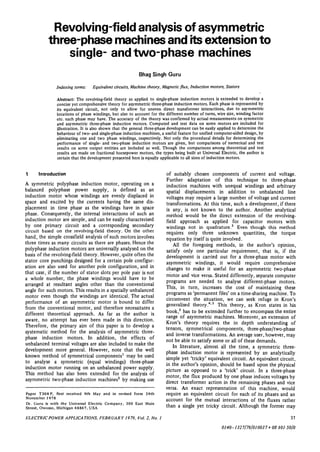
  • 3. the arbitrary displacement of the 2nd- and 3rd-phases by 62 ductors for d- and q-axs components of the said phase and d3 electrical degrees in space with respect to the windings to the effective number of conductors in the lst-phase, as shown in Fig. 1. A and B may be defined as lst-phase winding, respectively, are: the ratios of effective number of conductors in the 2nd- and 3rd-phase to the effective number of conductors in the d-axis component of 2nd-phase: Ad = Acosd2 (1) lst-phase, respectively. If kwl and Nlt Kw2 and N2, and q-axis component of 2nd-phase: Aq = A sin 62 (2) kw3 and N3 are the winding factors and the number of turns for 1st- 2nd- and 3rd-phase, respectively, then A = d-axis component of 3rd -phase: Bd = B cos 0 3 (3) (kw2N2)l(kwlNx) and B = (kw3N3)/(KwlN1). It is how- ever, obvious that for a symmetric motor, kwx = kw2 = kw3, g-axis component of 3rd phase: BQ = B sin 0 3 (4) yV, =N2 = N3, d2 = 120° and 0 3 = 2 4 0 ° . In other words, For an unbalanced three-phase power supply, the magni- A=B=l. tude of the voltage may be different for each of the phases. To simplify the theoretical development to some extent Furthermore, each phase may not be 120° apart in time. but still maintain the generality of the problem, let us Assuming the lst-phase voltage as a reference, the 2nd- and consider that the axis of the lst-phase winding coincides 3rd-phase voltages may then be given as: with the d-axis. This, therefore, is the reference-phase winding. The 2nd- and 3rd-phase windings can now be 2nd-phase voltage: V2 = C2Vt exp(jt2) (5) decomposed into their d- and q-axis components as 3rd-phase voltage: V3 = C 3 K j e x p ( / f 3 ) (6) shown in Fig. 2. The ratios of effective number of con- where C2, C3 are the constants of proportionality, and t2 and t3 are the phase-shifts for the 2nd- and 3rd-phases, respectively, with reference to the lst-phase supply. For a balanced three-phase supply, it is obvious that C2 = C3 — 1, t2 — 120° and t3 = 240° in time. The asymmetric three- phase induction motor of Fig. 2 can now be represented by an equivalent circuit. Such a circuit is shown in Fig. 3. The equivalent circuit parameters for the 2nd- and 3rd-phase, respectively, are defined in terms of the lst-phase para- meters and the effective winding ratios. The resistances /y el , rfe2 and Ayc3, as shown in Fig. 3, are introduced to account for the core loss in each of the three phases. This network representation involves six unknowns. However, by the straightforward application of The"venin's theorem, 8 the equivalent circuit of Fig. 3 may be transformed into another modified equivalent circuit as shown in Fig. 4. Fig. 1 Asymmetric three-phase induction motor with 2nd- and Srd-phase windings displaced at d2 and d3 electrical degrees from Note the terms rm,, rm2 and rm3, and Vml, Vm2 and Vm3. the lst-phase winding These are the modified resistances and the voltages for the 3-phase windings and are given as: d -axis r mi — rpirfei/(rpi (7) v mi = (8) where the subscript / = 1, 2, or 3 corresponds to 1st- 2nd- or 3rd-phase values of both the resistances and supply voltages, respectively. rpl, rp2, and rp3 are the winding resistances for 1st- 2nd- and 3rd-phase, respectively. As explained earlier, and is now obvious from Fig. 2, in all there are three windings arranged along the d-axis and two windings arranged along the q-axis. Since the currents, as shown in Fig. 4, in all the windings oriented either along the d-axis or the q-axis flow in a sense in the same direction, the mutual interactions among them are considered to be positive. Since the d- and 4-axes are in quadrature, the net flux produced by the windings oriented along one axis, say the d-axis, does not show any direct transformer linkage with the flux produced by the windings concentric with the other axis, ^-axis, and vice versa. q -axis Thus, the voltage induced in the lst-phase winding by its own leakage flux and also by direct transformer coupling of the leakage fluxes of the d-axis components of the 2nd- and 3rd-phase windings is Fig. 2 Equivalent representation of an asymmetric three-phase induction motor of Fig. 1 +AdJ2+BdI3)xl (9) The 2nd- and 3rd-phase windings are shown decomposed into d- and Similarly, the voltages induced in the d-axis components of (/-axis components the 2nd- and 3rd-phase windings by the leakage fluxes are ELECTRIC POWER APPLICATIONS, FEBRUARY 1979, Vol. 2, No. 1 39
  • 4. = /(A + AdI2 + BdI3)Adxx (10) forward: Ef2d = (h + AdI2 + BdI3)AdZf (16) = /(A + A dI2 + BdI3)Bdxx 00 backward: Eb2d = (/, + AdI2 + BdI3)AdZb (17) In a similar manner, the voltages induced in the g-axis (b) For the <i-axis component of the 3rd-phase: components of the 2nd- and 3rd-phase windings by their leakage fluxes are forward: End = (/, + AdI2 + BdI3)BdZf (18) £», = j(AqI2+BqI3)AqXl (12) backward: Eb3d = (/ t + AdI2 + BdI3)BdZb (19) #3<, = j(AqI2+BqI3)BqXl (13) Similarly, the voltages induced in the g-axis components of the 2nd- and 3rd-phase windings by the forward- and Voltages induced in the lst-phase by its forward and backward-revolving fields set by them, respectively, are: backward revolving fields as well as by direct transformer (a) For the q-axis component of the 2nd-phase: linkage of the two revolving fields set by the d-axis com- ponents of the 2nd- and 3rd-phase windings are forward: Ef2q = (AqI2 + BqI3)AQZf (20) forward: Efld = (/, +AdI2 + BdI3)Zf (14) backward: Eb2q = (AqI2 + BqI3)AqZb (21) backward: Ebld = (/, + AdI2 + BdI3)Zb (15) (b) For the g-axis component of the 3rd-phase: Likewise, the voltages induced in the d-axis components of forward: Ef3q = (AqI2 + BqI3)BqZf (22) the 2nd- and 3rd-phase windings by the field components, backward: Eb3q = (Aqf2 + BqI3)BqZb (23) which are set by them as well as by direct transformer action of the revolving fields set by the lst-phase winding, We are now in a position to express mathematically the are: speed voltages induced in the d-axis components of the (a) For the d-axis component of the 2nd-phase: windings by the forward- and backward-revolving fields of "fid a. o a 'm2 r m3 -3d -f3d -b3d 10 Fig. 3 Equivalent circuit of an asymmetric three-phase induction Fig. 4 Thevenin 's equivalent of Fig. 3 motor based upon revolving field theory 40 ELECTRIC POWER APPLICATIONS, FEBRUAR Y 1979, Vol. 2, No. 1
  • 5. the g-axis components of the said windings and vice versa. Zl3 = BdZs ~JBQZd After some simplifications, the expressions for these voltages are: Z23 = sabzs + JCabZd Z31 — BdZs + /BqZd (40c) A', = -j(AqI2+BqI3)Zf (24) (25) Z32 = SabZ s-jcabzd E* = }(Aqf2+BqI3)Zb z33 — r m3 -B2Zs E3 = ~KAqI2 + BqI3)AdZ, (26) with lU = j(AqI2 + BqI3)AdZb (27) zd zb zs — Zf ' Zb T jx 1 (41) Es = -j(Aqf2 + Bqh)BdZf (28) Sab = AdBc + AqBq Cab = AqBd-AdB (29) Once again, eqn. 40a gives the Z-coefficients for single £"7 = / ( / , + AdI2 + Bdf3)AqZf (30) phase motors, whereas eqns. 40a and 40b are for two-phase motors. Needless to say, all the above equations for the ^s = " / ( A + ^ d / 2 + BdI3)AqZb (31) Z-parameters are needed for symmetric or asymmetric £9 = /(/i + i4 d / 2 + Bdh)BqZf (32) three-phase induction machines. Eqns. 37—39 may be rewritten in a concise matrix form as ff,o = ~J(h + Adh + Bdh)BqZb (33) [Z] M = [V] (42) Simultaneous equations for the voltages in the three circuits where [Z] is a complex impedance matrix of dimensions of Fig. 4 can now be written by summing up the voltages in 3 x 3 whose elements are given in eqn. 40 in terms of each of the three stator windings, obtaining known motor-circuit constants. [/] and [V] are the column vectors for the circuit currents and the Thdvenin 1/ — f. r + / • ' . . -I- F , • + F.. . 4- F 4- P- f^& equivalent of the impressed voltages, respectively. The 'ml •'I'ml ' Lj d ' '-'fid ' ^bld ' lj 1 -'2 Wv circuit currents can then be determined from the following equation: r + Vm2 ~ h m2 ^2d + Ef2d + ^b2d + E3 + E4 2q [/] = [ Z p t K ] (43) E-,n + Ef2q + Eb2q + En + E8 (35) i + ^63d + Es + E6 where [Z]"1 dentoes the inverse of the [Z] matrix. +E9+ E10 (36) The actual phase currents can now be determined from l3q the following relation:8 Eqn. 34 is for the referenced-phase winding and can be used Ipi = (Vt + Iirfei)l(rpi + rfei) (44) to analyse a single-phase induction motor running on the for / = 1,2, and 3, respectively. main winding only, by equating the 2nd- and 3rd-phase The total power input in phase / is given by currents involved implicitly to zero. Adding eqn. 35, we can obtain the performance of two-phase symmetric/asymmetric (45) motors with balanced/unbalanced terminal voltages at any The forward and backward torques can be calculated speed of rotation. Remember that a permanent-split capaci- independently for each one of the three phases. This can be tor motor is only a special case of an unbalanced two- done by calculating the forward and backward voltages phase induction motor. Further, these equations can also be induced in each of the windings from eqns. 14—33, and used to determine the locked-rotor torque and the starting multiplying each voltage by the conjugate of the actual performance of a single-phase induction motor whose current flowing in the winding of concern and using only auxiliary-phase is disconnected at a predetermined speed. It the real part of the product. Following this procedure, and is, however, obvious that all the above equations are needed after some simplifications, the torques developed in to predict the performance of an asymmetric or a sym- synchronous watts for each of the three phases are: metric three-phase induction motor. (a) For the lst-phase: By making direct substitutions for the induced voltages, eqns. 9—33, and after some rearranging, eqns. 34—36 can by forward field: 7>, = Re [IfI?2f] (46) be rewritten in the general form as by backward field: Tbl = Re [IbI*Zb] (47) V = IZx +I2Z12 + I3Z3 (37) (b) For the 2nd-phase: = V 2 hZ2 +/)Z 2 2 +/3Z23 (38) by forward field: 7>2 = Re{/fI2*Zf (Ad +fAq)} (48) 32 Z33 (39) by backward field: Tb2 = Re {IbI2*Zb (Ad-jAq)} (49) where the Z-coefficients are (c) For the 3rd-phase: = r +Zs (40a) by forward field: 7} 3 = Kt{IfI*Zf (Bd + jBq)} (50) Zn - A dZ s -jAqZd by backward field: Tb3 = Re{IbI3*Zb(Bd-jBq)} (51) Z2x = AdZs+jAqZd (40b) where the symbol * indicates the conjugate of the com- Z72 = rm2 +A2ZS plex quantity involved and ELECTRIC POWER APPLICATIONS, FEBRUARY 1979, Vol. 2, No. 1 41
  • 6. If = /, + I2 (Ad -jAq) + I3(Bd -jBq) (52) studied in the subsequent paragraphs. In the first example, a typical 230V, 60 Hz, 0-4 h.p., Ib = h+h(Ad+jAQ)+I3(Bd+jBq) (53) 4-pole symmetric three-phase induction motor rated at The overall forward and backward torques developed, in 1650r/min is considered. The windings in each phase synchronous watts, including friction and windage losses consisted of two concentric coils, the inner coil was wound are: n over 6 teeth and had 57 turns, the outer coil was wound over 8 teeth with 76 turns of 24 gauge wire. The per phase gross forward torque developed = 7} = £ 7},- (54) 1= 1 values of the motor constants obtained from design con- n siderations are reproduced below. gross backward torque developed = Tb = £ r w (55) 1=1 r, + / x , = 12-401 +/5-77412 where « specifies the number of phases. For a three-phase motor, n = 3. rfe = 822-8 £2 The actual torque developed by the motor, in synchron- r2 +jx2 = 5-319+/2-653 ft ous watts, is xm = 88-601 ft T = Tf-Th (56) F&W = 8-70W The secondary or the gross output power can be calculated by multiplying eqn. 56 by the per unit speed of the motor. The laboratory measurements were taken by connecting the Subtract the friction and windage losses to obtain the motor to a balanced three-phase supply. The test data and useful power output. theoretical predictions on various output quantities are given in columns 1 and 2, Table 1. Note that these theoreti- 6 Procedural details cal results in this case can also be obtained by making use 6.1 Three-phase motors of well known equations for symmetric three-phase induction motors based on a single equivalent circuit. It is, The suggested procedure to predict the performance of however, necessary to increase the values of the motor three-phase induction motors is as follows: constants given above by 50%, except for the stator- (a) From the known number of turns and the winding winding resistances. factor for each of the three phases, determine A and B. A provision was made to add extra windings in series (b) From the known locations of the 2nd- and 3rd-phase with each phase of the above motor to test the motor with windings with respect to the lst-phase winding, calculate stator windings having an unequal number of turns. The the d- and 4-axis components of these windings, using eqns. tested and computed results, as given in columns 3 and 4 of 1—4. However, for a symmetric motor, set 62 = 120° and Table 1, are for a motor with 69 and 92, 66 and 88, and 57 0 3 =240°. and 76 turns in the inner and the outer coils, for the lst- (c) Assuming the lst-phase voltage as a reference, define 2nd- and 3rd- phase windings, respectively. the 2nd- and 3rd-phase voltages in terms of their magni- The last example involves a three-phase induction motor tudes and time-phase displacements. In other words, define with unequal turns in each phase and with arbitrary spacing C2 and C 3 , t2 and t3, respectively. For a balanced three- of the phases. The number of turns and coils were same as phase supply, C2 = C3 = 1, and t2 = 120° and t3 = 240°. in the previous example, whereas the 2nd- and 3rd- phase (d) Calculate Thdvenin's equivalent of resistances and were displaced at 100 and 200 electrical degress, respect- voltages by making use of eqns. 7 and 8, respectively. ively, from the lst-phase. The measured values and theor- (e) From the known constants of the motor, compute etical predictions are given in columns 5 and 6, Table 1. the Z-parameters as given in eqns. 40a, 40b and 40c. In all the foregoing cases, as is obvious from Table 1, test (/) Use a computer subroutine to invert the complex data are in close agreement with theoretical predictions. impedance [Z] matrix.' This, therefore, confirms the accuracy of the present (g) By making use of eqn. 43, calculate the complex method as applied to both symmetric and asymmetric values of the circuit currents for the modified equivalent three-phase induction machines. circuit of Fig. 4. From eqn. 53, it can readily be shown that for a sym- (h) The actual phase currents can now be determined metric three-phase supply, the backward field current Ib is using the relation given in eqn. 44. identically zero. Consequently, there exists no backward- (/) Calculate the input power and the gross torques revolving field in the motor, as expected at the outset. developed by the forward and backward fields from eqns. 45—55. The actual torque developed can now be computed 6.2 Two-phase motors (permanent-split capacitor motors) from eqn. 56. In the true sense, there are not that many two-phase (/) Determine the forward and backward I2R losses due induction motors being built toda>. The reason, of course, to the forward and backward fields by multiplying the is that the two-phase power source needed for the normal forward and backward torques developed by s and 2s, operation of such motors is virtually an extinct species. respectively. However, a permanent-split capacitor motor may be treated (k) Obtain net power developed, total losses, horsepower as a two-phase motor with unequal windings. The pro- etc. by employing standard relations. cedure outlined below may be used to determine its Since it is not possible to cite all practical possibilities, performance. theoretical and test data on three different motors are (i) Calculate A from the known turns and winding factor for each of the two windings. Set B equal to zero. t A subroutine to solve this matrix is available from the author on (ii) Use eqns. 1 and 2 to determine the d- and q- request 42 ELECTRICPOWER APPLICATIONS, FEBRUARY 1979, Vol. 2, No. 1
  • 7. Table 1: Theoretical and test results on three-phase, permanent-split capacitor, and single-phase induction motors Three-phase motors Two-phase motors (p.s.c.) Single-phase motor Column 1 2 3 4 5 6 7 8 9 10 11 12 Test Theory Test Theory Test Theory Test Theory Test Theory Test Theory /p..A 1-45 1-476 0-93 0-902 3-21 3221 0-73 0-734 0-76 0-761 0-97 0-960 / P J ,A 1-47 1-476 0-67 0-678 1-12 1053 0-38 0-383 0-26 0-258 — - 'P3.A 1-45 1-476 2-10 2085 3 54 3-658 — — — — — — Pint.™ 150 0 156-3 83-7 80-44 172-5 177-5 160-7 160-7 151-7 153-1 181-2 179-7 Pirn.™ 1520 156-3 80-3 77-24 84-7 82-85 820 81-57 60-3 59-33 - - Pim.W 1515 156-3 240-2 243-1 380-1 384-1 _ — — — — — Pout. W 298-9 3063 255-5 252-5 237-9 235-5 158-6 157-8 139-1 173-7 114-7 112-4 T, kgm 0-1764 0-1808 0-1508 0-149 0-1404 0139 00936 0 0931 00821 00812 0-967S) 00664 Efficiency 0-66 0-65 0-63 0-63 0-37 0-37 0-65 0-65 0-66 0-65 0-63 0-63 components of the 2nd-phase (auxiliary phase for a perma- 6.3 Single-phase motors nent-split capacitor motor). The starting performance of single-phase motors can be (iii) Define the magnitude and the phase angle for the obtained by using the method explained in Section 6.2, 2nd-phase voltage reference to 1st-phase voltage. In other since starting the motor employs both the windings. How- words, define C2 and t2. For a two-phase motor with ever, when the motor is running at its rated speed on the balanced two-phase terminal voltages, C2 = 1 and t2 = 90° main winding only, its performance can be obtained by (time). However, for a permanent-split capacitor motor modifying the procedure of the previous subsection as (p.s.c.), set C2 = 1 and t2 = 0°. follows: (iv) Calculate from eqns. 7 and 8, the The'venin's equiv- (a) Determine The'venin's equivalent of resistance and alent of resistances and voltages. Note that for a p.s.c, the the voltage from eqns. 7 and 8, respectively, for the main capacitor impedance should be added to the auxiliary- winding. winding's resistance for all theoretical purposes except for (b) Set I2 = h = 0 and A = B = 0. obtaining the primary loss for that winding. (c) Compute Zn from eqn. 40a. (v) Compute the Z-parameters from eqns. 40a and 40b. (d) Calculate the current I as follows: Note that eqn. 40c is not needed in this case because there are only two-phase windings. Therefore, set/ 3 = 0. A = Vml/Zn (vi) Steps (vi)-(xi) are essentially the same as those given in Section 6.2. Compute the power input, the forward and Other quantities of interest can be obtained by following a the backward torques with n = 1. similar procedure given in the previous subsections, of Two permanent-split capacitor motors were actually built course, overlooking nonessential equations. to verify the accuracy of the present method as extended to One of the p.s.c. motors was selected for the testing two-phase induction motors. One motor was built with an purposes as a single-phase induction motor. At its rated auxiliary winding displaced in quadrature with respect to speed, 1650r/min, the auxiliary winding was cut off. The the main winding, while the other with auxiliary arranged test data and the theoretical predictions on various output at 60 electrical degrees from the main. Since the same quantities are given in the last two columns of Table 1. The windings were used for both motors, the following motor feasibility of using the present development to analyse constants are applicable to either of them: single-phase induction motors running on the main winding only is indicated by the close relationship between the rpx + jxx = 32-255+/ 35-49 ft measured and theoretically predicted values. Therefore, it can be concluded that a single-analysis rn = 6884-05 ft computer program based on the equations presented in this paper may be used effectively to analyse single two- and r 2 + / x 2 = 36-453+/21-238 ft three-phase induction motors. In addition, the phase xm = 735-544 ft windings may be either equal or unequal, and the spacing among the phases may be arbitrary. A = 1-32107 7 Conclusions rp2 = 135-194ft This paper provides, first, a basic theory to predict the capacitance = 3 05 mF behaviour of an asymmetric three-phase induction motor using revolving-field theory, secondly, extensions of the These 230 V, 60 Hz, 4-pole permanent-split capacitor above for single- and two-phase induction motors, and motors were tested at 1650r/min. The tested and com- thirdly, detailed step-by-step analysis procedures for such puted results on quadrature and nonquadrature motors are motors. A computer program was developed based upon given in Table 1, columns 7 and 8, and 9 and 10, respect- the present development and is being used extensively by ively. It is obvious from these results that the correlation the Application Department to analyse such induction between the tested and computed values is excellent and machines as split-phase, permanent-split capacitor with thereby approves the applicability of the general method to either quadrature or nonquadrature windings and sym- permanent-split capacitor motors, and in turn to other such metric or asymmetric three-phase motors. To demonstrate motors that use two windings for their operation at the the effectiveness of the present theoretical approach, rated speed. however, actual measurements and theoretical predictions ELECTRIC POWER APPLICATIONS, FEBRUARY 1979, Vol. 2, No. 1 43
  • 8. on various output quantities are reported. In each case 9 References given in this paper, and almost all others not included here, 1 FORTESCUE, C. L.: 'Method of symmetrical coordinates a remarkable correlation exists between theory and actual applied to the solution of polyphase networks', Trans. Amer. tests. Needless to say there is a reduction in the cost of Inst. Electr. Engrs., 1918, 37, pp. 1027-1115 maintaining a single permanent file on a time-sharing 2 LYON, W. V., and KINGSLEY, C. Jun.: 'Analysis of unsym- system instead of three separate files that otherwise would metrical machines', ibid., 1936, 55, pp. 471-476 be needed to predict the behaviour of single- two- and 3 PUCHSTEIN, A. F., and LLOYD, T. C: 'Capacitor motors with windings not in quadrature', ibid., 1935, 54, pp. 1235-1239 three-phase induction machines. 4 ALGER, P. L.: 'The nature of induction machines' (Gordon and Breach, 1965), chapters 5 and 11 5 KRON, G.: 'Equivalent circuits of electrical machinery' (Wiley, 8 Acknowledgments New York, 1951) 6 GURU, B. S.: 'Revolving-field analysis of capacitor motors with The author would like to thank J. Postema for his comments nonquadrature windings', Electr. Mach. & Electromech., (to be on the manuscript and for several useful discussions during published) the development of this paper. The author is grateful to H. 7 VEINOTT, C. G.: 'Theory and design of small induction motors', (McGraw-Hill, New York, 1959), Chap. 9, pp. 167-175 Penhorwood, Director Engineering Division, for granting 8 GURU, B. S.: 'Two-equation analysis of a capacitor motor by permission to publish this paper. The author also owes his cross-field theory', Electr. Mach. & Electromech., 1978, 2, pp. appreciation to C. Yeiter for expertly typing the manu- 147-153 script and to D. Austin in drafting the Figures for this 9 TRICKEY, P. H.: 'Iron loss calculations on fractional horse- paper. power induction motors', Trans. Amer. Inst. Electr. Engrs., 1959,pp. 1663-1669 44 ELECTRIC POWER APPLICATIONS, FEBRUARY 1979, Vol. 2, No. 1