Provides online help information.
Call: Enables bidirectional listening function. The PC speaker and microphone
can be used to realize bidirectional communication between the IP camera
and PC.
Speaker: Enables one-way listening function. The PC can listen to sounds
captured by the IP camera microphone.
3.1.4 Image Adjustment
Click the image to enter the image adjustment interface. Adjust brightness, contrast,
saturation and other parameters to obtain optimal image effect. The adjustment takes
effect in real time.
3.1.5 Full Screen Display
Click to switch the display to full screen. Right click or press Esc to exit full screen.
3.1.
Brickcom vd300-af Info Tech Middle East - Best Buy
Gd28 Xx User Manual
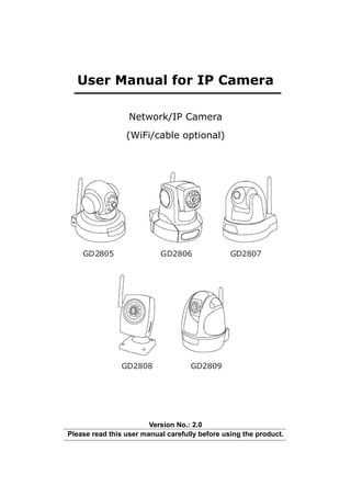
1. User Manual for IP Camera
Network/IP Camera
(WiFi/cable optional)
Version No.: 2.0
Please read this user manual carefully before using the product.
2. Contents
Overview…………………………………………………………………………1
Brief Introduction………………………………………………………………………..1
Features………………………………………………………………………………….1
Operating Environment……..…………………………………………………...........2
Technical Specifications………………………………………………………….........3
Structure and Installation……………………………………………………….3
Software Settings……………………………………………………………3
Liview………………..………………………………………………………………….4
System……………………………………………………………………….9
Video………………………………………………………………………..10
Audio………………………………………………………………………...11
Motion……………………………………………………………………….12
Network…………………………………………………………………......13
Advanced……………………………………………………………………15
User Manage……………………….……………………………………….17
Image Set…………………………………………………………………...18
SD Card………………………………….……………………………….....18
Appendix……………………………………………………………………..18
Network Ports Occupied by IP Camera………………………………………..18
Default Network Parameters……………………………………………………..19
Application and Setting of DDNS Domain Name……..……………………………19
WiFi Setting and Connection……………………………………………………23
Access and Setting of IP Camera in Different Network Environments…………..27
Port Mapping in Router……….……………………………………………………….32
FAQs………………………………………………………………………………...35
Ordering Information…………….………………………………………………..39
3. 1. Overview
1.1 Brief Introduction
The product is a digital IP camera. With a high-integration SOC chip, it integrates video
acquisition, compression and network transmission into a single device and provides a
high-definition, high-integration and low-cost solution for LAN-/WAN-based remote video
surveillance of users. The IP Camera is applicable to medium/small homes or business
offices and various occasions needing remote network video transmission and monitoring.
The product features easy installation and convenient operation.
1.2 General Features
H.264 Integrated intelligent IP camera with high-performance programmable media
processor
Optimized H.264 video compression, easy transmission of high-definition images at
low network bandwidth
Max. 10 users simultaneous browsing online
Embedded Web Server to facilitate real-time monitoring and setting management via
IE window
Support Wi-Fi/802.11b/g wireless network(* wifi module for optional)
Real-time browse/recording/snap/retrieval/replay/download
Dynamic Domain Name Server (DDNS), supporting LAN and Internet
Diversified network protocols: HTTP, TCP, IP, UDP, SMTP, DDNS, DNS, SNT, DHCP,
FTP, and so on
Network adaptation technology: automatic adjustment of video frame rate based on
network width
Motion detection alarm (settable area and sensitivity), alarm recording, and alarm
mail sending
Support Imaging area masking
Automatic fault recovery: automatic connection after network interruption
Remote system upgrade
Special Features for each model
GD2805 GD2806 GD2807 GD2808 GD2809
Pan /Tilt (270/120deg.) √ √ √ √
SD card √ √ √ √ √
Wireless Wi-Fi √ √ √ √ √
IR night vision (5m) √ √ √ √
Bi-directional listening √ √ √ √ √
Built-in microphone √ √ √ √
External alarm input/output √ √
Waterproof function √
-1-
4. 1.3 Operating Environment
Minimum Hardware Configuration:
CPU: Pentium 2.0 GHz
Memory: 256 MB
Graphics card: TNT2
Audio card: Mandatory for listening and bidirectional intercom
Hard disk: Not less than 40G for recording images
Recommended Hardware Configuration:
CPU: Pentium 2.6 GMHz
Memory: 512 MB
Graphics card: Nvidia Geforce FX5200 or ATI RADEON 7000(9000) 128M video
memory
Operating System:
32-bit Windows2000, Windows XP, Windows2003 and Windows Vista of Simplified
Chinese/English Edition, and 64-bit Windows2003, Windows XP and Windows Vista
of Simplified Chinese/English Edition)
Software:
Internet protocol IPv4 (Note: IPv6 not supported for the time being)
IE 5.0 or above
DirectX8.0 or above
TCP/IP
Other demands:
The graphics card of the PC running this software needs to support color conversion
and zoom of images. Presently graphics cards tested included Nvidia Tnt/Tnt2,
Geforce Mx200/400/420/440 Fx5200/5600, ATI Radeon
7000/7200/7500/85009000/9200/9500/9600, MatroxG450/550, and INTEL845G/865G.
Note that the driver for the graphics card must support hardware zoom.
-2-
5. 1.4 Technical Specifications
Item Parameter
Image sensor 1/4’’CMOS, 300,000 pixels, minimum illumination: 1
Lux
Video compression algorithm H.264 baseline profile @Level 2.2
Video resolution VGA: 640*480, QVGA: 320*240
Night vision distance 5m(only for GD2805/GD2806/GD2808/GD2809)
PTZ control angle Horizontal: 270°; vertical: 120°
Video adjustment parameters Brightness, contrast, image quality
Stream format Pure video stream or composite audio/video stream
Video frame rate 1~30 frame/second
Video compression bit rate 16Kbit/second ~ 4Mbit/second
Audio input One linear input or embedded passive MIC input, MIC
impedance: 1000KΩ
Audio output One linear output
Audio compression algorithm G.726
System interface RJ-45, 10/100M Ethernet interface
SD card slot; Maximum: 32GB (SD2.0 protocol)
Wi-Fi module IEEE802.11b/g wireless network
Input power supply GD2805/2806/2807/2809: 9V/1.5A; GD2808:5V/2A
Maximum power 6W
Operating temperature 0~+40°C
Operating humidity 10~85%
Dimensions (D x W x H) GD2805: 104 x 125 x 106 (mm)
GD2806: 103 x 104 x 103 (mm)
GD2807: 116 x 140 x 129 (mm)
GD2808: 78 x 68 x 128 (mm)
GD2809: 109 X 112 X 134 (mm)
Weight (approx.) GD2805: 260g, GD2806: 298g , GD2807: 345g
GD2808: 402g, GD2809: 440g
2. Structure and Installation
Please refer to the Quick Installation Guide in the packaging box.
3. Software Settings
Enter the IP address of the IP camera in the IE address bar, for example, the default
address of http://192.168.1.1. Enter the user name and password (both “admin” by
default) to log on.
-3-
6. 3.1 Liview
3.1.1 Setting Items
On the left of the Homepage are items that a user can visit or set. If an item is
clicked, the corresponding item turns yellow, and meanwhile goes to its setting
interface. For detailed settings, refer to the following descriptions.
Note: Only the system administrator has the right to set parameters.
3.1.2 PTZ Control and Alarm Messages
-4-
7. Meaning of icons:
1. Up 2. Down 3. Left 4. Right
Note: All above actions involve inching control.
5. Click to return to the default initial position
6. Click to rotate once in horizontal direction
7. Click to rotate once in vertical direction
8. Click to stop continuous rotation
9. Alarm message column: displays alarm time and type in case of any alarm
3.1.3 Functional Buttons
If clicked for the first time, the above icons will turn green (except Alarm),
indicating the function is enabled. Clicking again recovers the initial status and
cancels the function.
Meaning of functional buttons:
Snap: Snaps a JPEG picture and stores it in the designated path, as shown
in the following figure:
Record: Records video files and stores them in a designated path. If the
listening function (Call or Speaker) is enabled, recording can be made at the
same time.
During recording, to visit a setting item, an alert message appears,
prompting that “This will be stopped if you turn to the other pages,
continue?”, as shown in the following figure:
Call: Enables the intercom function. Please connect the Audio signal line
of the device to the related audio device.
Speak: Enables the listening function. The device has a built-in MIC to listen
on-site voices in real time.
Alarm: If the motion detection alarm function is set, (refer to the section of
Motion for details), the indicator turns red and blinks after an alarm is
triggered.
-5-
8. After an alarm is triggered, double click on this icon stops alarm and
meanwhile clears the content in the alarm message column.
By default, an alarm event will stop automatically in ten seconds after
being triggered.
Replay: Enables online playback of record files, as shown in the following
figure:
3.1.4 Retrieving Record Files
The user can search record files in the local PC or SD card (DEV) of a device.
Date: Select a query date and click . The calendar selection interface appears,
as shown in the following figure:
<<Decrease year
>> Increase year
<Decrease month
> Increase month
After a date is selected, the calendar interface closes automatically.
PC: Queries record files in the local PC.
-6-
9. DEV: Queries record files in the SD card.
Click to search record files in the PC or SD card on the designated date.
The method for querying record files in different durations of a day is as shown in
the following figure:
The Record part displays the list of record files queried.
The Pic part displays the list of record files queried.
The left of each part displays hour(s), one hour for each bar;
The right of each part displays minute(s), 2 minutes for each bar;
Displays a currently selected time;
Displays the currently queried record files or picture files in a
time segment;
File List
Displays a list of the currently queried record files or JPEG
pictures.
3.1.5 Playing Record Files
Select a record file or JPEG file to be played from the File List or double click
to play. During play, the right window clock displays the played content so that
the user can view playing information and operate played content, as shown in the
following figure:
Progress
Respectively indicates: Open a file, play, pause, stop, fast backward, fast forward,
single frame forward, volume switch, cyclic play, snap
Note: After a motion detection alarm recording is triggered (refer to Motions
Settings for details), if the user selects to store record files in the SD card
and meanwhile enables audio recording, mosaic may occur to pictures upon
replay. Therefore, audio recording is not recommended when recording in
the SD card is made.
-7-
10. 3.1.6 Download of Record Files in SD Card
Select a record file in the SD card from the File List. Click to download the file
to the local PC.
Click . The Download Information window appears. The user can view the file
download information, as shown in the following figure:
During download, if the <Pause> button is clicked, the download pauses. Clicking
<Start> resumes the download of the uncompleted file. After download, you may
click the <Delete> button to delete downloaded files.
Click the <Close> button to exit the Download Information window.
3.1.7 OSD Display
The current date and time are displayed on the upper part of the interface.
The IP camera name and the number of users currently visiting the IP camera are
displayed on the lower part of the interface.
-8-
11. 3.2 System
Time Sync: The system clock of the IP camera synchronizes with the PC.
NTP Parameters: The system clock of the IP camera synchronizes with the clock of
the NTP Server.
This function is enabled by default. Please select and save a time zone and
switch to the Live View interface. The upper part of the interface will display
the calendar and clock of the NTP Server.
System Information: Displays device name and device ID.
The device name may be a user-defined one and the ID is the unique identity
upon device delivery.
Note: The device name shall be saved after modification, and the IP camera will
reboot automatically.
Upgrade: software upgrade
Three files needs upgrade, that is, uke file, uoc file and uot file, as shown in the
following figure:
Click the <Browse…>button to select an upgrade file.
Click the <Upgrade> button to confirm and download the file to the system. During
-9-
12. this process, the system will display an upgrade progress bar. After the upgrade is
completed, the system prompts “upgrade succeeded”, and meanwhile, the IP
camera reboots automatically (it takes about 5 seconds). Please wait.
Version: version number of the current software, such as 6.0.2.2.
Note: During upgrade, make sure that the power supply and network connection of
the IP camera shall not be interrupted.
For obtaining of upgrade files, please contact our company or the local dealer.
Our company shall not be held liable for any device failure arising from
unauthorized upgrade files.
Storage Parameter
Storage path for record files, the default path is: C:XDNVS.
System Operation
Restore Default: Restores the default settings. Please use this function with
care.
Reboot: Automatic device reboot; the IP camera will reboot in about five
seconds, please wait.
3.3 Video
I
Image: Image resolution setting
- 10 -
13. VGA: 640*480; QVGA: 320*240; save any resolution modification, and the
device will reboot automatically.
Quality: Image quality setting
The user may select Fine, Normal and Basic according to the actual needs.
Fine is selected by default.
Note: Different image resolutions and qualities occupy different network
bandwidth. Please make settings with reference to the table of IPCAMERA
Bandwidth Application and Parameter Setting.
Environment Power Frequency: Selection of operating environment and power
frequency of light
According to different lighting environments, select the power frequency of
50Hz or 60Hz. 60Hz is selected by default.
Note: Wring power frequency selection may cause image flickering.
In case of poor illumination of device installation site or night use, select the
night vision mode IR Night.
Video Mirror and Video Flip :
Image mirror and flip: if hanging installation is taken for the device, images may
be inversed, so these two functions can be enabled for adjustment.
Video mask set: mask of private images
To protect some monitored areas from other persons, images of such an area
can be masked.
An entire image is split into 22*18 small areas. Double click or drag your mouse
to select one or more areas to be masked.
All: Sets to mask the entire image.
Clr: Clears the masked area(s).
3.4 Audio
Input type: Selection of external audio input type
Mic (microphone) input or Line In (linear) input.
Type: Displays audio code format
Bit rate: Displays audio bit rate.
- 11 -
14. 3.5 Motion
Schedule: Sets the arming duration for motion detection.
Enable Detect: Enables or disables motion detection.
Sensitivity: Motion sensitivity setting, ranging from 1 to 100 (80 by default); 1
means the lowest sensitivity while 100 means the highest sensitivity
Alarm Record in PC: Enables local PC recording after alarm trigger.
Alarm Record in SD card: Enables SD card recording after alarm trigger.
Alarm Snap in SD card: Snap site images in JPEG format and store them in the SD
card after alarm trigger. If alarm trigger continues, an image
will be snapped and stored in the SD card for about every
ten seconds
Area set: Click and drag your mouse to determine a detection area.
All: Sets the entire video as the motion detection area.
Clr: Clears all motion detection areas.
- 12 -
15. 3.6 Network
Basic Parameters: setting of basic network parameters
If fixed IP (such as static extranet IP or LAN) is used for IP camera connection,
it is necessary to make setting here.
IP address: Fills in the IP address of the IP camera.
Subnet mask: Fill in the subnet mask, such as 255.255.255.0.
GateWay: Fill in the gateway address.
MAC: Physical address of the IP camera, its unique identity over the network.
Do not change its settings at will.
Data port No: Data stream transmission port
HTTP port No: Web access port
DNS address: Fill in the local DNS address.
For detailed parameter settings, consult your network administrator or the local
ISP (Internet Service Provider).
For LAN application, please avoid conflict between the IP address of the IP
camera and that of the internal PC over the LAN.
Enable DHCP: Enables DHCP service or not.
If a DHCP Server exists over your network (for example, the LAN has a router
device providing DHCP service), after this function is enabled, the DHCP
Server will automatically allocate an IP address to your IP camera.
WiFi Parameters: Settings of wireless WiFi parameters.
- 13 -
16. A WiFi module can be configured for the device to support wireless network
connection. It is applicable to a network environment with wireless AP devices
(such as wireless router).
Enable WiFi: Enables or disables WiFi function.
IP address: Sets a wireless IP address which shall not be in the same
network section as the wired network address (i.e., IP address in
Basic Parameters.
Subnet mask: Sets subnet mask of the wireless network.
Gateway: Gateway address of the wireless network. It shall not be in the
same network section as the wireless gateway address (the
Gateway address in Basic Parameters).
SSID: A login name for identity verification of the wireless network. On a user
passing identity verification is authorized to access the wireless
network. It shall be the same as the SSID set in the wireless network
(router/AP).
Password: Wireless network encryption password.
Frequency band: After successful connection, the frequency bandwidth of the
wireless network is displayed.
Mode: After successful connection, the connection mode of the wireless
network is displayed.
Note: The WiFi setting and connection are complicated. For detailed settings,
refer to the section of “WiFi Setting and Connection” in the appendix.
DDNS Parameters: DDNS domain setting
The setting of this item can bind the IP camera with a fixed domain name so
that it can access the network via domain name, regardless of change of the
public IP address of the camera.
DDNS provider: Select the DDNS Server. The device supports three DDNS
Server addresses:
viewipcam.com, camdns.cn, and 3322.org .
DDNS regName: User name the user registers with the DDNS Server.
DDNS password: Password the user registers with the DDNS Server.
DDNS domain: Remote access domain name set after logon to the DDNS
Server.
DDNS server URL: DDNS Server address, such as www.3322.org
DDNS server port: DDNS Server connection port, 30000 by default.
Data port map No.: If the device is mapped into a public network via a network
server (e.g., a router), fill in the data port number of the
public network used after device mapping, 5000 by
default.
HTTP port map No.: If the device is mapped into a public network via a
network server (e.g., a router), fill in the web port
number of the public network used after device
mapping, 80 by default.
- 14 -
17. Note: To implement normal DDNS domain name access, set the correct local
DNS address. For details, refer to DNS Address setting in Basic
Parameters. The default DNS address of the IP camera is a DNS address
of Guangdong province in P.R.China. To enable the DDNS function outside
Guangdong, set the correct local DNS address.
Note: For detailed application and setting of DDNS domain name, refer to
<Application and Setting of DDNS Domain Name> in the appendix.
PPPOE parameters: Setting of PPPOE dial-up Internet access parameters
The device supports PPPOE dial-up Internet access. If only the user fills in the
correct information, the device can make network access connection
independently. Since the IP address for dial-up Internet access is a dynamic
one, the user is recommended to apply for and set the DDNS domain name.
Please set the following PPPOE parameters:
Enable PPPOE: Enables or disables PPPOE function.
PPPOE URL: The current IP address displayed after successful dial-up
connection (no need to set).
PPPOE username: Fill in the user ID. Please consult your local ISP.
PPPOE password: Fill in the password. Please consult your local ISP.
Online Time: Displays the online network connection duration (no need to set).
Note: The connection of the IP camera over different networks needs different
parameter settings. For details, refer to <Access and Setting of IP
Camera in Different Network Environments> in the appendix.
After parameter setting, click <Save>. The device needs to reboot (about 5 seconds),
please wait.
3.7 Advanced
Mail Parameters
If the user has set motion detection alarm and enabled alarm mail sending
function (for details, refer to Motion setting), complete related mailbox setting
here.
SMTP server: Address of the SMTP mail server, such as the Gmail SMTP Server
- 15 -
18. is smtp.gmail.com.
MAIL from: Inbox address
MAIL to: Outbox address
SMTP username: Logon user name for the mailbox sending alarm mails
SMTP password: Logon password for the mailbox sending alarm mails
MAIL title: The title of a mail
SMTP port: Port number of the SMTP Server
SSL: Supports SSL security authentication or not
Alarm send mail: Enables alarm mail sending function
Snap picture: Enables picture snap function. Snapped pictures will be sent
as an attachment to the alarm mail. A JPEG picture will be
snapped every 10 seconds even if the alarm is continuously
triggered in 10 seconds.
Note: Normally, the default port number of an SMTP Server is 25 (such as the
163 mail server), and no SSL authentication is needed. However, some
mail servers use special SMTP port, for example, the Gmail uses the
465 port, and meanwhile, SSL authentication is needed. When
selecting a mail server, the user must clearly know the latest SMTP port
of the Server and whether it supports SSL authentication. Furthermore,
some free mails do not support SMTP service.
UPNP parameters
Automatic port mapping: this function is enabled if the LAN has a server (such
as a router) with UPNP function, so the server will automatically map the port
set for the IP camera into an external network (such as the Internet).
UPNP network card: Type of network card connecting the UPNP Server:
Lineate or WiFi.
UPNP mode: includes two modes: Designate and Auto. The Designate mode
means the data map port and Web map port are designated for
the server, while the Auto mode means the server sets the data
map port and Web map port.
UPNP server: gateway address of the network server with UPNP function.
Data port map No.: Data port number.
HTTP port map No.: Web port number.
Data mapping status and HTTP mapping status: Port number displayed after
successful mapping.
After setting, click <Save>. The settings take effect.
- 16 -
19. 3.8 User Manage
T he IP camera provides two levels of user access rights:
Administrator: system administrator with the highest right who can access the device
and modify all of its parameters.
User: Ordinary users who can log on and acce ss the device, but cannot set and
modify its parameters. If such a user access related setting items, the
system will prompt access rejection information, as shown in the follow ing
figure:
Plea se fill in and remember the following user management information:
Username: Fill in the name of the authorized user.
Password: Fill in the password of the authorized use r.
Confirm Password: Confirmation of the user’s password .
The Username and Password must be a case-sensitive string composed of one to
sixteen letters, digits, underlines or dots (.).
After setting, click <Save>. The settings take effect.
- 17 -
20. 3.9 Image Set
The user can adjust the brightness and contrast of images to suit different
operating environments. Click Image Set. The following window appears:
Brightness adjustment, 13 by default
Contrast adjustment, 23 by default
Click to decrease the magnitude by 5
Click to increase the magnitude by 5
Click to restore default settings.
The image browse interface on the right can display the brightness and contrast
adjustment effect in real time.
After setting, click Image Set. The widow closes.
3.10 SD Card
Query the information about the current SD card.
On the blank of the interface, right click. A dialog appears. Select Refresh to view
the total size and free size of the SD card. If Empty is displayed, it indicates no SD
card is inserted into the IP camera.
Note: The SD card adopts cyclic recording mode. If the system finds that the
recording space of the card is used up (the free size is less than about
60MB), it will automatically overwrite the previously recorded files.
Therefore, please properly download and back up the recorded files in the
SD card.
4. Appendix
4.1 Network Ports Occupied by IP Camera
By default, the IP camera occupies the following ports:
TCP 80 (Web port) 5000 (communication port, audio/video data
transmission port, intercom data transmission port)
UDP 5000 Audio/video data transmission port
Multicast Initial multicast port + channel ID
port
- 18 -
21. 4.2 Default Network Parameters
Wired network:
IP address: 192.168.1.1
Subnet mask: 255.255.255.0
Gateway: 192.168.55.1
Data port: 5000
Web port: 80
DHCP: disabled
Wireless network:
Wireless IP address: 192.168.55.1
Subnet mask: 255.255.255.0
Gateway: 192.168.1.1
4.3 Application and Setting of DDNS Domain Name
4.3.1 DDNS Overview
Presently the most IP addresses an ISP provides are dynamic ones (such as ADSL
dial-up Internet access). However, a fixed IP is needed for remote access of many IP
cameras. The cost for a fixed IP is unacceptable to customers. Therefore, DDNS
provides a brand-new solution which can capture the variable IP and relates it to the
domain name. In this way, a customer can access the IP camera by the domain
name.
4.3.2 Application for DDNS Domain Name
To access the IP camera via a DDNS domain name, first register a DDNS domain
name (domain) with the DDNS Server.
The device supports three DDNS Servers: 3322.org, viewipcam.com, and camdns.cn.
The user can select anyone of them. In the following we will take viewipcam.com as
an example to describe the application for DDNS domain name.
Log on to www.viewipcam.com.
- 19 -
22. Select Sign Up.
Fill in User ID and your E-mail address. Click <Next Step>.
- 20 -
23. Fill in the login password. Click <Create User ID>.
The User ID has been created successfully. The system prompts the user to check an
E-mail from the Astak DDNS Server to activate the User ID.
Check your E-mail, and click to activate your
User ID.
- 21 -
24. Fill in a DDNS domain name (such as “ip2805”) and network port (such as “80”) you want
to use. Click <Upgrade Domain Name>
The domain name has been assigned, and the system prompts the user to complete the
DDNS domain name setting in the IP camera.
- 22 -
25. 4.3.3 DDNS Setting in IP Camera
Log on to the IP camera. Enter DDNS Parameters under Network. Fill in the user
name, password and domain name registered with the domain server viewipcam.com,
as shown in the following figure:
Save the settings. The IP camera will reboot.
In this example, your IP camera has accessed to the Internet, and its domain
name is http://ip2805.viewipcam.com. Enter it in the IE address bar, and you
can access the device via the DDNS domain name.
Note: If you use the DDNS domain name to access the IP camera, do not add
“www” to the IE address bar.
4.4 WiFi Setting and Connection
If your IP camera has WiFi configuration, your IP camera can access a WiFi
network in wireless mode with a wireless AP device (e.g., a wireless router). This
section takes a Linksys wireless router WRT54GL as an example to describe WiFi
setting and connection.
- 23 -
26. 4.4.1 Wireless Router Setting
First, enable the wireless function of the router.
Log on to the wireless router setting interface. Select the Wireless item.
Select Basic Wireless Settings. Please complete the following settings:
(1) Wireless Network Mode: Mixed is recommended to enable the wireless function
ad support the 802.11b/g standard. Selecting Disable
disables the wireless function.
(2) Wireless Network Name(SSID): Fill in SSID (linksys is selected by default)
Click <Save Settings> to save the settings.
To encrypt the wireless network, select Wireless Security.
- 24 -
27. Please complete the following settings:
(1) Security Mode: Please select WEP.
(2) Default Transmit Key: Select which group of key is used.
The key may be manually set or automatically generated by clicking <Generate>.
Please select or set one among the four groups of keys.
Remember the set SSID and key, since you have to fill in the information during
WiFi setting of the IP camera.
4.4.2 WiFi Setting of IP Camera
Log on to the IP camera. Enter the Network. Fill in the IP address, Subnet mask, Gateway,
SSID, password and other items in WiFi Parameters, as shown in the following
figure:
- 25 -
28. 4.4.3 Precautions on WiFi Settings (This is very important, please read
carefully)
(1) The wireless IP address shall be in different network section from the wired IP
address. If the wireless network section is 192.168.1.XXX, the wired IP
address in Basic Parameters shall be set in another network section such as
192.168.2.XXX .
(2) Please disable DHCP function in Basic Parameters.
(3) The WiFi encryption mode only supports WEP mode for the time being. Please
select WEP in the wireless router.
(4) The SSID and encryption key shall be the same as that set in the wireless
router.
(5) In case of WiFi transmission, delay or stagnation may occur to browse of VGA
pictures due to influence of wireless transmission bandwidth of the device. It is
recommended that the image format be set to QVGA to get the best image
quality upon WiFi connection.
(6) The wireless transmission frequency band of the device is 2.4 GHz. The
transmission distance in open space is 30m. The existence of other 2.4 GHz
wireless products may lead to interference and affect the transmission effect.
- 26 -
29. 4.4.4 WiFi Network Search and Access
Save WiFi parameter settings. Disconnect your network cable and wait till the IP
camera completes reboot. Check whether the IP camera connects the WiFi network.
Run the SearchIPCam.exe software in the CD to search. If WiFi connection is
normal, the search software can find the wireless and wired addresses of the IP
camera at the same time, as shown in the following figure:
Enter the wireless IP of the IP camera in the IE address bar, and you can access the IP
camera connected via WiFi.
4.5 Access and Setting of IP Camera in Different Network Environments
This section describes how to access and set IP camera in different network
environments.
4.5.1 LAN
Two modes can be used in a LAN to connect an IP camera: Local static IP and local
dynamic IP.
(1) Local static IP
Local static IP means that your administrator assigns a local IP to the IP
camera. In the LAN, your PC must be in the same network section as the IP
address of the IP camera to access successfully. The network topology is as
follows:
Gateway
192.168.98.254
Switch 192.168.98.22
192.168.98.204
- 27 -
30. For detailed settings, refer to Basic Parameters settings under Network. An
example is given below:
(2) Local dynamic IP
Dynamic IP means that the IP camera gets an IP address in the same LAN via
the DHCP Server. The network topology is as shown in the following figure.
Gateway
DHCP Server
Switch
For detailed settings, refer to Basic Parameters settings under Network. An
example is given below:
Use the Internet Explorer to log on to the IP camera. Go to Network and click
to select Enable DHCP. Save the parameter settings. The IP camera reboots to
validate the settings.
- 28 -
31. 4.5.2 Internet
Three modes can be used to connect an IP camera to the Internet: fixed IP,
shared Internet access with ADSL and router (dynamically getting of IP address
of the extranet), and PPPoE dial-up Internet access with ADSL and IP camera.
After the IP camera is connected to the Internet, a remote Internet user can use
the domain name or IP address to directly access the IP camera.
(1) Fixed IP mode
The network topology is as follows:
Gateway
121.15.172.155
121.15.172.233
Internet
For detailed settings, refer to Basic Parameters settings under Network. An
example is given below:
Save parameter settings. After the device reboots, enter the fixed IP address
such as http://121.15.172.233 in the IE address bar to implement remote
access to the IP camera.
(2) Shared Internet access mode with ADSL and router (dynamical IP
getting mode)
The network topology is as follows:
- 29 -
32. Router ADSL Modem
IP Camera
Internet
PC
PC
Fill the user name and password gotten from the DDNS Server into the DDNS
setting item of the IP camera. Complete port mapping in the router. The router
judges and points to the IP camera to be accessed according to the port. Thus,
the remote Internet user can access the IP camera directly by the domain
name.
For detailed settings, refer to the setting item of Network. An example is given
below:
If you connect multiple IP cameras to a router, the network topology is as
follows:
- 30 -
33. 192.168.1.100 Router
Internet
ADSL Modem
PC
192.168.1.101
First designate a different WEB port number for each IP camera. For example, the
Web port of 192.168.100 in the above figure is set to 80, and that of
192.168.1.101 is set to 81 (please avoid repeated or conflicting port settings).
Conduct port mapping in the router respectively. A PC over the Extranet can
access these IP cameras over the LAN via different ports.
(3) PPPoE dial-up Internet access mode with ADSL and IP camera
The device supports PPPoE dial-up Internet access. The network topology is
as follows:
DDNS
Server
Internet
IP Camera PC
ADSL Modem
To use the PPPoE dial-up Internet access mode, set a DDNS domain name for
your IP camera to solve the inconvenience in access by dynamic IP address.
For detailed settings, refer to PPPOE Parameters settings under Network. An
example is given below:
Save the settings. The IP camera will reboot.
- 31 -
34. Connect the IP camera to the network port of the ADSL Modem. Power on
again and wait till successful dial-up.
Note: The successfully dial-up Internet access time and DDNS domain name
resolution time may vary with the Quality of Service (QoS) of different
ISPs. Normally it will take about 2 to 3 minutes to complete first dial-up
or Modem reboot after power-off. Please wait.
4.6 Port Mapping in Router
If the user uses the shared Internet access mode with ADSL and router, as shown in the
following figure:
192.168.1.100 Router
Internet
ADSL Modem
PC
192.168.1.101
In this mode, set port mapping in the router for each IP camera so that the remote PC can
access different IP cameras via different ports.
First log on to the IP camera. Set the port number in the setting item of Network. For
example, set the HTTP port of the IP camera (192.168.1.100) to 80 and DATA port to 5000,
while set the HTTP port of the IP camera (1 92.168.1.101) to 81 and DATA port to 5001.
This section takes the Linksys WRT54GL as an example to describe three different port
mapping methods. You may select anyone of them.
4.6.1 Port Range Forward
Log on to the router. Select Port Range Forward under Applications & Gaming, as
shown in the following figure:
- 32 -
35. Add the HTTP ports, DATA ports and IP addresses of all IP cameras over the LAN. Click
<Save Settings> to save the settings.
4.6.2 DMZ
Log on to the router. Select DMZ under Applications & Gaming, as shown in the
following figure:
The DMZ host enables the router to cancel firewall function of an IP address over the LAN
so that the IP address can be directly mapped into the external IP of the router, regardless
of the port. This mode only supports one IP camera.
Select Enable to enable the DMZ function. Fill in the IP address of the DMZ host (IP
camera), such as 192.168.1.100.
Click <Save Settings> to save the settings.
- 33 -
36. Note: The Port Range Forward and DMZ cannot be used at the same time.
4.6.3 UPnP
Automatic port mapping: when the router has UPNP function, if this function is enabled,
the router will automatically map the port set for the IP camera into the public network.
First, enable the UPNP function of the IP camera. Log on to the IP camera. Enter the
UPNP Parameters interface under Advanced. Select Enable UPNP. Fill in the HTTP port
and DATA port and save, as shown in the following figure:
Log on to the router. Select Management under Applications & Gaming, as shown in
the following figure:
Among UPNP options, select Enable to enable the UPNP function. Click <Save
Settings> to save the settings.
- 34 -
37. 4.6.4 Extranet Access
The user can query the Extranet address of the router. Click Status on the router setup
tab, as shown in the following figure:
Internet displays the Internet IP address of the current router, such as 119.122.47.47. If a
remote PC wants to access the IP camera, enter the IP address and port number in the IE
address bar.
In the example, to make remote access to 192.168.1.100 over the LAN, enter
http://119.122.47.47.
To make remote access to 192.168.1.101 over the LAN, enter http://119.122.47.47:81.
Of course, if a DDNS domain name is set for the IP camera, the remote PC can access by
“domain name + port”, for example: http://goscam.3322.org:81.
4.7 FAQs
Why can’t record files be saved under the Vista operating system?
Solution:
(1) Turn off UAC
Select Control Panel User Accounts.
- 35 -
38. Select Turn User Account Control on or off.
Cancel the Use User Account(UAC) to help protect your computer function. After
confirmation, restart your PC.
(2) Cancel IP protection mode
Right click the IE icon on your desktop. Select Properties.
- 36 -
39. Select Security Internet to cancel the Enable Protected Mode function. After
confirmation, restart the Internet Explorer again.
How shall we do if there is no video image in the Internet Explorer?
Possible cause: No add-ons are installed. If the Internet Explorer is used to an
IP camera for the first time, related add-ons shall be installed. For details, refer
to the Quick Installation Guide.
Why does an error occur when the Internet Explorer is used to access the IP camera
- 37 -
40. access after software upgrade?
Delete the contents in the buffer in the Internet Explorer. Detailed procedure:
Open the Tools menu of the Internet Explorer. Select Internet Options. Click
<Delete Files> under Internet Temporary Files. Select the check box Delete
All Offline Content. Click <OK>. Log on to the IP camera again.
Why does a blue screen occur to image display?
Possible cause 1: Too many users are using the function. Please turn off some
clients.
Possible cause 2: Low network bandwidth; please select QVGA format to
browse images.
Possible cause 3: No DATA port mapping is made in router.
How shall we do if access to the IP camera via the Internet Explorer fails?
Possible cause 1: network interruption.
Use a PC to access the network to test network access. First exclude cable
fault and network fault caused by viruses until PCs can ping each other
successfully.
Possible cause 2: the IP address is occupied by other devices.
Disconnect the connection between the IP camera and the network. Connect
the IP camera to a PC independently. Reset the IP address according to
recommended operations.
Possible cause 3: The IP address is in a different subnet.
Check the IP address and subnet mask address of the Server, as well as the
gateway settings.
Possible cause 4: conflict between physical address and IP camera
Change the physical address of the IP camera.
Possible cause 5: The Web port has been changed.
Contact the administrator to get related port information.
Possible cause 6: unknown.
Press the <Reset> button on the tail of the IP camera to restore the default
settings. Make reconnection. Default settings of the system: IP address:
192.168.1.10; subnet mask: 255.255.255.0; and gateway: 192.168.1.254.
Abnormal image display color (green or other colors)
It is caused by graphics card difference. Sometimes, the images of the IP
camera cannot be displayed normally, that is, they are displayed in green or
other colors. Run Config.exe extracted from the OCX control package (or run
C:Windowssystem32Config.exe) to set the display buffer. Automatic test,
fixed use of video memory or fixed use of memory. Rerun the IE to connect the
IP camera.
- 38 -
41. Poor audio effect
Possible cause: In case of excessive noises or serious distortion, check
whether the input signal level is line input. In most cases,
when the input signal is not line input (such as amplified active
microphone), mismatch with the input level of the IP camera
may cause saturation distortion.
Please use an appropriate line input based on the acceptable
range of the IP camera.
How shall we do if the password is forgotten?
There is a <RESET> button on the tail of the IP camera. Upon power-on, press
this button for over five seconds, all parameters will be restored to their default
settings. Both the default user name and password are “admin”.
Note: Only service-trained professionals can press the <RESET> button. All
parameters will be restored to default settings (except the physical
address of the network) if it is reset.
4.8 Ordering Information
GD2805 GD2806 GD2807 GD2808 GD2809
√ √ √ √
P/T
√ √ √ √ √
SD card
√ √ √ √ √
Wireless Wi-Fi
√ √ √ √
Infrared night vision
√ √ √ √ √
Bi-directional listening
√ √ √ √
Built-in microphone
External alarm
√ √
input/output
√
Waterproof function
“√” indicates that a function is available.
The above products are subject to change without prior notice.
For detailed products, please connect the distribution or local service branches.
- 39 -