
Recomendados
Mais conteúdo relacionado
Destaque
Destaque (18)
Semelhante a Pc Open Del4
Semelhante a Pc Open Del4 (20)
Último
Último (15)
Pc Open Del4
- 1. 616 Part VIII: Configuring the PC A connector is plugged into a port to make a connection between the PC and the peripheral device, making the peripheral device available for use. The ports, also called connectors in some uses, are mounted either directly on the motherboard or on an expansion card installed in a motherboard slot. I/O ports extend through the back panel template on the back of a PC’s case. However, a PC is not limited to only these external ports. The motherboard and many expansion cards also have internal ports, also called connectors, which are used strictly for connections between internal devices. Motherboard connectors In the past, nearly all device connections were made through expansion cards. However, virtually all Pentium-class PCs have many, if not all, of their standard internal and external ports and connectors integrated into the motherboard. Not all motherboards, including some newer ones, include all the connectors discussed in this section, but most do. Motherboard connectors are classified into three groups: back panel, onboard (mid-board), and front panel connectors. These connector groups (see Figure 24-1) are used to connect the motherboard to core internal devices, such as the power supply, system speaker, and the front panel switches and light-emitting diodes (LEDs), as well as external peripheral devices, such as a printer, modem, keyboard, and a mouse. BACK PANEL CONNECTORS As illustrated in Figure 24-2, the motherboard’s back panel typically includes sev- eral I/O ports that support a standard set of peripheral devices. Other ports can be added with an expansion card. The standard set usually found on most current PCs is shown in Figure 24-2. Each of these connectors is discussed in more detail later in the chapter. ONBOARD CONNECTORS Several connectors are located on the central part of the motherboard to provide support for onboard device and bus services. The onboard, or mid-board, connec- tors are divided into five functional groups: x Audio/video: Motherboards that have built-in support for sound, video, and CD-ROM include an auxiliary sound line in, a telephony connection, a legacy CD-ROM connector, and an AT Attachment Packet Interface (ATAPI) CD-ROM connection. These connectors and their uses are explained in more detail in Chapter 13.
- 2. Chapter 24: Ports and Connectors 617 x Peripheral device interfaces: Virtually all new motherboards have a standard set of connectors located on the board to provide support for several internal devices. Typically, these connectors are Integrated Drive Electronics/AT Attachment (IDE/ATA) interface connectors, illustrated in Figure 24-3, that support the hard disk, CD-ROM, and floppy disk. These connectors are dis- cussed in more detail in Chapter 8. Back panel Onboard Front panel Figure 24-1: The general location of the motherboard’s connector groups.
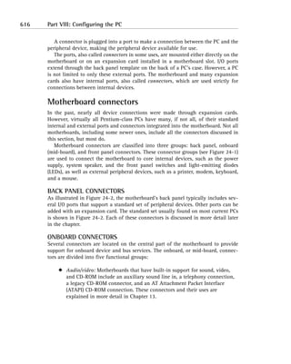
- 3. 618 Part VIII: Configuring the PC PS/2 keyboard USB One parallel port MIDI/game port port Mouse USB One serial VGA External audio connector port port jacks Figure 24-2: The common ports on the back panel of the motherboard. x Hardware power and management: These connectors attach the power supply to the motherboard, connect system and processor fans, and provide an interface for Wake on LAN or Wake on Ring technologies.
- 4. Chapter 24: Ports and Connectors 619 1 2 40 1 30 1 2 40 2 1 30 2 34 8 1 9 33 Floppy disk controller Primary IDE Secondary IDE Figure 24-3: Peripheral device connectors located on a motherboard. x Memory slots: Every motherboard includes some form of connector, mounting, or slot for memory chips or modules. Newer boards include mounting slots (shown in Figure 24-4) for RDRAM Inline Memory Modules (RIMMs) and Dual Inline Memory Modules (DIMMs). Older motherboards can have slots for Single Inline Memory Modules (SIMMs) or even Dual Inline Packaging (DIP) sockets. See Chapter 6 for more information on memory modules. x Expansion slots: The expansion slots (see Figure 24-4) on the motherboard are used to add peripheral device adapters and interface cards to the PC. Motherboards support a variety of expansion slot types, but Industry Standard Architecture/Enhanced ISA (ISA/EISA), Peripheral Component Interconnect (PCI), and Accelerated Graphics Port (AGP) are the most common. See Chapter 23 for more information on expansion cards. CONNECTORS ON THE FRONT PANEL As I describe in Chapter 8, the front panel of the system case can have a variety of LEDs and switches that attach to the motherboard for power and activity signals. The front panel connector group typically includes a connection for hard disk LEDs (power and activity), the main power On/Off button, a reset button, and a few power and grounding connections. Separately, the motherboard also has a connec- tion for the system speaker that is also mounted either on or near the front panel. The motherboard might also have an infrared (IR) or Infrared Data Association (IrDA) serial port connector as well (more on IR connections later in the section “Infrared ports”).
- 5. 620 Part VIII: Configuring the PC Expansion slots Memory slots Figure 24-4: The location on memory and expansion slots on a Slot A motherboard. External ports and connectors The external ports mounted on a motherboard’s rear panel are set by its form factor. Because most of the PCs in use today are built to the ATX form factor, most of them have a basic set of external ports. As shown in Figure 24-5, the ATX standard set includes a serial port or two, a parallel port or two, Universal Serial Bus (USB) ports or FireWire ports, a video port, a game device port, and speaker and microphone jacks. This set of ports is the real focus of this chapter. For more on form factors, read Chapter 8.
- 6. Chapter 24: Ports and Connectors 621 Game port Parallel port PS/2 ports USB ports Serial port Video port Speaker jacks Microphone jacks Figure 24-5: The standard interface ports on an ATX form factor PC. Reviewing Interface Technologies Before I go deeper into each of the interfaces listed in the preceding section, I want to review some of the “how and why” of the operations of interfaces and the dif- ferent types of data that they support. Each of the specific interfaces is explained later in the chapter. Characterizing data Data is stored on a PC in the American Standard Code for Information Interchange (ASCII; pronounced as-kee) format. ASCII defines the standard character set of PCs, including a number of special command, inquiry, and graphics characters with the upper- and lowercase alphabetic characters, special characters, and numbers of the American English language.
- 7. 622 Part VIII: Configuring the PC Table 24-1 includes a sample of the ASCII character set, including the binary and decimal values for each character. TABLE 24-1 SAMPLE ASCII CHARACTERS Character Decimal Binary Null 0 00000000 Backspace 8 00001000 Line feed 10 00001010 Form feed 12 00001100 Space 32 00100000 ! 33 00100001 Dollar sign ($) 36 00100100 0 (zero) 48 00110000 1 49 00110001 2 50 00110010 : (colon) 58 00111010 ; (semicolon) 59 00111011 ? 63 00111111 A 65 01000001 B 66 01000010 C 67 01000011 X 88 01011000 Y 89 01011001 Z 90 01011010 a 97 01100001 b 98 01100010 c 99 01100011
- 8. Chapter 24: Ports and Connectors 623 Character Decimal Binary x 120 01111000 y 121 01111001 z 122 01111010 Figuring out serial and parallel data Data is transmitted and moved in and out of the PC by using one of two formats: parallel or serial. A parallel transmission sends its data one character at a time with the bits of a character transmitted at the same time over parallel wires. On the other hand, serial data is transmitted one bit at a time over a single wire. Figure 24-6 illustrates the difference between these two transmission formats. 1 0 0 1 1 0 0 1 Parallel data 1 1 0 0 1 Serial data Figure 24-6: Character bits are sent at the same time in a parallel transmission and one bit at a time in a serial transmission. Configuring for full, half, and simplex modes A communications connection can be set up for one-way only or two-way simulta- neous transmissions depending on the transmission mode configuration established between two communicating devices. A communications line can be configured with one of three transmission modes: x Simplex: A simplex line can communicate in only one direction. A speaker wire is an example of a simplex communications line. x Half-duplex: Whereas a duplex line carries data in two directions, a half-duplex line carries data in two directions but can only transmit in one direction at a time. A citizen’s band (CB) radio is an example of a
- 9. 624 Part VIII: Configuring the PC half-duplex line — one party must wait until the other party is finished before speaking. x Full-duplex: A full-duplex line carries data in two directions simultaneously. An example of a full-duplex line is your telephone. Transmitting serial data Serial ports and connectors were used on the very first PCs to connect modems and early dot matrix printers. Serial ports transmit data one bit after the other in a series. All serial devices, cables, ports, and communications transmit their data this way. To transmit a single byte of data through a serial port, eight separate 1-bit transmissions are sent. Serial transmissions are somewhat like sending data down a pipeline just big enough for a single bit. Although an ASCII character can be defined with either 7 or 8 bits, more than this number is sent for each character, regardless of the transmission format. The extra bits are used for data integrity, data block identification, and data synchronization. BITS THROUGH THE PORT External serial devices connect to a PC through a serial or COM port. The terms serial and COM are used interchangeably, and most operating systems refer to the serial ports as COM ports, with the first serial port labeled COM1 and subsequent serial ports designated as COM2, COM3, and so on. Serial ports are also called EIA232 (Electronics Industries Association standard 232) ports or by the legacy name RS-232 (Reference Standard 232) ports. EIA is an industry association that develops standards for the communications lines, ports, and connectors used to transmit standard serial data communications. COM is a legacy term for communications. A typical PC has one serial port mounted on the motherboard. Serial ports are easily recognized because they use either 9-pin or 25-pin male D-type connectors that are designated as DA-9 and DB-25 connectors, respectively. Figure 24-5 includes a single DA-9 serial port. Because a serial transmission uses only 9-pin connectors and wires, most PCs use the DA-9 port in place of the larger DB-25. The DA-9 connector is smaller and has fewer pins, reducing both the potential for damaged or bent pins and the space required for the port area on the PC. Older PC models typically included a single DB-25 serial port on a multipurpose card that could also include a second serial
- 10. Chapter 24: Ports and Connectors 625 port, typically a DA-9 port, a parallel port, or a game port. The DB-25 connector is also popular on external modems and serial printers. SERIAL CONNECTOR PINOUTS AND CABLE CONNECTIONS Table 24-2 shows the pinouts for the DB-25 and DA-9 serial connections. Note the difference in the pin assignments between the two connectors. For a cable that has a DB-25 connector on one end and a DA-9 connector on the other end, the pins must be cross-matched to carry the signals to the appropriate pins on each end. TABLE 24-2 DB-25 AND DA-9 CONNECTOR PINOUTS Function DB-25 Pin DA-9 Pin Ground 1 Not used Transmit 2 3 Receive 3 2 RTS (Request to Send) 4 7 CTS (Clear to Send) 5 8 DSR (Data Set Ready) 6 6 Signal Ground 7 5 Carrier Detect 8 1 DTR (Data Terminal Ready) 20 4 Ring Indicator 22 9 A serial cable has as few as 2 wires and usually not more than 20 wires, but having 8 wires is very common. The wires in the cable are color coded to make connecting connectors to the cable consistent by making it easier to find the same wire on each end of the cable. The connector is attached by soldering the wires to the back of a connector’s pins. Plugging the connec- tor into a matching port completes the connection when the pins in the port make contact with the holes in the connector. With the serial connec- tion established, the PC and peripheral device can send signals back and forth to communicate and control the transmission.
- 11. 626 Part VIII: Configuring the PC Communicating asynchronously Asynchronous communications are used to connect to a printer, modem, fax, and other peripheral devices. Asynchronous transmitters and receivers operate indepen- dently and are not synchronized to a common clock signal or each other. Data blocks are separated by arbitrary idle periods on the line, as illustrated in Figure 24-7. Data Data Data Data block block block block Data flow Idle periods Figure 24-7: Asynchronous communications send data in 5-byte to 8-byte blocks that are separated by variously sized idle periods. Asynchronous data blocks are fixed in size and format. To the 8-bit ASCII character is added a start bit before the character and one or two stop bits after the character. These bits indicate the beginning and ending of each character to the receiving device. Typically, the start bit is a 0, and the stop bit is a 1. If parity is in use, the parity bit is tacked on to the data block as well. Checking parity The parity used with asynchronous communications is very much like that used with memory (see Chapter 6). The parity bit is used to force the count of 1s bits in the transmitted character to either an even or an odd number. For example, when an uppercase A is transmitted, its binary value (01000001) is transmitted. If even parity is in use, the parity bit added to the end is set to 0 (zero) because there are an even number of 1s bits in the character. If odd parity is in use, the parity bit is set to 1 to force an odd number of 1s bits in the character. If the receiving device detects an error in the number of 1 bits, it sends a request for the character to be resent. With everything added to the ASCII binary character (start bit, stop bit, and parity bit), the asynchronous data block is 11 bits long. Here is what this might look like: Transmitted character: A Start bit: 0 ASCII binary data pattern: 01000001 Even-parity bit: 0 Stop bit: 1 Transmitted data block: 00100000101
- 12. Chapter 24: Ports and Connectors 627 Using the UART A specialized integrated circuit called a universal asynchronous receiver/transmitter (UART; pronounced you-art) is used to control all serial ports and most serial device connections. A UART is located on a device adapter card, directly on the mother- board, or integrated onto a serial device’s internal controller. A UART controls all of a serial port’s or device’s actions and functions, including x Controlling all the connectors’ pins and their associated signals x Establishing the communication protocol x Converting the parallel format bits of the PC’s data bus into a serial bit stream for transmission x Converting the received serial bit stream into parallel data for transmission over the PC’s internal data bus On the PC, a UART interprets and translates the data coming into and being sent out of a serial port by examining the incoming data, looking for the start and stop bits, and verifying the parity bit counts. The UART inserts the start and stop bits and parity bit (if needed) into outgoing data. The UART also controls the data speed of the serial port or device. Table 24-3 lists the UART chips that have been used in PCs, modems, and other serial devices over the years by their identity num- bers. Most modern PCs use the 16550 UART chip, which supports speeds up to 115.2 Kbps. TABLE 24-3 UART CHIP CHARACTERISTICS Chip Maximum Speed (bps) 8250 19,200 16450 38,400 16550 115,200 16650 430,800 16750 921,600 16850 1.5 Mbps 16950 1.5 Mbps
- 13. 628 Part VIII: Configuring the PC Communicating with synchronicity Synchronous communications have a bit more overhead than asynchronous trans- missions. Synchronous transmissions have a fixed interval length between data blocks. The data blocks and the intervals of a synchronous transmission are synchronized to a clock signal that’s sent right along with the data. The communi- cating devices also carry on a running dialog that confirms and acknowledges that each data block has been received. If the acknowledgement doesn’t come back in the proper time interval, the sending device automatically sends it again. Because synchronous devices must complete one operation before beginning the next, this communications mode is very accurate. However, most serial communications on PCs use asynchronous technology. Configuring a serial port Virtually all PCs have at least one serial port, which is designated as COM1. If a PC has additional serial ports, they’re designated as COM2, COM3, and COM4. If you need to add more serial ports to a PC for some reason, you can add them one at a time or in sets of two or four. Individual serial ports require individual system resource assignments, and two such cards require two sets of system resources. However, a multiport serial card shares a single interrupt request (IRQ) among its ports with an onboard processor handling the traffic management. If a PC requires multiple serial ports, it’s probably more efficient to install a multiport card (or con- sider using USB; more on this later in the section “Utilizing a USB Interface”). Most PCs have default assignments for up to four serial ports. Table 24-4 lists the default system resource assignments for PC serial ports. COM1 shares an IRQ with COM3, and COM2 shares an IRQ with COM4, which means that you must be careful when assigning devices to COM ports to avoid competing devices. See Chapter 7 for more information on system resources. Typically, COM1 is a DA-9 male port, and COM2 (if present) is a DB-25 male port. TABLE 24-4 SERIAL PORT SYSTEM RESOURCE ASSIGNMENTS Logical Device Name IRQ I/O Address COM1 IRQ4 3F8h COM2 IRQ3 2F8h COM3 IRQ4 3E8h COM4 IRQ3 2E8h
- 14. Chapter 24: Ports and Connectors 629 Understanding Parallel Ports A parallel transmission sends the bits of a character at one time using parallel wires, which means that a character is transmitted much faster than it would be over a serial connection. The internal bus structures inside the PC use parallel transmissions, which is why a serial port needs a UART to convert the internal parallel format into a serial format for transmission over a serial line. Parallel ports are female DB-25 connectors into which a male DB-25 connector is plugged. Although originally used almost exclusively by printers, other devices have been adapted to the parallel port, including external CD-ROMs, external tape drives, scanners, and Zip drives. These devices take advantage of the bidirectional capabilities of the newer parallel port standards. The IEEE has combined parallel port standards into a single standard: IEEE 1284. This standard incorporates the two pre-existing parallel port standards with a new protocol to create an all-encompassing parallel port model and protocol standard. The separate parallel port standards included in the IEEE 1284 standard are x Standard Parallel Port (SPP): Defines a simplex parallel port that allows data to travel only from the computer to the printer. x Enhanced Parallel Port (EPP): Defines a half-duplex parallel port that allows the printer to signal that it’s out of paper, its cover is open, and other error conditions. x Enhanced Capabilities Port (ECP): Most PCs that list an IEEE 1284 port as a feature indicate support for an ECP port. The ECP standard allows bidi- rectional, simultaneous communications between a parallel device (usually a printer) and a PC. The IEEE 1284 standard also defines an ECP standard cable. When shopping for a printer ECP cable, be sure that you get an ECP cable because some EPP cables won’t work properly. Utilizing a USB Interface The Universal Serial Bus (USB) is a newer hardware interface standard that sup- ports low-speed devices (such as keyboards, mice, and scanners) and higher-speed devices (such as digital cameras). USB, which is a serial interface, provides data transfer speeds of up to 12 Mbps for faster devices and a 1.5 Mbps subchannel speed for lower-speed devices. A newer version of the USB standard, USB 2.0, supports up to 480 Mbps for data transfer speeds. A USB port offers the following features: x The flexibility of Plug and Play (PnP) devices x Standard connectors and cables with a wide variety of devices available, including keyboards, mice, floppy drives, hard disk drives, Zip and Jaz drives, inkjet printers, laser printers, scanners, digital cameras, modems, and hubs
- 15. 630 Part VIII: Configuring the PC x Automatic configuration of USB devices when they are connected x Hot swapping (USB devices that can be connected and disconnected while the PC is powered on) x The capability to support up to 127 devices on one channel Connecting with USB USB uses a unique pair of connectors and ports, as shown in Figure 24-8. USB Type A connectors are used to connect devices directly to a PC or USB hub. You’ll find USB Type A connectors on devices with permanently attached cables. USB Type B connectors are found on those devices that have a detachable cable. The cable uses a squarish Type B port on the device and connects to either a Type A or Type B socket (the cable usually has both on the other end) on the PC or hub. Figure 24-9 shows a USB Type A connector being connected to a PC USB port. Type A (Host or hub) Type B (Peripheral) Figure 24-8: The two types of USB connectors and ports. Figure 24-9: Connecting a USB device to a USB port on a PC.
- 16. Chapter 24: Ports and Connectors 631 A single USB channel can support up to 127 devices. To add more devices to a USB channel, a USB hub is used. The hubs are daisy chained to add more devices to the channel. Some newer devices, including monitors as illustrated in Figure 24-10, also have USB channels. A USB port carries .5 amps of electrical power, which is usually enough to power most low-power devices, such as a mouse or keyboard. No additional power source is required. This adds to the flexibility of the USB channel because additional devices can be added without regard to location. Those USB devices that require more power than is carried on the channel have AC/DC adapters. Digital camera External hub Scanner Hub built into monitor Figure 24-10: Multiple USB devices can be connected to a single PC. Interfacing to USB A USB interface has three essential components: x USB host: The USB host device carries operating system, chipset, and Basic Input/Output System (BIOS) support for the USB interface. Typically, the PC is the USB host. x USB hub: A USB hub serves as a collector device to cluster USB devices onto a USB channel. USB devices can be added to the channel in a tiered fashion with one hub plugged into another and a connection to the USB host from the first hub. x USB devices: Typically, a PC has only one or two USB devices plugged into its USB channels, but a USB channel is limited to 127 devices, counting USB hubs.
- 17. 632 Part VIII: Configuring the PC IEEE 1394 (FireWire) The IEEE 1394 standard defines another high-speed serial bus, officially known as the High Performance Serial Bus (HPSB) but more commonly called FireWire. This serial interface supports data speeds between 100–400 Mbps (which is the equivalent of 12 to 50 megabytes per second). Newer versions of the 1394 standard, which are being developed by the 1394 Trade Association (www.1394ta.org), are promising data speeds of 800 Mbps to 1.6 Gbps. An IEEE 1394 connector looks something like a USB connector (see Figure 24-11), except that it’s just a bit larger. Figure 24-11: A IEEE 1394 (FireWire) cable showing its connectors. The IEEE 1394 bus is similar to the USB interface in many ways. Both are high-speed, PnP, hot-swappable interface buses. One major difference is that 1394 supports isochronous (real-time) data transfers. An isochronous transfer moves data so that all of its parts arrive together, which can be very important for audio/video data, like with multimedia data or images directly from a video camera. Other dif- ferences are that the 1394 standard is a peer-to-peer interface that doesn’t require a host system, and an IEEE 1394 bus can support up to 63 external devices. Working with Wireless Ports Wireless or cordless interfaces are becoming more popular for PCs and can be used to connect peripheral devices to the PC or, as I explain in Chapter 22, even to connect the PC to a local area network. Two types of wireless connection technologies are in use on PCs: infrared (IR) and radio frequency (RF).
- 18. Chapter 24: Ports and Connectors 633 Infrared ports An IR port uses an invisible band of light to carry data between a peripheral device and a transceiver on the PC. IR light is just outside the light spectrum that humans can see. Infrared contrasts with ultraviolet (UV), which is another invisible band of light at the other end of the light spectrum. IR devices are also called IrDA devices. IrDA is the trade organization for the infrared device industry that has established the standards that define the use of an IR connection. An IrDA port is the small oval-shaped dark red plastic window built into a PC’s case. An IR device is a line-of-sight device that must have a clear, unobstructed path between its transmitter and receiver. With an IR connection, a portable PC or a per- sonal digital assistant (PDA) can connect to another PC, a keyboard, a mouse, or a printer without using a physical cable connection. Built-in IR ports (receivers) are common on portable PCs, notebooks, and PDAs, but an external IR receiver can be attached to a PC through a serial or USB port. Here are some tips for working with IR devices: x Two IR devices must have a clear, unobstructed line of sight between them. x The devices that you’re trying to connect via IR must be at least six inches apart but not more than three feet. x The transmission pattern of the IR signal is a cone about 30° wide. Make sure that the devices are oriented to one another inside the transmission cone. x Avoid competing IR devices in the vicinity — such as a TV remote control — that could interfere with the connection. Radio frequency interfaces Many cordless peripheral devices, especially those that are typically used in close proximity of the PC’s system case, use RF transmitters, receivers, and transceivers (the combination of a receiver and transmitter) to send data to the PC. RF devices include mice, keyboards, modems, and even network adapters for desktop and portable PCs. Cordless RF mice and keyboards transmit data to a receiver attached to a PC through either a serial or PS/2 connection. The operating range of these devices is around 6–10', despite claims of 50' ranges. In most cases, the performance of the cordless RF keyboard and mouse is as good as a wired device inside its effective operating distance.
- 19. 634 Part VIII: Configuring the PC RF networking devices, which are defined in the IEEE 802.11 wireless, are also known as WI-FI (wireless fidelity). Networking standards and other wire- less networking standards, such as Bluetooth and HomeRF technologies, are discussed in more detail in Chapter 22. Understanding PS/2 and DIN Connectors The 5-pin DIN connector and the PS/2 (mini-DIN connector) are the two most popular connectors for connecting keyboards, mice, and external IR and RF receivers. These connectors have become the standard for virtually all keyboards and mice on PCs. Here is a brief description of these two connectors: x 5-pin DIN connector: This connector, often called the AT-style connector, has been in use since the very first PCs. Deutsche Industrie Norm (DIN), a German standards organization, developed the round connector style used on this and the 6-pin version of this connector. Only four of the five pins are used and carry the clocking (pin 1), data (pin 2), and provide a ground (pin 4) and +5 volt (v) of power (pin 5). x 6-pin mini-DIN (PS/2) connector: This DIN-style connector (shown in Figure 24-12) is a smaller version of the 5-pin DIN connector. Keyboard and mice connections use only four of the six available pins to connect the data signal (pin 1), ground (pin 3), +5v of power (pin 4), and a clock- ing signal (pin 5). This connector, which is now the de facto standard for all cabled keyboards and mice, was first introduced on the IBM PS/2, which is why it is commonly referred to as the PS/2 connector. Nearly all mice sold today use the PS/2 connector, but some serial mice still around use the DA-9 serial connector. However, because newer PC systems rarely offer more than a single serial port and have specially designated PS/2 connectors for the keyboard and mouse, the serial mouse has all but disap- peared except on some older systems.
- 20. Chapter 24: Ports and Connectors 635 Figure 24-12: A 6-pin mini-DIN (PS/2) connector is standard on most PC keyboards and mice. Checking Out Video Connectors Regardless of the type of internal interface a video card uses (see Chapter 14 for more information on video adapters and the video interfaces), virtually all video ports use a female 15-pin DB port and connector, like the one shown in Figure 24-13. Video port Figure 24-13: The standard DB-15 VGA video port. The standard port and connector used for Video Graphics Array (VGA), Super VGA (SVGA), and Extended Graphics Array (XGA) monitor connections is the DB-15, which is also called a mini-sub D15 connector. Figure 24-14 shows the pin configuration of this connection, and Table 24-5 lists its pin assignments.
- 21. 636 Part VIII: Configuring the PC 1 2 3 4 5 6 7 8 9 10 11 12 13 14 15 Figure 24-14: The standard VGA video connector has 15 pins arranged in three rows. TABLE 24-5 PIN ASSIGNMENTS IN A VIDEO CONNECTOR Pin VGA/SVGA/XGA 1 Red video 2 Green video 3 Blue video 4 Monitor ID 2 5 Ground/Not used 6 Red video return 7 Green video return 8 Blue video return 9 Not used 10 Ground 11 Monitor ID 0 12 Monitor ID 1 13 Horizontal sync 14 Vertical sync 15 Not used
- 22. Chapter 24: Ports and Connectors 637 Dealing with Port Problems Problems with I/O ports are typically problems with the device attached to the port, a problem with the cable, a bad connector or connection, or a system resource con- flict. The following sections deal with how to troubleshoot and resolve problems with the various I/O ports. Troubleshooting a serial port When troubleshooting a serial port problem, first try connecting a different serial device to the port in question. Next, check for system resource conflicts using either the System Information applet or Device Manager on a Windows system. The System Information utility can be found by choosing Programs ¡ Accessories ¡ System Tools, and the Device Manager is best accessed by right- clicking the My Computer icon on the desktop, choosing Properties from the pop- up menu that appears, and then choosing either the Device Manager tab in Windows 9x or Me or the Hardware tab in Windows 2000 or XP. If you believe that you have a problem with the serial port, use the pinouts listed earlier in the chapter and a multimeter to check the voltages of the serial port on the PC and the continuity of the cable. RESOLVING SYSTEM RESOURCE CONFLICTS System resource conflicts cause a serial device to fail intermittently or perhaps not work at all. Other symptoms are that an existing serial device stops working when a new additional serial device is installed or the PC locks up during the boot sequence. CHECKING THE SERIAL PORT To troubleshoot a serial port problem, check the following: x Inspect the port for bent pins. Certain pins absolutely must be straight in order for the device to work properly. If you have a bent or broken pin, you should replace the connector (or cable) because the damage might compromise the connection of other pins as well. x Check the connection and connectors. Make sure that the cable wires are properly soldered to the pins in the connector and that the connector fits snuggly and correctly to the port. If any of the wires are touching each other (it takes only one strand to cause a problem), either replace the cable or repair the connector. x Test the port with another device. A serial mouse is a very good tool to have for testing serial ports. If the port is the problem and it’s mounted on the motherboard, disable it and install an additional serial port with an expansion card — that is, if you truly must use a serial port.
- 23. 638 Part VIII: Configuring the PC x Test the serial device on a different known-good serial port. Test the serial device by connecting it to another PC on which you know the serial port is working. If the device works, you know that the problem is not the device. However, you still have some troubleshooting to do on the original PC to isolate the problem. x Ensure that the cable is appropriate for the device. Some serial devices can’t use a straight-through or null modem cable. Check the pin and configuration requirements of the device and use the appropriate cable. x Check the length of the serial cable. You might hear stories of successfully using longer cable lengths, but the nominal maximum length for a serial cable is 50' between two devices. Beyond 50', you might suffer attenua- tion (the distance at which the signal begins losing its strength) and begin seeing data errors. x Check the BIOS settings. COM ports can be enabled and disabled in the BIOS setup configuration data. Make sure that the port is enabled. A disabled port will not work. x Check the Windows Device Manager or System Information applet for system resource conflicts. An IRQ conflict is the most common error with serial devices. Remember: Only one active device should be using an IRQ at a time. x Check the software setup. In most cases, application software is used to manage or control the serial device, such as dialup software for a modem. Check the configuration of the software and the settings that it uses to configure the serial device. Dealing with serial port system resource conflicts The symptoms for a system resource conflict on one or more serial ports are fairly straightforward. Here are the most common: x The modem on COM3 fails when the serial mouse on COM1 is used or vice versa. x The system locks up when the serial devices on COM2 and COM4 are used at the same time. There are many variations of these two problems, but they boil down to a system resource conflict and probably a specific IRQ conflict. If the device on COM2 is having or causing the problem, it should be reconfigured either to a different COM port or IRQ. If the COM ports were installed on a multiport I/O controller card, change the configuration of the card through its jumpers, as specified in the card’s documentation.
- 24. Chapter 24: Ports and Connectors 639 Troubleshooting a parallel port Because parallel ports are virtually featureless and either work or don’t work, most parallel port problems are caused by the physical part of the connector or port (bent pins or blocked holes), the cable (wrong type: SPP, EPP, or ECP), or the attached device. Here are some steps that you should use to troubleshoot and isolate a parallel port problem: x Check for resource conflicts. There is an outside chance that the problem is a system resource conflict, but this problem is usually caused by another device that was just added to the PC. See Table 24-6 for the default system resource assignments made to parallel (LPT) ports. TABLE 24-6 PARALLEL PORT SYSTEM RESOURCE ASSIGNMENTS Port IRQ I/O Address DMA Channel LPT1 IRQ7 378h DMA 3 (ECP capabilities) LPT2 IRQ5 278h NA x Check the cable and connectors for physical problems. If a commercial printer cable is in use, make sure that it’s tightly fitted on both ends to the port and printer. If a homegrown cable is in use, make sure that the cable wires are properly soldered to the pins in the connector and that the connector fits snuggly and correctly to the port. If any of the wires are touching each other (it takes only one strand to cause a problem), either replace the cable or repair the connector. If the parallel port is attached to a pass-through port where two parallel devices are connected in tandem (like on a scanner or Zip drive), I suggest disconnecting one of the devices and testing again. The problem could be the pass-through connector. x Verify that the device is working properly. To test the printer, try printing a plain text file to avoid issues on the printer itself. If the printer appears to be receiving data but doesn’t print, try the printer on another PC. If it still doesn’t work, you know that the problem is with the printer. Otherwise, check to make sure that you have the proper device drivers and configuration for the printer or other device. x Verify system resource settings. If the PC is equipped with more than one parallel (LPT) port, use the Windows Device Manager or System Information applet to rule out system resource conflicts.
- 25. 640 Part VIII: Configuring the PC x Check the BIOS setup configuration. You can set the IRQ assigned to the LPT ports in the BIOS setup configuration data. Make sure that it’s set to IRQ7 (default) for LPT1 and IRQ5 for LPT2. If the problem is with the port assigned to IRQ5, check for a conflict with the sound card. x Verify the communications mode of the parallel port. Check the device’s documentation to verify that the port is configured to the correct commu- nications mode (SPP, EPP, ECP). Many printers require at least an EPP mode to be configured to the port in the BIOS Setup configuration data. x Check ECP settings. If ECP mode is enabled on a parallel port, it can cause system resource conflicts that are avoided by other parallel modes. Although the LPT ports are assigned an IRQ, most parallel devices (such as printers) don’t use it. However, if ECP mode is enabled and the IRQ has been assigned to another device, it can cause a resource conflict. ECP mode also requires a DMA channel and could be in conflict with the sound card. x Verify the device drivers. Check the device manufacturer’s Web site for newer versions of the device driver. Make sure that the device drivers in use are compatible with the operating system in use on the PC. Many Windows 9x drivers won’t work on a Windows 2000 system. Dealing with printing (parallel port) problems In most cases, if a printer is producing garbled or distorted print or if part of a page or image is missing, look for a problem with either the hardware or the software associated with the printer itself. However, if all appears to be right with the printer, the LPT port can cause one or two things as well. To diagnose this problem, check the following: x Check the print mechanism on the printer. Although the focus is on the cable and the connector, perhaps the printer itself isn’t functioning. This is a good place to start when printing problems occur. The problem is rarely on the parallel port or the cable. x Verify that the most current printer driver is in use. The printer driver must be compatible with the printer as well as the operating system on the PC or the network. An installation disk or CD-ROM comes with most printers, but you should visit the manufacturer’s Web site to download the most current driver for the printer and operating system. x Try changing the parallel port mode. Not all printers are compatible with the latest standards. Some printers can have problems with the ECP communication mode and work much better with EPP mode. Check the printer’s documentation to verify its communications mode requirement and configure the port accordingly in the BIOS setup configuration. x Verify that the cable is appropriate. Check the cable for problems, sharp bends, cuts, indications that it might have been crushed, or loose connector
- 26. Chapter 24: Ports and Connectors 641 heads. Also check to see whether the cable is the right one for the printer. If the printer requires an IEEE 1284-certified ECP printer cable and the cable in use is only an EPP, you could have a problem. Troubleshooting a USB connection If you’re having problems with a USB port, here are some things that you can check to make sure that the USB ports are active on the system. The first place to look is in the Windows Device Manager to ensure that the USB ports are actually installed on the system. Figure 24-15 shows where the USB ports are listed in the Windows Device Manager. Figure 24-15: Universal Serial Bus controller information in the Windows Device Manager. If all appears to be normal in the Device Manager (no conflicts or missing drivers), check the following: x Check the device connections. Although it might seems obvious, this should always be the first troubleshooting step when dealing with device problems. Make sure that the device is connected to the PC — and if it requires power, that it’s plugged into a power source. Some USB devices (such as keyboards and mice) get their power from the USB channel, but others require additional power. x Enable the USB connection. Make sure that the USB ports are enabled in the BIOS setup configuration data. Although the PC should be shipped from the factory with its USB ports enabled, you never know until you try to use one. It could be that the PC has USB ports, but the BIOS system doesn’t support them. In this case, you might need to upgrade the BIOS (see Chapter 4) to support USB ports, if such an upgrade is available.
- 27. 642 Part VIII: Configuring the PC x Verify the devices installed. If both the host controller and the root hub are installed (and listed on the Device Manager), all is well. However, if one or the other is missing, the problem is in the .INF file used to install the device drivers. Try removing the device from the Device Manager and then clicking the Refresh button to have the system automatically detect the devices. If this fails, open the device’s Properties window and update the device driver, which you’ll find in the USB.INF file in the INF folder (a subfolder to the Windows folder), and then re-install it. x Check for system resource conflicts. The USB host controller shares its IRQ with other devices. Rarely does this cause a problem; however, on occa- sion, this can cause the USB device from being recognized when attached to the USB port. If this happens, you should reassign the USB host con- troller to a different IRQ (providing that one is available). Assigning an IRQ to the USB host controller Use these steps to force the USB host controller to a different IRQ setting: 1. With the Device Manager displayed, double-click Computer at the top of the device tree. This displays the Computer Properties window, shown in Figure 24-16. Figure 24-16: The Windows Computer Properties window. 2. On the Reserve Resources tab, click the Add button, enter the number of the IRQ currently in use by the USB host controller, and then click OK to close the window. 3. On the Device Manager window, select the USB host device and click the Remove button. 4. Restart the system. The USB host controller will be detected and assigned to a different IRQ.
- 28. Chapter 24: Ports and Connectors 643 5. Return to the Device Manager’s Computer Properties windows and remove the reservation of the IRQ reserved in Step 2. 6. Click OK on each succeeding window and restart the PC when requested. Enabling IRQ steering The USB host controller requires IRQ Steering to be enabled on the PCI bus in order to support multiple devices. To enable IRQ steering, perform the following steps: 1. From the Device Manager, choose the PCI Bus entry and then click the Properties button. 2. Choose the IRQ Steering tab and then select the check box for Use IRQ Steering as illustrated in Figure 24-17. Figure 24-17: The IRQ Steering tab in the Windows PCI Bus Properties dialog box. 3. Under the Use IRQ Steering check box are four IRQ steering options: The first two and the fourth settings should be marked. 4. Click OK on each succeeding window and restart the PC when requested.
- 30. Part IX PC Operating Systems CHAPTER 25 The Windows Operating System CHAPTER 26 Unix and Linux Operating Systems
- 32. Chapter 25 The Windows Operating System IN THIS CHAPTER I know that this is essentially a hardware book, but a PC technician absolutely must be able to install and configure an operating system on a user’s PC because it’s just a part of the overall installation and configuration process. As much as you and I would like to concentrate on hardware and the really challenging physical elements of a PC, in effect, there is no PC without its operating system (OS). Okay, I should include application software along with the OS to make a PC truly usable, but there is so much application software and so little time. In this chapter, I cover the following: x Installing and configuring Windows 98 (and Me) x Installing and configuring Windows 2000 x Installing and configuring Windows XP x Starting Windows in Safe mode MY VIEW OF OPERATING SYSTEMS is the product of my experience, which tells me that when talking about operating system software, the first name out of the box is Microsoft, which automatically leads to Windows. Microsoft Windows has the largest installed base of any of the OS providers, so it’s essential that a PC techni- cian have a working knowledge of the processes used to install and configure this system. No, I haven’t forgotten about other operating systems, but because this book is for PC technicians, I’m not covering network operating systems (NOS) — and, in a fairly bold stand, I’m not including Apple Computer’s operating systems (Mac OS) as well. However, Chapter 26 does cover some essential Unix/Linux topics that every PC technician should know. 647
- 33. 648 Part IX: PC Operating Systems Looking at the Different Versions of Windows Microsoft Windows has been around for nearly a decade and in that time (and despite a somewhat shaky start) has grown to be the most popular PC OS in the world. Regardless of what you, I, or the Justice Department think of it, the Microsoft Windows (hereafter, just plain Windows, please) OS is as much a part of the PC world as the hard disk on which it resides. Over the years, Windows has released several versions. Some versions were just patches and fixes to the previous version, whereas others, such as Windows NT, 98, and XP, have effectively re-invented the system’s look — and to a lesser extent, its function. I think little is to be gained by covering the versions prior to Windows 98 in this book. It always surprises me how much information is still available on the Web about Windows 3.x and Windows 95. If you need further information on these systems, I suggest that you use Google or a similar search engine to hunt for what you need. In the following sections, I cover the installation and configuration processes (along with a few troubleshooting tips) of Windows 98 (occasionally referred to as Windows 9x, when the information also covers Windows 95 OEM SR2), NT, Millennium Edition (Me), 2000, and XP. In the case of Windows NT, 2000, and XP, the discussion is limited to desktop (Professional or Home) versions rather than the Server versions. Installing and Configuring Windows 98/Me For an obsolete operating system, Windows 98 is sure hanging on. Many users and IT departments are approaching Windows OS updates with the attitude that if it ain’t broke, don’t fix it. If you ever need to install Windows 98 for the first time on a PC (or reinstall it after some catastrophe), follow the steps in the next few sections. For the sake of simplicity, I use Windows 98 in this section to indicate Windows 98, 98 SE, and Me. Installing Windows 98/Me Using a clean installation is the best way to install Windows 98. A clean installa- tion means that the hard disk drive on which you wish to install the system has
- 34. Chapter 25: The Windows Operating Systems 649 been partitioned, formatted (see Chapter 10 for more information on formatting and partitioning a hard disk drive), and cleaned of all pre-existing data. If another OS has been on the PC, you should definitely create a full backup of the system prior to deleting or formatting the old partitions. Nothing goes wrong in 99 percent of the cases, but that 1 percent can ruin you. To install Windows 98, use the following procedure: 1. Before beginning the installation, assemble the following items: s The Windows 98 CD-ROM release media. s A valid Windows 98 product key ID number. s A Windows 98 boot disk (just in case things do go wrong during the installation) — see “Creating a Windows 98/Me boot disk” later in this chapter. s Current and up-to-date device drivers for the peripheral devices and controller cards in the PC. With these items assembled, you’re ready to start the installation. 2. Insert the Windows 98 boot disk in the floppy disk drive and power the PC off and on to boot the system from the floppy disk drive. If the system bypasses the floppy disk drive and boots from the hard disk, enter the Basic Input/Output System (BIOS) setup program and change the boot disk search sequence to add or move the floppy disk drive into the first position. 3. After the Windows 98 Setup menu appears, insert the Windows 98 CD in the CD-ROM drive. The Windows Setup menu gives you three installation options: s Start Windows 98 Setup from CD-ROM s Start computer with CD-ROM support s Start computer without CD-ROM support 4. Choose the second option, which will load the CD-ROM device drivers and make it accessible. When the drivers are installed, a list of the detected hard disk drives on the PC is displayed, followed by a DOS command prompt.
- 35. 650 Part IX: PC Operating Systems 5. Repartition the system hard disk, if needed, and format the partitions that you wish to clean for the installation. You aren’t required to repartition the hard disk(s). If you’ve had trouble with them in the past, you might wish to do so. 6. At the command prompt, enter A:>FORMAT C: /Q to format the C: disk partition. Remember, DOS commands aren’t case sensitive; you can enter them as upper- or lowercase characters. If you’re using a different partition, replace the C: with the appropriate drive designation. Understand that formatting the hard drive will erase all data and programs on the hard disk partition. When the formatting is completed, you have the option of naming the hard disk partition or pressing the Enter key to skip this step. Unless you’re planning to install an application system in a particular parti- tion, such as DB2, Sybase, or the like — or will be dual-booting the PC with a Linux system — there really are no hard and fast rules for naming partitions. However, make sure that the application software or second operating system doesn’t specify a particular partition naming convention.
- 36. Chapter 25: The Windows Operating Systems 651 7. At the command prompt, enter the drive designator for the CD-ROM drive. It should typically be something in the range of D:, E:, or F:. I’m assuming that it is D:; if not, use the drive designator assigned by the system. Press Enter to move to the next step. 8. At the command prompt, enter D:win98setup. The Windows 98 Setup program starts and displays a message that it will now run the ScanDisk utility. Accept this action (by pressing the Enter key) and then start a scan of the hard disk partition for any media errors. 9. When the ScanDisk completes, the Setup program displays installation options. Choose the Typical Installation option to start the file installation process. 10. When the basic installation is completed, restart the system as requested, making sure that you remove the boot disk from the floppy drive before doing so. 11. After the system restarts, install the device drivers for any motherboard- related components, including Peripheral Component Interconnect (PCI) bus mastering, interrupt request (IRQ) routing, and Accelerated Graphics Port (AGP) miniport drivers, if needed. These drivers are typically found on the CD that shipped with the mother- board, but if not there, they can be downloaded from the Web beforehand. The best place to find drivers for the motherboard-related components is on the manufacturers’ Web sites. 12. Before installing the peripheral device drivers, run the Disk Defragmenter utility to further clean up the system. Disk Defragmenter can be found by choosing Start ¡ Programs ¡ Accessories ¡ System Tools. After the device drivers are installed, you’ve completed the installation of the Windows 98 operating system and just about its entire configuration. Any remaining configuration steps are usually proprietary or locally defined, so follow the instructions for each device to the letter. Controlling a Windows 98 setup The Windows 98 Setup program has a variety of parameter switches that you can use to control the function and actions of the setup process. Table 25-1 lists the major options available to you.
- 37. 652 Part IX: PC Operating Systems TABLE 25-1 WINDOWS 98 SETUP SWITCHES Value Action /? Lists the available switches for the setup program. /na Bypasses the program check based on the value substituted for n. 0 = Default. 1 = No Windows-based program checking; MS-DOS programs are blocked. 2 = No MS-DOS program checking; Windows programs are blocked. 3 = No Windows or MS-DOS program checking. /nd Ignores the presence of a Migration.dll file and forces the setup program to overwrite newer files. The exception is that Windows Setup will keep newer “x32” files. (See /na for values of n.) /nf Omits prompting to remove the floppy disk drive (when installing from a bootable CD). (See /na for values of n.) /nm Bypasses the minimum hardware requirement test (486DX66 and 16MB RAM). (See /na for values of n.) /d Bypasses using any existing Windows configuration files (Win.ini and System.ini). /ie Bypasses the Windows 98 Startup Disk wizard screens, and the WindowsCommandEDB folder is not created. /ig Allows Windows 98 to be installed on legacy Gateway and Micron PCs with older BIOS. /in Bypasses the installation of the network wizard pages, and the network setup routines won’t run. /ir Bypasses the updating of the Master Boot Records (MBRs). /m Bypasses the setup sound (.wav) files. /n Bypasses the mouse drivers to run setup without a mouse. (This switch is the letter n and not a value.) /t<dir> Assigns a location for the setup temporary files. Configuring Windows 98 Actually, after Windows 98 is installed, there really isn’t that much more to config- ure. However, the following sections include a few things that you might want to tweak to ensure that it operates like it should.
- 38. Chapter 25: The Windows Operating Systems 653 DEALING WITH DEVICE MANAGER ERRORS Immediately after installing a Windows system of any version, check the Windows Device Manager (see Figure 25-1) to ensure that no hardware errors have been cre- ated in the process. On a Windows 9x system, the Device Manager is accessed by right-clicking the My Computer icon on the desktop, choosing Properties from the pop-up menu that appears, and then choosing the Device Manager tab of the Properties window. Figure 25-1: After a Windows installation, check Device Manager for hardware errors. If a device problem exists, Device Manager flags either the device class (such as hard disk controllers, mouse, or display adapters) or a specific device (such as the PS/2-compatible mouse port) with one of three symbols (not counting the symbol used to mark an operating device): x Exclamation point inside a yellow circle: Indicates a device that’s in a problem state. A device in a problem state could be working, yet some- thing isn’t quite right with it — for example, an incompatible device driver. x Red X: Indicates a device that’s been disabled by either the system or the user. A disabled device is physically installed in the system and has system resources assigned to it but doesn’t have a protected mode driver installed. x Blue i: Indicates that automatic resource settings aren’t in use on the device. This isn’t necessarily a problem but more of a reminder. If a device is flagged with one of these symbols, look at the device’s properties (click the Properties button) to see whether a conflict exists or a system error code has been assigned to the device. Here are a few of the Device Manager’s error codes and their appropriate resolutions:
- 39. 654 Part IX: PC Operating Systems x Code 1: The system hasn’t configured this device. Follow the instructions in the Device Status box for removing the device from the Device Manager, restarting the PC, and running the Add New Hardware Wizard from the Control Panel. x Code 2: The device wasn’t loaded by the device loader (DevLoader). This error is typically displayed when the device is a Root Bus DevLoader (for example, PCI or BIOS). It typically includes the message Windows could not load the driver for this device because the computer is reporting two <type> bus types (Code 2). Contact your com- puter manufacturer to get an updated BIOS for your computer. The <type> will be ISAPNP, PCI, BIOS, EISA, or ACPI. If the device is not a Root Bus DevLoader, the message is The <type> device loader(s) for this device could not load the device driver (Code 2). To fix this, click Update Driver to update the device driver. In this case, <type> is FLOP, ESDI, SCSI, and the like. x Code 3: The device driver is bad or the system is running low on memory. Update the device driver or delete the device from Device Manager and use the Add New Hardware Wizard from the Control Panel to add the device again. x Code 4: The .inf file for the device is incorrect or the registry entry is corrupted. Remove the device from the Device Manager and use the Add New Hardware Wizard from the Control Panel to add the device again. You’ll find around 35 of these error codes, some indicating very critical prob- lems and some only minor system nuisances — but all should be investigated and resolved. Visit the Micosoft Knowledge Base at http://support.microsoft.com/ default.aspx?scid=KB;en-us;q125174 for a complete listing of the error codes. If a device’s problem appears to be that a real-mode driver is being used in place of a protected-mode driver (the driver you really want to have loaded), check the entries in the Ios.log file in the Windows folder, which can only be found if you’re experiencing this problem. Real-mode device drivers are 16-bit drivers compared with the 32-bit .vxd (protected-mode) drivers. Because Windows log files are in text format, you can use the Notepad utility to open and read them. The first line in the Ios.log file, if present, should indicate why the protected-mode driver didn’t load. If the Mbrint13.sys file is mentioned, you can be almost sure that a virus is causing the problem (that is, unless you’re using a device driver that replaces the Master Boot Record).
- 40. Chapter 25: The Windows Operating Systems 655 ACCESSING THE CD-ROM AFTER INSTALLING WINDOWS 98 OR ME If you cannot access the CD-ROM driver after installing Windows 98/Me, the prob- lem is linked to a dual-channel Integrated Drive Electronics (IDE) controller on the system. Use the following steps to resolve this problem: 1. Choose Start ¡ Settings ¡ Control Panel, click the System icon, and then choose the Device Manager tab. 2. Expand the Hard Disk Controllers group. 3. Click the IDE controller to highlight it, click the Properties button, and then choose the Settings tab on the window that opens. 4. In the Dual IDE Channel Settings drop-down list box (see Figure 25-2), choose the Both IDE Channels Enabled option from the list and then click OK. Figure 25-2: The Windows IDE Channel Setting dialog box is used to control the availability of IDE channels. 5. Restart the PC. PHANTOM USB Even if the PC’s USB ports aren’t in use, you might want to enable two BIOS settings (in the BIOS setup configuration data) anyway: x OnChipUSB: For some reason, this setting on the Chipset Settings menu allows the system to shut down properly and display the It is now safe to turn off your computer message on some PCs.
- 41. 656 Part IX: PC Operating Systems x Assign IRQ for USB: This setting on the Plug and Play (PnP)/PCI Configuration menu allows a system shut down to complete properly on some motherboards, but especially on motherboards manufactured by Abit Computer Corporation. OPTIMIZE THE SWAP SPACE On PCs with 128MB or more of memory, the size of the hard disk swap file is less critical than on PCs with low memory. So to optimize (conserve) the hard disk space used by the virtual memory swap file, make the following change to the registry: 1. From the Windows Notepad utility, open the SYSTEM.INI file from the Windows directory. 2. In the section following the subtitle [386Enh], insert the following entry: ConservativeSwapfileUsage=1 3. Save the file and restart the PC. MINIMIZE THE DISK CACHE The disk cache — the buffer allocated in system memory to the caching function of the hard disk drive — can slow down the system and cause some low memory prob- lems. This problem is especially noticeable on PC’s with 16MB or less of RAM that run Windows 98/Me. To control the minimum and maximum amount of memory allocated to the hard disk cache on a PC, use the following steps: 1. Open the SYSTEM.INI file in the Windows folder from the Notepad utility. 2. In the [vcache] section, locate and modify, or add if needed, these two lines: MinFileCache=0 MaxFileCache=4096 On PCs with more than 16MB of RAM, you can increase the MaxFileCache to about 25 percent of the total RAM size. For example, if you have 256MB of RAM, you could set MaxFileCache=64000000.
- 42. Chapter 25: The Windows Operating Systems 657 Installing and Configuring Windows 2000 Professional If you’ve recently passed the Microsoft Certified Systems Engineer (MCSE) 70-210 (Installing, Configuring, and Administering Microsoft Windows 2000 Professional) exam, you can probably skip this section. However, if you’ve never installed or configured the Windows 2000 Professional (Pro) operating system on a PC, the fol- lowing information could be helpful. Understand that the most common form of installing Windows 2000 is as an upgrade, typically over Windows 98/Me. Installing Windows 2000 Pro Installing Windows 2000, at least in terms of installing the basic operating system, is actually quite easy. Just follow two basic steps: Insert the release CD in the CD-ROM drive and then restart the PC. A small run-time version of Windows 2000 is copied into RAM and started, which then loads and starts the setup program. You need to answer a few questions and enter the software ID key (found on the release booklet), but that’s about it, especially for Windows 2000 Pro. VERIFYING WINDOWS 2000 MINIMUM REQUIREMENTS The minimum system requirements for installing Windows 2000 are the following: x Processor: A 133 MHz or higher Pentium-class CPU; Windows 2000 supports either single or multiple processors. x Memory: At least 64MB of RAM, but more is better. x Hard disk space: At least 2GB with 650MB of available free space. CHECKING WINDOWS 2000 HARDWARE COMPATIBILITY Before installing Windows 2000 (NT or XP, as well), you should verify that the hardware, software, and BIOS of the PC are compatible, which means that they have been tested and found to perform like they should on a Windows 2000 system. Microsoft includes a list of compatible devices and systems in its hardware com- patibility list (HCL). For the latest list, visit www.microsoft.com/windows2000/professional/howtobuy/upgrading/compat This Microsoft Web site provides search tools for computers, hardware devices, and software that you can use to see whether a PC and its components will work properly with Windows 2000 Pro.
- 43. 658 Part IX: PC Operating Systems Here are two reasons why you should check the BIOS first: x The existing BIOS version might not support the advanced power man- agement and device configuration features of Windows 2000. In order to take advantage of the power management features in Windows 2000, the PC must be compliant with Advanced Configuration and Power Interface (ACPI) BIOS. x The wrong BIOS version on a PC could cause the PC to stop working like it should, with Windows 2000 installed or not. See Chapter 4 for information on PC BIOS and the procedures used to update a BIOS system. PREPARING TO INSTALL WINDOWS 2000 Windows 2000 can be installed three different ways: x Clean install: Install Windows 2000 as the only operating system on a PC on an empty or formatted hard drive. This section focuses on the clean installation procedure. x Dual boot install: Install Windows 2000 on a PC with another operating system, such as Windows 98, Windows NT 4.0, or Linux, so that the PC can be booted to either system from a menu of operating system choices displayed when the PC boots. Windows 2000 must be installed either on a separate hard disk drive or into a separate partition from the other operat- ing system. x Upgrade install: A PC running Windows 9x or Windows NT 4.0 can be upgraded to Windows 2000. This type of installation replaces the existing operating system files with new ones. To install Windows 2000 using a clean install, you first need to prepare the hard disk drive for it. The three different ways to accomplish this task are the following: x Using Windows 2000 boot disks: To create a set of four Windows 2000 boot disks, you must first boot the system (this can be done on any com- puter, not just the one on which you’ll be installing Windows 2000) to a DOS prompt using either a Windows 9x or MS-DOS boot disk. See “Creating Windows 2000 boot disks” later in the chapter for information on creating the boot disks. Insert the first of the four boot disks and reboot the PC. The installation will then proceed.
- 44. Chapter 25: The Windows Operating Systems 659 x Using a Windows 9x boot disk: This is the faster of the two methods that you can use, but it will only work if the boot disk has SMARTDRV.EXE on it: Without it, the installation can take hours instead of minutes. After booting the PC to the boot disk, use the DOS FDISK command to create one or more partitions on the hard disk drive. Reboot the system, enabling CD-ROM support, and then use the DOS FORMAT command to format the system (active) partition, which is usually the C: partition. Next, enter the DOS command SYS C: to make the C: drive bootable (this step might or might not be necessary, but it provides a bit of insurance that the system will reboot to the active partition). See “Creating a Windows 98Me boot disk” later in the chapter for information on creating a boot disk. RUNNING WINDOWS 2000 SETUP The following steps detail the process used to install Windows 2000: 1. Before inserting the Windows 2000 release CD in the CD-ROM drive, enter the BIOS setup program and set the CD-ROM driver as the first boot device. See the earlier section “Installing Windows 98/Me” for instructions on how this is done. 2. Place the Windows 2000 CD in the CD-ROM drive and restart the PC. If the hard disk drive is partitioned and formatted, the message Hit Any Key to Boot from CD-ROM is displayed. 3. The AutoRun feature on the CD starts up and runs the setup program and begins to load the device drivers needed to proceed. 4. Continue through the Welcome to Setup menu and read the license agree- ment. If you agree to abide by the license agreement, which you should, press F8 to continue. The next display is the partition screen where you can indicate the area of the disk on which you’d like to install Windows 2000. You can assign Windows to an unpartitioned part of the disk or set up partitions on an unpartitioned disk drive. See “Preparing to install Windows 2000” earlier. The format screen displays where you can specify how you wish to format the disk drive space, meaning which file system you wish to use. 5. Normally, you should choose FAT from the list if you’re installing Windows 2000 on a standalone PC, or you can choose one of the other options available, provided that you know what they are and when you should use them. See “Configuring Windows 2000” later in this chapter for more information on files systems.
- 45. 660 Part IX: PC Operating Systems After you make your choice, the setup program confirms it and begins formatting the partition. On a very large disk drive (more than 4GB), this can take awhile. After the partition space is formatted, the PC restarts and displays the Setup Wizard. 6. Continue through the first wizard screen to start the hardware detection phase of the installation. After the system has detected and configured the attached and compatible hardware, it runs through a series of screens to set the regional settings; the user’s name and organization; product key ID; administrator’s pass- word; and the date, time zone, and local time. If the PC is networked, Windows 2000 then detects and installs the networking settings. The typical settings work just fine for nearly all workstation PCs. 7. When asked which type of installation you wish for Windows 2000, unless you have specific reasons not to, you should click the Express Setup button. The Custom Setup option requires knowledge of Windows 2000 and its elements. 8. When the Setup Wizard completes, click the Finish button to restart the PC. After the system restarts, the Network Identification Wizard starts. You can configure the PC’s network ID and workgroup at this time or wait and do it later. 9. The basic installation and configuration are done. If needed, you should enter the Control Panel and configure the PC for the user or the network, depending on the peripherals, dialup, networking, and features desired by the user. Configuring Windows 2000 For most users, after the Windows 2000 installation process is completed, their PC is essentially good to go. However, you can do a few things to optimize the system for performance and to avoid future problems. SETTING MAXIMUM VOLUME AND FILE SIZES FOR WINDOWS 2000 Windows 2000 supports three different file systems: File Allocation Table (FAT), FAT32, and New Technology File System (NTFS). When defining the partition size for Windows 2000, use the information in Table 25-2 as a guide.
- 46. Chapter 25: The Windows Operating Systems 661 TABLE 25-2 WINDOWS MAXIMUM VOLUME AND FILE SIZES Max Files File Windows Max Volume Max File (Folders) per System Versions Size Size Volume FAT All Windows versions 2GB on Windows 95; 4GB 512 4GB on all later versions FAT32 .NET 2003, XP, 2000, 2TB 4GB 65,534 98, 95 OSR2 NTFS .NET 2003, XP, 2000, 256TB Volume 4,294,967,295 NT (NTFS 4 only) capacity The use of long filenames reduces the volume and file size numbers. Check the documentation of the Windows version in use. CONVERTING A FAT FILE SYSTEM TO NTFS ON WINDOWS 2000 Which file system a system should use depends primarily on the application pro- grams running on it. Many legacy programs will only run with an FAT file system. However, if the decision is made to convert an FAT or FAT32 file system to NTFS, you don’t need to reformat the disk partitions affected, but you should back up the data on the file system to be converted. You would convert an FAT or FAT32 file system to NTFS because it’s more pow- erful than FAT or FAT32, it’s required for hosting Active Directory, and it supports many very important security features of Windows 2000, such as domain-based security. To convert the FAT or FAT32 file system on a Windows 2000 system to NTFS, use the following steps: 1. Open a command prompt window by entering cmd in the Run dialog box (from the Start menu) and then clicking OK. 2. At the command prompt that appears, enter convert drive_designator: /fs:ntfs.
- 47. 662 Part IX: PC Operating Systems Installing Windows XP Nearly all newer PCs come with Windows XP pre-installed, but that doesn’t mean that you can just replace perfectly working PCs with new ones just to get an upgraded system. As simple as that might sound, the money issue typically prevents it from being that easy. Upgrading to Windows XP Not every system can be upgraded to Windows XP. Table 25-3 lists the versions that can be updated to Windows XP Home or Windows XP Pro, which are the ver- sions that I’m assuming you would install on a user’s PC. TABLE 25-3 WINDOWS VERSIONS UPGRADEABLE TO WINDOWS XP Windows Version XP Home XP Pro Windows 3.x No No Windows 95 No No Windows 98 Yes Yes Windows NT Workstation 4.0 No Yes Windows 2000 Pro No Yes Windows Me Yes Yes Windows XP Home - Yes Windows XP Pro No - With the Windows XP version, Microsoft has made Upgrade Advisor avail- able. This online utility checks a PC for its compatibility for an upgrade to Windows XP. In addition, Upgrade Advisor checks your system for required updates and then downloads and installs them. You can find more informa- tion on Upgrade Advisor at www.microsoft.com/windowsxp/pro/ howtobuy/upgrading/advisor.asp. Upgrading to Windows XP from an eligible Windows version (see Table 25-3) is actually fairly easy. Insert the Windows XP CD-ROM; when you’re asked which
- 48. Chapter 25: The Windows Operating Systems 663 type of installation you’d like to perform, choose Upgrade. If all is well, the Windows XP setup program will perform the upgrade installation automatically. Installing Windows XP Pro or Home editions To install Windows XP on a clean PC (one that’s had its hard disk drives formatted clean), use the following steps: 1. Boot the PC from the Windows XP release media CD. 2. If the PC has any devices not supported by Windows XP (XP doesn’t have drivers for them), obtain the drivers before starting the installation and press F6 when the XP installation first starts up. The setup program begins loading the Windows XP files and displays a series of screens, most of which you should continue through (accepting the End-User License Agreement [EULA] along the way). Eventually, a screen displays that asks you to select the hard disk partition on which you wish to install Windows XP. 3. Choose the partition and then click Next to proceed. If you wish to have two operating systems on the PC, you should create two hard disk drive partitions, one for the existing operating system and one for Windows XP, either beforehand or at this time. 4. If you’re installing Windows XP into a partition that has existing data, be sure to choose the Keep Current File System Intact option on the next screen displayed. 5. If the installation is on a clean PC (recommended), select the partition and then click Next. 6. On the next screen displayed, select either a quick format for FAT or NTFS as the file system for the PC. s If no data on the PC requires security, choose FAT because FAT is the faster file system choice. s Choose NTFS if security is required for the existing data or for future data to be stored on the hard disk drive. After choosing the file system appropriate for the PC, the Windows XP Setup continues to load its files. After it copies the files that it needs for the configuration that you’ve indicated, the system restarts itself.
- 49. 664 Part IX: PC Operating Systems After rebooting, you’ll be asked for the Regional and Language options along with a few bits of other information for its files and its product ID key. Because Windows XP assumes that it will be networked, the remainder of the setup requests a workgroup or domain and an automatic check for the type of network on the PC. 7. The final installation step asks you to create the user name account for the user or users of the PC. XP creates user name accounts without pass- words, so that’s something you must do later via the Users icon of the Control Panel. Starting Windows in Safe Mode If a PC has a serious boot problem, such as freezing during startup or a device that fails to load its device driver, you should boot Windows into Safe mode as the first step in your troubleshooting process. In Safe mode, Windows loads only the device drivers that it needs in order to function, which excludes most of the peripherals attached to the PC. The process used to start Windows in Safe mode varies by its version. The following sections detail the steps used to start Safe mode for the dif- ferent Windows versions. All Windows versions, with the exception of Windows 3.x and Windows NT, can be started in Safe mode. Opening Windows 9x/Me/2000 in Safe mode To start Windows in Safe mode, the first couple of steps depend on whether Windows is running. Here’s what to do x If Windows is running: 1. Close all open programs. 2. Choose Shut Down from the Start menu. 3. Click Restart and then click OK. x If Windows is not running: 1. If the PC is powered on, turn off the power switch. 2. After a few seconds, power the PC on.
- 50. Chapter 25: The Windows Operating Systems 665 The next set of actions is common to all versions of Windows (including Windows XP): 1. Watch the screen and its display carefully. As soon as the Starting Windows bar appears at the bottom of the display, begin tapping F8. This should cause the Options menu (called the Advanced Options menu on Windows 2000) to display. 2. Select the Safe Mode option (typically the first option on the menu) and press Enter. The system will start up in Safe mode, which might take a few minutes to complete. 3. After you complete your troubleshooting, restart the PC, and it will return to normal mode. Opening Windows XP in Safe mode If you can start the PC in Windows, here are the recommended steps to use to set up Windows XP to restart into Safe mode (SAFEBOOT): 1. Close all running application programs. 2. Run the System Configuration Utility by entering msconfig into the Run dialog box (from the Start menu) and then clicking OK. The System Configuration Utility window (see Figure 25-3) displays. Figure 25-3: The Windows XP System Configuration Utility. 3. As shown in Figure 25-3, mark the /SAFEBOOT check box and then click OK.
- 51. 666 Part IX: PC Operating Systems 4. When prompted to restart the PC, click the Restart option. The PC restarts and loads Windows XP into Safe mode. 5. After you complete your troubleshooting and wish to return Windows XP to its normal mode, run the msconfig utility again, clear the /SAFEBOOT check box, and then restart the PC. Another way that you can reach Safe mode on a Windows XP system is to press the F8 key during startup, but you have to do it at just the right time or you’ll have to try again. That’s why I prefer the /SAFEBOOT method — I never seem to hit the key at just the right time. Creating a Windows Boot Disk Creating a diskette to use to reboot a Windows system when it can’t otherwise be started is always a good idea. Users will think that you can walk on water if you can boot a PC that has been unbootable. Plus, it’s tough to fix a PC that you can’t get up and running. Creating a Windows 98/Me boot disk To create a Windows 98 boot disk, access the Add/Remove Programs icon on the Control Panel and choose the Startup Disk option to create the disk. The boot disk that’s generated (on your blank diskette) provides all the required files, including CD-ROM support, needed to boot a Windows 98/Me system. I recommend that you copy the DOS commands FDISK, FORMAT, and SMARTDRV to the boot disk, if you will be using it to install either Windows 2000 or Windows NT 4.0. Creating a Windows NT boot disk To create a Windows NT boot disk, use the following steps: 1. Use the Windows Explorer to open the i386 folder on the Windows NT release media CD or in the WINNT folder on the hard disk drive. 2. Format a blank floppy disk and copy the following files to the diskette: s boot.ini s ntdetect.com
- 52. Chapter 25: The Windows Operating Systems 667 s ntldr s Also copy to the diskette any Small Computer System Interface (SCSI) or other devices that you wish to access after you boot the PC with the boot disk that you’re creating. Creating Windows 2000 boot disks To create a Windows 2000 Pro boot disk, you need to have four 1.44MB diskettes and the Windows 2000 Pro release media CD available. Follow these steps to create the boot disk: 1. Insert the CD in the CD-ROM drive. 2. Open the Run dialog box (from the Start menu) and then click the Browse button to browse the CD. 3. Open the Boot Disk folder on the CD and double-click the makebt32.exe program. 4. Click OK to start the program, which will guide you through the steps needed to create the boot disks. Obtaining Windows XP setup boot disks Windows XP setup boot disks are created through a file that you must download from the Microsoft Web site. Visit the following URL for information on which file to download for your XP version and instructions on creating boot disks: http://support.microsoft.com/default.aspx?scid=KB;en-us;q310994
- 54. Chapter 26 Unix and Linux Operating Systems IN THIS CHAPTER Surprisingly enough, for some people, there is life outside the world of Windows. Users who (for myriad reasons) don’t want to use Windows can opt to install and use Unix (which is not an acronym for anything) or Linux (likewise) as an alterna- tive to Windows. I don’t propose in this chapter to give you an in-depth Linux tutorial, but I do want to provide you with the following information on Linux hardware support so that if you encounter a PC running Linux, you have some idea how to identify the source of a problem: x An overview of Linux hardware systems x Dealing with Linux hardware issues x Managing hardware configurations in Linux UNIX AND LINUX (hereafter I use Linux, which is the most common of the two on PCs, to represent both) are among the most popular operating systems in the world on several levels of computing. Unix can be found on supercomputers, mainframes, minicomputers, network servers, and specialized networked workstations. Linux is more often found on network servers and frequently on standalone user PCs. Linux has grown in popularity because of its source accessibility, which is especially popular with operating system purists and operating system hackers. Unix is still very expensive to run at the PC level (as much as $1,500 per machine), but the freely distributed Linux is available in an open source form at no cost. Commercial versions of Linux are also available from Caldera, Red Hat, Slackware, and others. Understanding a Linux Installation If you’re a Windows-trained technician who has never had the fun of working with MS-DOS or the like, Linux might seem a bit overly complicated to you when you first encounter it. Unless the PC is running X-windows (a Windows-like user inter- face for UNIX and Linux systems) or its equivalent, you’ll probably be greeted by its standard command prompt, which is typically a dollar sign ($). 669