R&S (rohde-schwarz) SMB100A microwave signal generator
•Transferir como PPTX, PDF•
0 gostou•128 visualizações

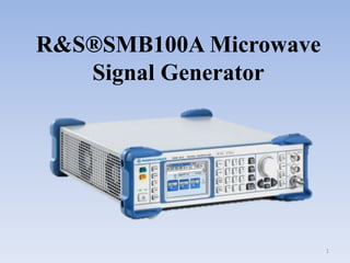
R&S®SMB100A microwave signal generator with a frequency range up to 40 GHz provides outstanding spectral purity and high output power. In addition, it features easy operation, comprehensive functionality and low cost of ownership.

Recomendados
Mais conteúdo relacionado
Mais procurados
Semelhante a R&S (rohde-schwarz) SMB100A microwave signal generator
Semelhante a R&S (rohde-schwarz) SMB100A microwave signal generator (20)
Último
Último (20)
R&S (rohde-schwarz) SMB100A microwave signal generator
- 2. AIM To give the basic idea about R&S®SMB100A Microwave Signal Generator 2
- 3. Content • Brief description • Front Panel Overview. • Rear Panel Overview. • Putting into Operation. • Shutting Down the Instrument. 3
- 4. Brief description • A signal generator is an electronic device that generates repeating or non-repeating electronic signals in either the analog or the digital domain. These generated signals are used as a stimulus for electronic measurements. • R&S®SMB100A microwave signal generator with a frequency range up to 40 GHz provides outstanding spectral purity and high output power. In addition, it features easy operation, comprehensive functionality and low cost of ownership. 4
- 5. Front Panel Overview The front panel of the R&S SMB consists of the VGA display, some utility keys (left side) and the hard key area with connectors and control interfaces (right side). 5
- 6. Standby LEDs and Standby Key The standby LEDs and the ON/STANDBY key are located in the bottom left corner of the front panel. The ON/STANDBY key toggles the instrument between standby and ready state (indicated by the standby LEDs). The standby LEDs indicate the instrument states as follow: ● the green LED (left) is on when the instrument is ready for operation, ● the yellow LED (right) is on in the standby mode. 6
- 7. Utility Keys PRESET Sets the instrument to a defined state LOCAL Switches from remote control to local (manual) control. SETUP Opens the "Setup" dialog for configuring presetting's. FILE Activates the menu for storing or loading files INFO Displays status messages, error messages and warnings. WINBAR Toggles between the diagram and active menus. HELP Displays context-sensitive help text. 7
- 8. Display • The display clearly shows all main settings and signal generator states. The display is divided into the following sections: ● Frequency and level display with info line – Frequency and level settings containing offset. – Status messages – Brief error messages. To access an window with detailed information for a message, use the INFO key. 8
- 9. Setup Keys These keys provide direct access to the settings in the header of the instrument for fast setting the RF signal. FREQ Activates frequency entry. LEVEL Activates level entry. ON/OFF TOGGLE Switches highlighted elements or a function block on and off. BACKSPACE Deletes the character to the left of the cursor. 9
- 10. Display Keys DIAGRAM Brings the block diagram to the foreground. Active menus are minimized. ESC The function of this key depends on the current cursor position. ● Closes all kinds of dialog boxes, if the edit mode is not active. ● Quits the edit mode, if the edit mode is active. ● Switches between different entry fields of a menu. MOD ON/OFF Switches the modulations on and off. RF ON/OFF Switches the RF signal on and off. "RF OFF" is displayed in the header next to the "Frequency" field. 10
- 11. Keypad for data entry The keys in the data entry keypad are used to enter alphanumeric data and units. Data entry keys are only enabled while the cursor is placed on a data input field in a dialog. Their function depends on the data type of the input field. 11
- 12. Rotary Knob and Navigation Keys The rotary knob and the arrow keys are alternative control elements for data variation and navigation in the graphical user interface. The rotary knob has several functions: ● Increases (clockwise direction) or decreases (counter- clockwise direction) numeric values at a defined step width in editing mode ● Moves the cursor, e.g. to a function block in the block diagram ● Scrolls within lists, tables or tree views ● Acts like the ENTER key, when it is pressed. 12
- 13. NAVIGATION KEYS UP/ DOWN KEYS In a numeric edit dialog box, increase or decrease the instrument parameter. LEFT/ RIGHT KEYS In an alphanumeric edit dialog box, move the cursor forward and back. 13
- 14. Front Panel Connectors Input for external modulation signals. Output for internal LF modulation generator signal. Output for RF signal. 14
- 16. AC SUPPLY AND POWER SWITCH USB (universal serial bus) interface of type B (device USB). This interface can be used for remote control of the instrument. USB (universal serial bus) interfaces of type A (host USB). ● Connection of peripherals such as mouse, keyboard, etc. ● Connection of memory stick for file transmission ● Firmware update LAN CONNECTOR Ethernet interface 16
- 17. Putting into Operation 1.Apply 230 AC into the power socket. 2.Select the power switch to on position. 3.Connect the RF cable to the output port. 4.Press the power button switch and wait few second for booting. 5.Press ‘FREQ’ button and select the frequency by using key according to your requirement. 6.Press ‘LEVEL’ button and select amplitude by using key according to your requirement. 7.Press ‘RF ON/OFF’ button, to deliver the RF Signal according to the selected setting. 17
- 18. Shutting Down the Instrument 1. Press the ON/STANDBY key to save the current setup, shut down the operating system and set the instrument to standby state. The yellow LED must be on. 2. To switch off the power, press the main power switch to position 0 (Off).None of the front-panel LEDs should be on. 18
- 19. 19