unwanted pregnancy Kit [+918133066128] Abortion Pills IN Dubai UAE Abudhabi
Duyar Elemanlar St fr ex-donma-termostat
1. Data Sheet Ref: 90501213
Issue: 5.1
ST-FRE
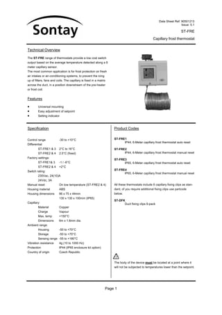
Capillary frost thermostat
Technical Overview
The ST-FRE range of thermostats provide a low cost switch
output based on the average temperature detected along a 6
meter capillary sensor.
The most common application is for frost protection on fresh
air intakes or air-conditioning systems, to prevent the icing
up of filters, fans and coils. The capillary is fixed in a matrix
across the duct, in a position downstream of the pre-heater
or frost coil.
Features
• Universal mounting
• Easy adjustment of setpoint
• Setting indicator
Specification Product Codes
Control range -30 to +10°C ST-FRE1
IP44, 6-Meter capillary frost thermostat auto reset
Differential:
ST-FRE1 & 3 2°C to 16°C ST-FRE2
ST-FRE2 & 4 2.5°C (fixed) IP44, 6-Meter capillary frost thermostat manual reset
Factory settings:
ST-FRE3
ST-FRE1& 3 -1 / -6°C IP65, 6-Meter capillary frost thermostat auto reset
ST-FRE2 & 4 +2°C
Switch rating: ST-FRE4
IP65, 6-Meter capillary frost thermostat manual reset
230Vac, 24(10)A
24Vdc, 3A
Manual reset On low temperature (ST-FRE2 & 4) All these thermostats include 6 capillary fixing clips as stan-
Housing material ABS dard, of you require additional fixing clips use partcode
Housing dimensions 86 x 75 x 44mm below.
130 x 130 x 100mm (IP65)
ST-DFK
Capillary: Duct fixing clips 6-pack
Material Copper
Charge Vapour
Max. temp +150°C
Dimensions 6m x 1.8mm dia.
Ambient range:
Housing -50 to +70°C
Storage -50 to +70°C
Sensing range -55 to +180°C
Vibration resistance 4g (10 to 1000 Hz)
Protection IP44 (IP65 enclosure kit option)
Country of origin Czech Republic
The body of the device must be located at a point where it
will not be subjected to temperatures lower than the setpoint.
Page 1
2. Data Sheet Ref: 90501213
Issue: 5.1
ST-FRE
Capillary frost thermostat
Connections
1. The ST-FRE should only be installed by a competent,
suitably trained technician, experienced in installation 1
with hazardous voltages. (>50Vac & <1000Vac or 1 Common
>75Vdc & 1500Vdc) 2 2 Rising temperature
4 Falling temperature
2. Ensure that all power is disconnected before carrying out 4
any work on the ST-FRE.
3. Maximum cable is 2.5mm², care must be taken not to
over tighten terminals. Dimensions
4. Mount the ST-FRE on a flat surface or using the ST-
FRE/BRK using the screws supplied.
CAUTION: If other screws are used, ensure that they do
not penetrate into the control more than 8mm. Prevent
distortion of the housing and ensure that there is suffi-
cient room to adjust controls. You should avoid mounting
the thermostat where it will be subjected to mechanical
vibration.
5. Fix the capillary in the sensing location, not more than
100mm of the capillary should be located outside the
control temperature. Unit trips when 300mm of capillary
falls below setpoint temperature. The body of the device
must be located at a point where it will not be subjected
to temperatures lower than the setpoint.
6. The capillary should be secured using capillary clips
(supplied) to prevent excessive vibration and must not
be twisted or kinked. Any bends in the capillary must
have a minimum radius of 25mm.
7. Feed the electrical cable through the rubber grommet,
alternatively this can be replaced with a standard PG
13.5 cable gland.
8. Make electrical connections as required (terminal torque
settings 1.2Nm max.).
9. Set the switching point and differential (ST-FRE1 & 3
only) by adjusting the screws on top of the ST-FRE.
10. To test the switch, use the check-out lever to manually
override the electrical contact position.
Page 2