

Recomendados
Mais conteúdo relacionado
Mais procurados
Mais procurados (20)
Semelhante a 111 120
Semelhante a 111 120 (20)
Mais de Enhmandah Hemeelee
Último
Último (20)
111 120
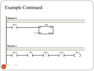
- 2. Example Continued This part is like the second part. Watering the trees is started when previous section are finished. The time for this section is 18 second which is added to 14 seconds counted before and now it is written as 3200 ms with 10ms increment. You can see when both Q0.1 and Q0.2 are off the third part (Q0.3) is started. 112
- 3. Example five This example is based on a parking lot with a PLC which counts the number of cars that enter and exit and if the parking lot is about to be full, PLC sends a signal to a electronic board to say that the parking is full. The system is also utilizing a infrared sensor to open the gates with remote control.(The capacity of this parking lot is assumed to be 5 cars.) 113
- 4. Solution 114
- 5. Example Continued In this example input I0.0 open the entrance gate and input I0.1 opens the exit gate. I0.0 and I0.1 are both infrared sensors which will be activated by remote control. In addition sensor I0.2 count the number of cars entering the parking lot and sensor I0.3 counts the cars leaving . The switch I0.4 is used to reset the system. If a total number of 5 cars enter this parking lot, counter C1 send a signal to the electronic board Q0.2 to show that the parking is full. 115
- 6. Programmable logic control A PLC has many "input" terminals, through which it interprets "high" and "low" logical states from sensors and switches. It also has many output terminals, through which it outputs "high" and "low" signals to power lights, solenoids, contactors, small motors, and other devices lending themselves to on/off control. In an effort to make PLCs easy to program, their programming language was designed to resemble ladder logic diagrams. Thus, an industrial electrician or electrical engineer accustomed to reading ladder logic schematics would feel comfortable programming a PLC to perform the same control functions. 116
- 7. Program design of PLC Design objective PLC selection and resource allocation I/O address assignment Wiring Programming 117
- 8. Layout of Intersection Trafic Lights North G Y R G Y R West East R Y G R Y G South 118
- 9. I/O address assignment Serial number 1 I0.0 Start swich 2 I0.1 Stop 3 I0.2 emergency stop button 4 Q0.0 North-South Green 5 Q0.1 North-South Yellow 6 Q0.2 North-South Red 7 Q0.3 East-west Green 8 Q0.4 East-west Yellow 9 119 address Notes Q0.5 East-west Red
- 10. AC220 N L Q0.0 I0.0 I0.1 Q0.1 I0.2 Q0.2 24V(L+) Hardware Wiring PLC CPU224 Q0.3 AC/DC/ RLY Q0.4 1M Q0.5 M 1L 2L 120 AC220 AC220