SlideShare uma empresa Scribd logo
1 de 29
Baixar para ler offline
Valve Types and Features
          The three basic functions of valves are: 1. to stop flow, 2. to keep a constant direction of flow, and 3. to regulate
          the flow rate and pressure. To select the correct valve to fulfill these functions properly, an outline of the
          different types of valves and their features is given below.

           Butterfly valve                                 Check valve                                     Gate valve                               Globe valve                                      Ball valve


                         Open                                         Open
                                                                                                                                                                                                          Open
                                                                                                                                                            Open
                                                                                                                      Open


                         Closed
                                                                      Closed                                                                                                                             Closed
                                                                                                                                                            Closed
                                                                                                                      Closed

           Valve shaped like a                            For use when flow is only in                  Like its name implies, the                The globe-shaped body                        Valve stopper is ball-
           butterfly.                                     one direction.                                gate is lowered to cut off                controls the fluid into a S-                 shaped.
           Tight shut-off and can be                      Lightweight disc allows                       the path of flow.                         shaped flow.                                 For use as an on/off valve
           used as a control valve.                       vertical installation.                        For use as an on/off valve                Tight shut-off and can be                    (not suitable as a control
           Little resistance to flow                      High operating speed                          (not suitable as a control                used as a control valve.                     valve).
           (allows smooth flow).                          prevents water hammer.                        valve).                                   Large resistance to flow                     Little resistance to flow
           Optimal for automated                                                                        Little resistance to flow                 (does not allow smooth                       when fully open (allows
           operation with a low                                                                         when fully open (allows                   flow).                                       smooth flow).
           operating torque and 90                                                                      smooth flow).                             Much power is required to                    Optimal for automated
           degrees operating angle.                                                                     Long stroke requires time to              open and close the valve                     operation with a 90 degrees
           Lightweight and compact                                                                      open and close; not suitable              (not suitable for large                      operating angle.
           (large diameter models are                                                                   for quick operation.                      sizes).                                      Advanced technology is
           also available).                                                                                                                                                                    required to manufacture
                                                                                                                                                                                               ball.


          Comparison of butterfly valves with other valves (using 100mm diameter TOMOE 700G model valve)

            Butterfly valve and globe valve                                            Butterfly valve and ball valve                                          Butterfly valve and gate valve

                Item              Butterfly valve          Globe valve                      Item            Butterfly valve          Ball valve                     Item             Butterfly valve           Gate valve
          Pressure loss ξ)
                      (                     0.3                     1.5         Pressure loss ξ)
                                                                                            (                         0.3               0.05                Pressure loss ξ)
                                                                                                                                                                        (                      0.3                0.2
          Flow characteristics            Equal %            Equal %            Flow characteristics           Equal %               Quick open             Flow characteristics           Equal %             Quick open
          Rangeability                      :
                                           10 1                  :
                                                                30 1            Rangeability                       :
                                                                                                                  10 1                  :
                                                                                                                                        3 1


             Comparison of Cv value                                          Comparison of pressure loss                                      Inherent flow characteristics
             (Butterfly valve=1)                                             (Butterfly valve=1)
                                                                                                                                                                                                         △P=Constant
                                                                                                                                                  100
                                                                                                    5                                                                         n
                                                                                                                                                                            pe
                                                                                                                                                                       icko
                                                                                                                                                                    Qu
                                                                                                                                                   80


                                                   2
                                                                                                                                                   60
                                                                                                                                                                                           r
                                                                                                                                                                                        ea
                                                                                                                                                                                     Lin
                                                                                                                                           Cv %


                                                            1.5
                                                                                                                                                   40
                                                                                                                                                                                                    l%
                                                                                                                                                                                                  ua


                         1                                                         1
                                                                                                                                                                                                Eq


                                                                                                                            0.7                    20


                                  0.2                                                                        0.2
                                                                                                                                                    0
                                                                                                                                                        0      20             40               60         80       100
                     Butterfly    Globe            Ball     Gate                Butterfly          Globe       Ball          Gate
                      valve       valve           valve     valve                valve             valve      valve          valve                                               Valve opening % 

Data

Data-01                                                                                                        463
Valve Sizing Procedures
It is essential to understand the valve sizing formula and selection procedure when determining the size of a
valve. The following is the proper selection procedure. The valve sizing calculation is based on ISA.


1. Judge if the flow condition is subcritical or critical based on the given flow condition.


2. Calculate the Cv value by putting the data into an appropriate formula.


3. Select the size of the valve using the Cv value chart. Consider the following points when sizing the valve.
   q A proper adjustment of the Cv calculation should be made based on the piping adjustment coefficient
      Fp if a valve is located between reducers.
   w If the result of the Cv calculation is over 80% compared to the full Cv value, select a valve one size
      larger.
      Example: For fresh water with P1 = 0.3 MPa, P2 = 0.25 MPa, flow rate = 100 m3/h, the calculated Cv
      will be 164. If 80 mm, 507V is selected, the rated Cv is 176. The calculated Cv (164) is over 80% of
      rated the Cv (176) in this case. We recommend 100 mm, 507V.
   e If no △P is given, 5 to 10% of the pump outlet pressure should be used as the assumed △P for valve
      sizing.


                                                                                                                  Data

                                                        464                                                      Data-02
Cv Value Calculation
                          Cv value calculation


Data

Data-03                      465
Symbol Legend

Symbol
Cv: Valve flow coefficient
FL: Pressure recovery coefficient
G: Specific gravity of gas                    (Air = 1)
Gf: Specific gravity at valve-inlet temperature          (Water = 1 at 15 degrees C)
P1: Valve-inlet pressure                    (kPaA)
P2: Valve-outlet pressure                   (kPaA)
△P: Pressure difference across valve [P1 — P2]           (kPa)
Pc: Critical pressure                      (kPaA)
Pv: Saturated vapour pressure of liquid at valve-inlet temperature (kPaA)
△PS: Max. DP for sizing
      • Working conditions: Outlet pressure is higher than vapour pressure.

   △PS = P1 — Pv                                                  (kPa)
   • Working conditions: Outlet pressure is equal to or lower than vapour pressure.

              0.96−0.28 Pv
   DPS = P1 —           Pv                                         (kPa)
                        PC
q: Volume flow rate of liquid                  (m3 / h)
Q: Volume flow rate of gas [At 15 degrees C, 1 atm]        (m3 / h)
              288
 = Nm3/h×
              273
T: Fluid temperature [273 + degrees C]             (K)
Tsh: Degree of superheat                     (degrees C)
  = T — Tc
Tc: Saturated vapour temperature at valve-inlet pressure (K)
W: Mass flow rate (T / h) = (1,000 kg / h)


                                       Calculation for piping geometry factor


Fp=


Fp: Piping geometry factor
Cv: Valve flow coefficient
d: Valve size (mm)
D1: Inlet pipe size (mm)
D2: Outlet pipe size (mm)


                                          Calculation for modified Cv value

CvR = Fp Cv

CvR : Revised Cv value


                                                                                        Data

                                                           466                         Data-04
Conversion Formula for Reference
          Pressure loss coefficient                 Cv value       Length of pipe


                                                                    D: Inside diameter of pipe (cm)
                                                                    Q: Flow rate               ( /min)
                           D: Inside diameter of pipe (cm)
                                                                   △P: Pressure difference     (kPaA)

          Cv value          Kv value                               Reference: For performance appraisal of fire
                                                                             safety and disaster prevention
          Kv value is used in Europe.                                        equipment, the equivalent pipe length
                                                                             is measured based on the flow rates
          It shows the flow rate (m3/h) of drinking water at a               in the table below.
          pressure of 1 bar and temperature of 5−30 degrees C.
                                                                     Nominal dia. Flow rate(r/min)
                                                                       50mm              800
                                                                       65mm              900
                                                                        80mm           1350
          Pressure loss coefficient               Kv value             100mm           2100
                                                                       125mm           3300
                                                                       150mm           4800
                                                                       200mm           8500
                        D: Inside diameter of pipe (cm)
                                                                       250mm          13000
          Cv value         Av value                                    300mm          19000


          Av value is a SI unit.                                   Pressure difference


                                                                     : Pressure loss coefficient
                                                                   △P: Pressure difference              (kPa)
                                                                     : Acceleration of gravity 9.8 m/sec2
                                                                     : Specific gravity (water = 1000) (kg/m3)
                                                                    V: Flow velocity                     (m/sec)


Data

Data-05                                                      467
Guidance for Vacuum Use
                   Nominal dia.                 Usable vacuum (kPaA)                      Valve seat leak
 Valve type          range                                                                                                                              Remark
                     (mm)       10 to 50 degrees C 50 to 80 degrees C 80 to 100 degrees C   (kPa R/h)
                                                                                                ・

                       80-200                0.133                  0.133                    1.33                      1.0
     304A            250-300                 1.33                   1.33                     2.66                      8.0
                     350-600                 2.66                   3.99                     5.32
                       80-200                1.33                   1.33                     2.66                      8.0
     302A            250-300                 1.33                   3.99                     5.32                    14.0
                     350-600                 2.66                   3.99                     5.32
                                                                                                                                        Special gland structure required.
                       40-200                1.33                   1.33                     2.66                    14.0
     302Y
                     250-300                 2.66                   3.99                     5.32
                       50-200                1.33                   1.33                     2.66                    14.0
     337Y
                     250-300                 2.66                   3.99                     5.32
                       40-200                1.33                   1.33                     2.66                      1.0
     304Y
                     250-300                 2.66                   3.99                     5.32                      8.0
     846T              65-200                                                                                                           Leakage increases if heat cycle
                                             0.133                  1.33                     2.66                      0.3
     847T              50-300                                                                                                           and open/close frequency is high.

     731P              50-200                0.133                  1.33                     13.3                      0.3
     732P            250-300                 0.133                  2.66                     26.6                      3.0

     731X
                     350-600                 2.66                   13.3              Use not possible.                5.0
     732X

                       40-200                13.3                   26.6              Use not possible.                3.0
     700G            250-300                 26.6                   53.2              Use not possible.                5.0
                     350-600                 39.9                   66.5              Use not possible.

                       50-200                13.3                   26.6              Use not possible.                3.0
     705G
     704G            250-300                 26.6                   53.2              Use not possible.                5.0
                     350-600                 39.9                   66.5              Use not possible.

                     125-300                 26.6                   53.2              Use not possible.                5.0
     722F
                     350-600                 39.9                   66.5              Use not possible.

                     250-300                 26.6                   53.2              Use not possible.                5.0
     841T
                     350-600                 39.9                   66.5              Use not possible.
     842T            350-600                 39.9                   66.5              Use not possible.
Leak amounts are predicted values based on testing at room temperature with new valves. If you will be using in a range that exceeds the above table, please consult us.


                                                                                                                                                                             Data

                                                                                           468                                                                              Data-06
Velocity Calculation
                                                             Velocity limitation

          Velocity limitations are shown below:
                         Type of fluid                  Velocity limitation (continuous operation)
                             Replaceable rubber seat                    3 m/s
               Liquid
                             Vulcanized rubber seat                     5 to 6 m/s
                         Gas, vapour                                    120 to 200 m/s
                             Saturated steam                            50 to 80 m/s
               Steam
                             Superheated steam                          80 to 120 m/s

          * Velocity limitation varies depending on the valve models. Please consult us for further information.


                                                       Pipe line velocity calculation

          For liquids


          For gases and vapours


          For steam

          Where:
          V: Flow velocity (m/sec)
          Q: Flow rate
             Liquid (m3/h)
             Gas [At 15 degrees C, 101325 Pa] (m3/h)

              = Nm3/h

          Steam (kg/h)
          U: Specific volume of valve-outlet (m3/kg)
          D: Nominal size (mm)
          P2: Valve-outlet pressure (kPaA)
          T: Temperature (degrees C)


Data

Data-07                                                              469
Noise Prediction Methods and Countermeasures
                                                                   Noise measuring method

The following are methods recommended by ISA.


            Note: Parts surrounded by dotted lines are optional.


Fig. 1 Laboratory test unit by ISA-RP59.1                                          Fig. 2 Position of microphone in plant by ISA-RP59.2


                                         Noise calculation formula for 507V and 508V Types


                                                                                                                                           Data

                                                                             470                                                          Data-08
Noise calculation formula for valves other than 507V and 508V Types

          Formulas are in accordance with those introduced by ISA.


          For gases


          When liquid cavitation is generated


          Where:
          SP: Noise value [sound pressure level at 91cm]                 (dBA)
          Cv: Flow coefficient in actual conditions
          FL: Pressure recovery coefficient
          P1: Valve upstream pressure                                     (kPaA)
          P2: Valve downstream pressure                                   (kPaA)
          m: Weight of pipe wall                                           (kg/m2)
          η Apparent valve orifice coefficient (butterfly valve: n = 1.4)
           :
          TL: Transmission loss → Except for valves releasing directly into the air.


              *P2crit: P1 — FL2 (P1 — Pv)               (kPaA)
          Pv: Vapour pressure of liquid               (kPaA)
          X: Conversion fraction of mechanical output

                                X = 1 even if X is bigger than 1.

          SG: Gas property factor
          η:  Acoustical efficiency coefficient (Refer to page Data-11.)

          Note: When the difference between Kc and FL2 exceeds 10% of Kc, substitute Kc for FL2.


Data

Data-09                                                         471
Specific gravity SG                                                                             Specific gravity SG

                                                                                                      +2
             Saturated steam                                                                          +1
             Superheated steam
             Natural gas                                                                               0
             Hydrogen                                                                                 −1
             Oxygen


                                                                          Specific gravity SG (dBA)
             Ammonia                                                                                  −2
             Air                                                                                      −3
             Acetylene
                                                                                                      −4
             Carbon dioxide
             Carbon monoxide gas                                                                      −5
             Helium                                                                                   −6
             Methane liquid
             Nitrogen                                                                                 −7
             Propane                                                                                  −8
             Ethylene
                                                                                                      −9
             Ethane
                                                                                                      −10
Refer to the graph on left for fluids other than those above.                                            0         10       20      30        40       50
                                                                                                                          Molecular weight


                                                                    Weight of pipe (m)
m=A×t
  *A: Basic weight (kg/mm m2)
                         ・
   [Steel pipe: 7.85, stainless steel pipe: 7.93]
   t: Pipe thickness (mm)
                                                                                                                                                   (kg/m2)
          Nominal dia.                                                                                       m
      mm               inch               SGP              Sch20      Sch40                                Sch60         Sch80       Sch10S        Sch20S
      40               1 1/2              27.5                  −      29.0                                 35.3          40.0        22.2          23.8
       50                2                29.8              25.1       30.6                                 38.5          43.2        22.2          27.8
       65              2 1/2              33.0              35.3       40.8                                 47.1          55.0        23.8          27.8
       80                3                33.0              35.3       43.2                                 51.8          59.7        23.8          31.7
      100                4                35.3              38.5       47.1                                 55.7          67.5        23.8          31.7
      125                5                35.3              40.0       51.8                                 63.6          74.6        27.0          39.7
      150                6                39.3              43.2       55.7                                 73.0          86.4        27.0          39.7
      200                8                45.5              50.2       64.4                                 80.9          99.7        31.7          51.5
      250               10                51.8              50.2       73.0                                 99.7         118.5        31.7          51.5
      300               12                54.2              50.2       80.9                                112.3         136.6        35.7          51.5
      350               14                62.0              62.0       87.1                                118.5         149.2           −         −
      400               16                62.0              62.0       99.7                                131.1         168.0           −             −
      450               18                62.0              62.0      112.3                                149.2         186.8           −             −
      500               22                62.0              74.6      118.5                                161.7         205.7           −             −
      550               20                 −                74.6      124.8                                174.3         224.5           −             −
      600               24                 −                74.6      137.4                                193.1         243.4           −             −


                                                                                                                                                              Data

                                                                          472                                                                                Data-10
η......Acoustical efficiency factor


Data

Data-11                   473
Valve noise reduction countermeasures

Aerodynamic noise is discussed here.
Noise can be reduced at the following points:

1 Noise source
2 Sound insulation

When selecting a countermeasure, controllability of process, initial cost and maintenance cost should be
considered along with noise evaluation and noise type.
Various factors should be discussed between the customer and manufacturer. Please refer to the section
 Calculation of Estimated Cavitation and its countermeasure to reduce and prevent cavitation noise.

Countermeasures for noise source

There are two countermeasures for noise source.

(1) Adoption of low noise valve
    q 507V and 508V types:                            Max. possible reduction is 10 dBA.
    w Globe type low noise valve:                     Max. possible reduction is 15 to .30 dBA.

(2) Countermeasure at valve downstream side
    q Insert resistance plate:                        Max. possible reduction is 15 dBA.


          Example of low noise unit


Sound insulation                                                   Example: Pipe lagging materials

This countermeasure does not reduce sound generation
itself.

q Increase of pipe wall thickness (pipe schedule)
  If it doubles, 5 dBA can be reduced.


w   Soundproof lagging
    In this countermeasure, piping is covered with layers of  
    heat insulating materials (rock wool), lead plates, or iron
    plates, etc.


e Prepare sound insulating box or wall
  In order to reduce noise effectively, combine the various
  methods mentioned above.
                                                                                                            Data

                                                         474                                               Data-12
Calculation of Estimated Cavitation
                                               Cavitation generation in butterfly valves

          Cavitation is caused by low pressure areas in fluids. There are four causes of low pressure areas:


                                         Fig. 1 Butterfly valves in nearly closed position
          (1) Fluid is compressed, contraction flow exists, and flow velocity is increased. Then, pressure reduces.
          (2) Low pressure area inside vortexes at valve-outlet side.
          (3) Low pressure area is produced at the boundary between the fluid flowing at high velocity and objects such
              as the protruding portion of the valve-moulded surface, heads of taper pins, and hubs, etc.
          (4) When the valve body or disc is vibrating at high frequency, the flow is disturbed and air bubbles form in the
              fluid.

          The main causes of cavitation generation in butterfly valves are (1) and (2).
          Thus, when the valve is nearly closed, the flow passes over the upper and lower edges of the disc as shown in
          figure. 1. The low pressure area can be caused when high flow velocity is created.


                                                                   VC (vena cont racta)


                                                         Fig. 2 Orifice flow


          Figure 2 shows orifice flow corresponding to valve flow. The contracted part is called vena contracta. The
          relation between pressure and flow rate is shown in figure 3.

                                                                                                           VC
                                                                                                      P1
          When fluids flow at high velocity and pressure drops below
          the saturated vapour pressure, air bubbles are produced.
          They are carried away toward the valve downstream side,
                                                                                  Pressure (P)


                                                                                                                           Flow (V)


                                                                                                                   P2
          and then, as surrounding water recovers its original
          pressure, air bubbles break instantaneously (approx. 1/1000
                                                                                                 Pv
          sec) and produce a strong impact force (200 to 500 atm). If
          air bubbles break near a substance, the impact applies
          great stress on both the outside and inside of the                                               Pvc

          substance, and causes damage to the surface.

                                                                                  Fig. 3 Pressure and flow rate relation


Data

Data-13                                                         475
Cavitation generation process in butterfly valves and formula to estimate it


There are many stages in cavitation generation, as follows.

                 Flow conditions                      Pressure conditions                  Explanation


               Fig. 4 Normal flow
                               VC
 P1

                                            P2


 Pv
                                   Pvc                                        Normal flow means turbulent flow.
                                                                              In this stage, valve flow rate increases
                                                                              in proportion to the square root of the
                                                                              differential pressure.


              Fig. 5 Cavitation flow

                                                                              Cavitation flow has three stages corre-
 P1                           VC
                                                                              sponding to the increase in differential
                                                                              pressure.
                                                                              a. Incipient cavitation stage
                                            P2                                b. Critical cavitation stage
                                                                              c. Full cavitation stage
 Pv                                                                           Noise and oscillation may cause dam-
                                                                              age to the valve and downstream-side
                                                                              piping.
                             Pvc


                                                                              This occurs when pressure on the valve
               Fig. 6 Flashing flow                                           downstream side drops below the va-
                                                                              pour pressure of the liquid. The fluid
                                                                              changes from liquid to gas, bringing
  P1                          VC
                                                                              rapid velocity change and volume ex-
                                                                              pansion. These two factors are the
                                                                              main causes of a flashing noise.
                                                                              Flashing noise is of lower level than
                                                                              cavitation noise because gas acts as a
 Pv                                                                           cushion.
                                                                              Attention must be paid to materials of
                                             P2                               the valve body (e.g., upgrading to stain-
                              Pvc                                             less steel or chromium molybdenum
                                                                              steel) or the type of downstream-side
                                                                              piping.                                   Data

                                                        476                                                              Data-14
Cavitation prediction

          No cavitation                                     Flashing
          △P < Kc (P1 — Pv)                                 P2 < Pv
                                                            FL2 (P1− Pv) > △P
          Incipient cavitation
                                                            △P: Pressure difference across valve [P1− P2] (kPa)
          △P = Kc (P1 — Pv)                                 Kc: Cavitation coefficient
                                                            P1: Valve-inlet pressure (kPaA)
          Critical cavitation                               P2: Valve-outlet pressure (kPaA)
                                                            Pv: Vapour pressure of liquid (kPaA)
          FL2 (P1 — Pv) > DP > Kc (P1 — Pv)                 FL: Pressure recovery coefficient

          Full cavitation
          △P ≧ FL2 (P1 — Pv)
                                                    Cavitation level and availability


                   Type of valve                      Double “Teflon”
                                    Rubber seated      offset   metal              507V
                                                        (302A, 304A)
                                    (700G, 702Z)                                   508V
           Cavitation level                                 731P

           No cavitation
                                                                                                                  Suitable
           Incipient cavitation                                                                                   Consult us regarding
                                                                                                                  usage.
                                                                                                                  Unsuitable
           Critical cavitation
                                                                                                           Note:
           Full cavitation                                                 (Countermeasure is necessary)   Normal operation
                                                                                                           material is stainless steel
           Flashing                                                                                        except when. critical
                                                                           (Countermeasure is necessary)
                                                                                                           cavitation is determined.

                                                    Cavitation reduction treatment

          The following are the main methods for reducing or preventing cavitation damage to control valves.
          (1) Install valves in series and control them. This method is for reducing the pressure load on each valve.
              In this case, space valves out at least 4D (4 times the pipe diameter). The total Kc or FL will be improved. In
              order to avoid full cavitation FL should satisfy the following condition:

                FL >


            In this case, however, valve control balance may be difficult.

          Example:
          When 507V and 508V types are nearly fully opened, FL is 0.72. When 507V and 508V types are installed in series,
          the combined FL is 0.72 = 0.84 and the permissible pressure difference across the valve is increased by 36%.
          However, both valves should be operated under exactly the same conditions.

          (2) Use a resistance plate (perforated orifice for pressure reduction) at the same time. If the flow rate fluctuates
              heavily, a good result cannot be expected.
          (3) Use a valve with higher Kc or FL .
          (4) Lower the installation position of the valve; that is, lower the secondary pressure.
              However, this method is hard to adopt in existing piping installations.
Data      (5) Rectify the turbulent flow by using a rectifier grid.

Data-15                                                          477
Cavitation coefficient Kc and pressure recovery coefficient FL

      Concentric type butterfly valve
      700 and 800 series

        1.0                                                                           1.0

        0.9                                                                           0.9

        0.8                                                                           0.8

        0.7                                                                           0.7

        0.6                                                                           0.6

Kc      0.5                                                                   FL      0.5

        0.4                                                                           0.4

        0.3                                                                           0.3

        0.2                                                                           0.2

        0.1                                                                           0.1

          0     10    20   30   40   50   60   70   80   90   100                       0     10    20   30   40   50   60   70   80   90    100

     (Fully closed)                  Valve opening (%)   (Fully open)              (Fully closed)                  Valve opening (%)   (Fully open)


     High performance butterfly valve
     300 series
        1.0                                                                           1.0

        0.9                                                                           0.9

        0.8                                                                           0.8

        0.7                                                                           0.7

        0.6                                                                           0.6

Kc      0.5                                                                   FL      0.5

        0.4                                                                           0.4

        0.3                                                                           0.3

        0.2                                                                           0.2

        0.1                                                                           0.1

         0      10    20   30   40   50   60   70   80   90   100                       0     10    20   30   40   50   60   70   80   90    100

     (Fully closed)                  Valve opening (%)   (Fully open)              (Fully closed)                  Valve opening (%)   (Fully open)


        Rotary control valve
        507V and 508V types

        1.0                                                                           1.0

        0.9                                                                           0.9

        0.8                                                                           0.8

        0.7                                                                           0.7

        0.6                                                                           0.6

Kc      0.5                                                                   FL      0.5

        0.4                                                                           0.4

        0.3                                                                           0.3

        0.2                                                                           0.2

        0.1                                                                           0.1

          0     10    20   30   40   50   60   70   80   90   100                       0     10    20   30   40   50   60   70   80    90   100

     (Fully closed)                  Valve opening (%)   (Fully open)              (Fully closed)                  Valve opening (%)   (Fully open)
                                                                                                                                                       Data

                                                                        478                                                                           Data-16
Face to Face Dimensions

          Face to face dimensions                                                                                                                                                                   Unit: mm

                   Series                        JIS B 2002
                                    Wafer shape for Wafer shape
                                  tandard equipment for ships
                                                                            API594                         Reference: Maker’s face-to-face dimension
                                                                           Class125
          Diameter                      46                 47        123
              40                     33                                                                                                                             35
              50                     43                                      54          56                  40           40       45          45                   35                              43
              65                     46                                      60          56                  46                    45          45                   35                              46
              80                     46                                      67          60                  56           40       50          50                   40                              64
             100                     52                                      67          66                  56           40       50          50                   40                              64
             125                     56                             100      83          70                  62                    55          55                   45                              70
             150                     56                             100      95          76                  76       52           60          60                   50               90             76
             200                     60                             100     127          95                  85       62           65          65                   60              100             89
             250                     68                             110     140         108                  96       89           90          80                                   110            114
             300                     78                             110     181         144                 120       89           90          90                                   110            114
             350                     78                   92        120                            184                89          100         100                                   120
             400                    102                  102        130                            190               108          110         110                                   130
             450                    114                  114        150                            200                            120         120                                   150
             500                    127                  127        160                                                           140         140                                   160
             600                    154                  154        170                                                           160         160                                   200
                                 302A・304A             302A・
              Tomoe applicable


                                                                   722F    906C       903C・904C   901C     337Y    507V        841T・842T   700S (discontinued) 700Z             107H・108H        337Y・
                                 (80mm to 300mm)
                                                       304A                                                                                700E                (discontinued)   (discontinued)   338Y
                                 302Y・304Y
                                 508V                  (350mm to                                                                                                                                 (discontinued)
                  types


                                 846T・847T              600mm)
                                 773Z・778Z
                                 700G・704G・705G
                                 731P・732P・
                                 732X・731X
                                 702Z (discontinued)

          Remark: For detalied dimensions, please refer to the individual dimensional drawings.


Data

Data-17                                                                                              479
Unit Conversion
                         Cavitation prediction                                         Pressure unit conversion                  Temp. conversion table
                                                                                     Conversion from pressure unit for
Conversion from flow rate unit for each type to K/h                                  each type to MPaA                          Temperature conversion
                                                                 3
                                                                                                                                     5
                                                          Gas m /h                                          MPa A               ℃ = − F−32)
                                                                                                                                       (°
                                  m3/h                                                                                               9
                                                     (at 15℃ 101kPa)                 kgf/cm2G          ×9.807×10⁻²+0.1013            9
 Gas m3/h                         −              ×Å                                  Bar G
                                                                                                             −1
                                                                                                       ×1×10 +0.1013            ° = − ℃+32
                                                                                                                                F
                                                                                                                                     5
 Gas m3/h                                                                            Bar A             ×1×10
                                                                                                             −1

                       ×ı                                   −                                                                    ℃ ←     ° ℃
                                                                                                                                         F       → °F
 (at 15℃ 101kPa)                                                                     mmH2O or mmAq     ×9.807×10⁻⁶+0.1013        −28.9   −20     −4.5
 kg/h                  ÷SG×0.001                 ×23.83÷MW                           cmH2O or cmAq     ×9.807×10⁻⁵+0.1013        −26.1   −15     −5.0
                                                                                                                −3
 kR/h                             −              ×Å                                  mH2O or mAq       ×9.807×10 +0.1013         −23.3   −10      14.0
 t/h                   ÷SG                       ×1000×23.83÷MW                      mmHN or Torr      ×1.333×10⁻⁴               −20.6    −5      23.0
 R/h                   ×0.001                    ÷0.001×Å                            cmHN              ×1.333×10
                                                                                                                 −3
                                                                                                                                 −17.8     0      32.0
 R/min.                ×0.06                     ×0.06×Å                             atm               ×1.013×10
                                                                                                                −1
                                                                                                                                 −15.0     5      41.0
 t/min.                ÷SG×60                    ×60×1000×23.63÷MW                   atN               ×9.807×10⁻²+0.1013        −12.2     10     50.0
                                                                                                             −6
 Lb/h                  ×0.4536÷SG×0.001          ×0.4536×23.63÷MW                    Pa     G          ×1×10 +0.1013             − 9.4     15     59.0
        3                                                                                                    −3
 CFH (ft /h)           ×0.02832                  ×0.02832×Å                          kPa    G          ×1×10 +0.1013
            3
                                                                                                                                 − 6.7     20     68.0
 SCFH (Nft /h)         ×0.02832×ı                ×0.02832                            kPa    A          ×1×10⁻³                   − 3.9     25     77.0
 BBL/h (barrel)        ×0.159                    ×0.159×Å                            MPa    G        +0.1013                     − 1.1     30     86.0
 BBL/min.              ×0.159×60                 ×0.159×60×Å                         MPa    A             −                        1.7     35     95.0
                                                                                          2
 GPM (gallon/min.)     ×0.2271                   ×0.2271×Å                           Lb/in G (psi G) ×6.895×10⁻³+0.1013            4.4     40    104.0
        3                                                                                 2
 CFM (ft /min.)        ×1.699                    ×1.699×Å                            Lb/in A(psi A) ×6.895×10⁻³                    7.2     45    113.0
                                                                                                              −3
 SCFM                  ×1.699×ı                  ×1.699                              in HN           ×3.386×10                    10.0     50    122.0
 Nm3/h
                       ×T1×0.1013÷ 1×273) ×288÷273
                                  (P                                                                                              12.8     55    131.0
 (at 0℃ 101kPa)
                                                                                                                                  15.6     60    140.0
 Å=P1×288÷ 1×0.1013) 1= Valve inlet pressure
              (T        P                   (MPaA)                                                                                18.3     65    149.0
 ı=T1×0.1013÷ 1×288) 1= Temperature K)
                 (P     T            (°                                                                                           21.1     70    158.0
 SG = Specific gravity  MW= Molecular weight                                                                                      23.9     75    167.0
                                                                                                                                  26.7     80    176.0
                                                                                                                                  29.4     85    185.0
                                         Pressure conversion table
                                                                                                                                  32.2     90    194.0
     Pa          kPa          MPa           bar       Of/cm2            atm           mH2O             mHg        Lb/in2          35.0     95    203.0
     1           1×10⁻³        1×10⁻⁶       1×10⁻⁵   1.02×10⁻⁵       9.87×10⁻⁶       1.02×10⁻⁴       7.5×10⁻⁶   1.45×10⁻⁴         37.8    100    212.0
     1×10³       1             1×10⁻³       1×10⁻²   1.02×10⁻²       9.87×10⁻³       1.02×10⁻¹       7.5×10⁻³   1.45×10⁻¹         43.3    110    230.0
     1×10⁶       1×10³         1            1×10     1.02×10         9.87            1.02×10²        7.5        1.45×10²          48.9    120    248.0
     1×10⁵       1×10²         1×10⁻¹       1        1.02            9.87×10
                                                                                -1
                                                                                     1.02×10      7.52×10⁻¹     1.45×10           54.4    130    266.0
  9.81×10⁴    9.81×10       9.81×10⁻²    9.81×10⁻¹      1            9.68×10
                                                                             -1
                                                                                        1×10       7.7×10⁻¹     1.42×10           60.0    140    284.0
  1.01×10⁵    1.01×10²      1.01×10⁻¹    1.01        1.03               1            1.03×10       7.6×10⁻¹     1.47×10           65.6    150    302.0
  9.81×10³    9.81          9.81×10⁻³    9.81×10⁻²      1×10⁻¹       9.68×10⁻²          1         7.36×10⁻²     1.42              71.1    160    320.0
  1.33×10⁵    1.33×10²      1.33×10⁻¹    1.33         1.3            1.32            1.36×10         1          1.93×10           76.7    170    338.0
  6.89×10³    6.89          6.89×10⁻³    6.89×10⁻²   7.03×10⁻²        6.8×10⁻²       7.03×10⁻¹    5.17×10⁻²           1           82.2    180    356.0
                                                                                                                                  87.8    190    374.0
                                                                                                                                  93.3    200    392.0
                                                                                                                                  98.9    210    410.0
                          Torque conversion table                                          Specific gravity conversion           104.4    220    428.0
                                                                                                                                 110.0    230    446.0
  oz in
    ・         Lb in
                 ・        Lb ft
                             ・       O cm
                                       ・        O m
                                                  ・         N cm
                                                             ・             N m
                                                                            ・                    Condition Specific gravity G    121.1    250    482.0
  1           0.0625      0.005      0.072      0.0007      0.706          0.007                 0 degrees C                     148.9    300    572.0
                                                                                           O/Nm3              ÷1.293
  16          1           0.083      1.152      0.0115      11.3           0.113                 1013mmbar                       176.7    350    662.0
  192         12          1          13.83      0.138       135.6          1.356                 15 degrees C                    204.4    400    752.0
                                                                                           O/m3               ÷1.225
  13.89       0.868       0.072      1          0.01        9.807          0.098                 1013mmbar                       232.2    450    842.0
  1389        86.8        7.233      100        1           980.7          9.807                                                 260.0    500    932.0
  14.16       0.088       0.007      0.102      0.001       1              0.01                                                  315.6    600   1112.0
  141.6       8.851       0.738      10.20      0.102       100            1                                                     317.0    700   1292.0


                                                                                                                                                           Data

                                                                          480                                                                             Data-18
Physical Properties
                                                  Physical properties of liquids

                                                                    Boiling point              Gravity
                                                                      when air                                       Molecular
                                     Fluid                          pressure is 1      Temp.           Water
                                                                                                                      weight
                                                                                                     = 1 at 4°
                                                                                                             C
                                                                     °C      °
                                                                             F       °C      °
                                                                                             F
          Acetaldehyde                                               20.6    69      20      68             .782       44.05
          Acetic acid                                               118.3   245      20      68            1.049       60.05
          Acetone                                                    56.1   133      20      68             .79        58.08
          Aero motor oil (typical)                                   −        
                                                                             −       15.6    60             .895       −
                                                                      −      −        −       −             −          −
          Alcohol, allyl-n                                            97.2 207        20      68            .855      58.05
          Alcohol, butyl-n                                           117.2 243        20      68            .81       74.12
                                                                     117.2 243        70     158            .78         
                                                                                                                       −
          Alcohol, ethyl-n (grain)                                    77.8 172        20      68            .789      46.07
          Alcohol, methy-n (wood)                                     66.1 151        20      68            .79      102.17
          Alcohol, propyl-n                                           97.2 207      − 17.8     0            .804      60.09
          Ammonia (liquid)                                          − 33.3 − 28       20      68            .662      17.31
          Aniline                                                    183.9 363        20      68           1.022      93.12
          Automobile crankcase oils,
                          SAE 10                                      
                                                                     −        
                                                                             −       15.6      60        .88 — .94       
                                                                                                                        −
                          SAE 20                                      
                                                                     −        
                                                                             −       15.6      60        .88 — .94       
                                                                                                                        −
                          SAE 30                                      
                                                                     −        
                                                                             −       15.6      60        .88 — .94       
                                                                                                                        −
                          SAE 40                                      
                                                                     −        
                                                                             −       15.6      60        .88 — .94       
                                                                                                                        −
                          SAE 50                                      
                                                                     −        
                                                                             −       15.6      60        .88 — .94       
                                                                                                                        −
                          SAE 60                                      
                                                                     −        
                                                                             −       15.6      60        .88 — .94       
                                                                                                                        −
                          SAE 70                                      
                                                                     −        
                                                                             −       15.6      60        .88 — .94       
                                                                                                                        −
          Automobile transmission lub,
                          SAE 80                                      
                                                                     −        
                                                                             −       15.6      60        .88 — .94       
                                                                                                                        −
                          SAE 90                                      
                                                                     −        
                                                                             −       15.6      60        .88 — .94       
                                                                                                                        −
                          SAE 140                                     
                                                                     −        
                                                                             −       15.6      60        .88 — .94       
                                                                                                                        −
                          SAE 250                                     
                                                                     −        
                                                                             −       15.6      60        .88 — .94       
                                                                                                                        −
          Beer                                                        
                                                                     −        
                                                                             −       15.6      60          1.01          
                                                                                                                        −
          Benzol (Benzene)                                           80     176      20        68            .879      78.11
          Brine, calcium chloride, 25%                                
                                                                     −        
                                                                             −       15.6      60          1.23        −
          Brine, sodium chloride, 25%                                 
                                                                     −        
                                                                             −       15.6      60          1.19        −
          Bromine                                                    61.1   142      20        68          2.9       159.83
          Butyric acid-n                                            157.8   316      20        68            .959     88.10
          Carbolic acid (phenol)                                    182.2   360      18.3      65          1.08       94.11
          Carbon disulphide                                          46.1   115      20        68          1.263      76.14
          Carbon tetrachloride                                       76.7   170      20        68          1.594     153.84
          Castor oil                                                  
                                                                     −        
                                                                             −       20        68            .96       −
          Chloroform                                                 61.1   142      20        68          1.489     119.39
          Compounded steam cyl oil (5% tal, ow)                       
                                                                     −        
                                                                             −       15.6      60            .90       −
                                                                      
                                                                     −        
                                                                             −       −       −              −          −
          Decane-n                                                  172.8   343      20      68             .73      142.28
          Diethyl ether                                              34.7    94.4    20      68             .714      74.12
          Ethyl acetate                                              77.2   171      20      68             .90       88.10
          Ethyl biomide                                              38.3   101      15      59            1.45      108.98
          Ethylene btomide                                          131.7   269      20      68            2.18      187.88
          Ethylene chloride                                          83.9   183      20      68            1.246      98.97
          Formic acid                                               100.6   213      20      68            1.221      46.03


Data

Data-19                                                       481
Physical properties of liquids

                                                   Boiling point              Gravity
                                                     when air                                    Molecular
                      Fluid                        pressure is 1      Temp.           Water
                                                                                                  weight
                                                                                    = 1 at 4°
                                                                                            C
                                                    °
                                                    C       °
                                                            F      °C     °
                                                                          F
Freon 11                                             −      −      21.1   70          1.49         −
Freon 12                                             −      −      26.1   79          1.33         −
Freon 21                                             −      −      21.1   70          1.37         −
Fuel oil, No.1                                       −      −      15.6   60        .82 — .95      −
          No.2                                       −      −      15.6   60        .82 — .95      −
          No.3                                       −      −      15.6   60        .82 — .95      −
          No.5                                       −      −      15.6   60        .82 — .95      −
          No.6                                       −      −      15.6   60        .82 — .95      −
Gasoline, typical (a)                                −      −    — 14.4    6            .74        −
                   (b)                               −      −    — 14.4    6            .72        −
                   (c)                               −      −    — 14.4    6            .68        −
Glycerine, 100%                                    290     554     20     68          1.26        92.03
Glycerine and water. 50%                              −      −     20     68          1.13         −
Glycol, Ethylene                                      −      −     20     68          1.125       62.07
Heptane-n                                            98.3   209    20     68            .684     100.20
Hexane-n                                             68.9   156    20     68            .66       86.17
Hydrochloric acid, 31.5%                              −      −     20     68          1.05         −
Kerosene                                              −      −     15.6   60        .78 — .82      −
Lard oil                                              −      −     15.6   60        .91 — .92      −
Linseed oil (raw)                                    28.1   538    15.6   60        .92 — .94      −
Marine engine oil (20% blown rape)                    −      −     15.6   60            .94        −
Methy acetate                                        57.2   135    20     68            .93       58.08
Methy iodide                                         42.2   108    20     68          2.28       141.94
Milk                                                  −      −     20     68       1.02 — 1.04     −
Naphthelene                                        217.8    424    20     68          1.145        −
Neatsfoot oil                                         −      −     15.6   60        .91 — .92      −
Nitric acid, 60%                                      −      −     20     68          1.37         −
Nitrobenzene                                       211.1    412    20     68          1.203        −
Nonane-n                                           150      302    20     68            .718     128.6
Octane-n                                           125.6    258    20     68            .70        −
Olive oil                                         (298.9) (570)    20     68            .91        −
Pentane-n                                            36.1    97    20     68            .63      123.11
Petroleum ether (benzine)                             −      −     15.6   60            .64      128.25
Propionic acid                                     141.1    286    20     68            .99      114.22
Quenching oil (typical)                               −      −     15.6   60        .86 — .89      −
Rapeseed oil                                          −      −     20     68            .91       72.09
Soya bean oil                                         −      −     15.6   60            .924       −
Sperm oil                                           (98.3) (209)   25     77            .88       74.08
Sugar, 20%                                            −      −     20     68          1.08         −
        40%                                           −      −     20     68          1.18         −
        60%                                           −      −     20     68          1.29         −
Sulfuric acid, 100%                                337.8    640    20     68          1.83        98.08
                95%                                   −      −     20     68          1.83         −
                60%                                   −      −     20     68          1.50         −
Turbine oil (typical medium)                          −      −     15.6   60            .91        −
Turpentine                                         160      320    15.6   60        .86 — .87    136.23
Water (fresh)                                      100      212    15.6   60          1.0          −
Water (sea)                                           −      −     15.6   60          1.03         −
Xyolene-o                                          141.7    287    20     68            .87        −
                                                                                                              Data

                                                   482                                                       Data-20
Density of fluids


                                                          Density       Density      Temp.
                                    Fluid
                                                          g° 3
                                                           /cm                        °
                                                                                      C


          Acetone                                         0.792           49.4        20
          Alcohol, ethyl                                  0.791           49.4        20
          Alcohol, methyl                                 0.810           50.5         0
          Benzene                                         0.899           56.1         0
          Carbolic acid                                0.950 — 0.965   59.2 — 60.2    15
          Carbon disulfide                                1.293           80.7         0
          Carbon tetrachloride                            1.595           99.6        20
          Chloroform                                      1.489           93.0        20
          Ether                                           0.736           45.9         0
          Gasoline                                      0.66 — 0.69    41.0 — 43.0    −
          Glycerin                                        1.260           78.6         0
          Kerosene                                        0.82            51.2        −
          Mercury                                        13.6           849.0         −
          Milk                                         1.028 — 1.035   64.2 — 64.6    −
          Naphtha, petroleum ether                        0.665           41.5        15
          Wood                                         0.848 — 0.810   52.9 — 50.5     0
          Oils:
                  Castor                                  0.969           60.5        15
                  Coconut                                 0.925           57.7        15
                  Cotton seed                             0.926           57.8        16
                  Creosote                             1.040 — 1.100   64.9 — 68.6    15
                  Linseed, boiled                         0.942           58.8        15
                  Olive                                   0.918           57.3        15
          Sea water                                       1.025           63.99       15
          Turpentine (spirits)                            0.87            54.3        −
          Water                                           1.00            62.43        4


Data

Data-21
                                                 483
Critical pressures and temperatures


                                                       Critical pressure Pc      Critical temperature Tc
                       Fluid
                                                       kPaA        Bars (abs.)     °
                                                                                   F               °
                                                                                                   C

Acetic acid                                            5798           58.0         612            322
Acetone                                                4764           47.6         455            235
Acetylene                                              6280           62.9          97              36
Air                                                    3771           37.8       − 222          − 141
Ammonia                                            11297             113.0         270            132
Argon                                                  4860           48.6       − 188          − 122
Benzene                                                4833           48.4         552            289
Butane                                                 3647           36.5         307            153
Carbon dioxide                                         7390           74.0          88              31
Carbon monoxide                                        3543           35.5       − 218          − 139
Carbon tetrachloride                                   4557           45.6         541            283
Chlorine                                               7708           77.0         291            144
Ethane                                                 4944           49.5          90              32
Ethyl alcohol                                          6391           64.0         469            243
Ethylene                                               5115           51.2          50              10
Ethyl ether                                            3599           36.0         383            195
Fluorine                                               2530           25.3       − 247          − 155
Helium                                                  228.9           2.29     − 450          − 268
Heptane                                                2716           27.2         513            267
Hydrogen                                               1296           13.0       − 400          − 240
Hydrogen chloride                                      8266           82.6         124              51
Isobutane                                              3750           37.5         273            134
Isopropyl alcohol                                      5370           53.7         455            235
Methane                                                4640           46.4       − 117           − 83
Methyl alcohol                                         7970           79.6         464            240
Nitrogen                                               3392           34.0       − 233          − 147
Nitrous oxide                                          7267           72.7          99              37
Octane                                                 2496           25.0         565            296
Oxygen                                                 5033           50.4       − 182          − 119
Pentane                                                3344           33.5         387            197
Phenol                                                 6129           61.3         786            419
Phosgene                                               5674           56.7         360            182
Propane                                                4254           42.6         207              97
Propylene                                              4557           45.6         198              92
Refrigerant 12                                         4012           40.1         234            112
Refrigerant 22                                         4915           49.2         207              97
Sulfur dioxide                                         7873           78.8         315            157
Water                                              22104             221.0         705            374       Data

                                                                                                           Data-22
                                                 484
Physical properties of gases


                                                           Density       Gravity    Gravity
                                                                                                Molecular
                                 Fluid
                                                          kg m—3
                                                            ・                                    weight
                                                                         Air = 1   Oxygen = 1
                                                       (0° 101325 Pa)
                                                         C,

          Acetylene                                        1.173         0.9073     0.8208        26.04
          Air                                              1.2929        1.0000      .9047        28.97
          Ammonia                                           .7710         .5963      .5395        17.03
          Argon                                            1.7837        1.3796     1.2482        39.944
          Arsenic fluoride                                 7.71*         5.96*      5.40*        169.91
          Arsenic hydride                                  3.484*        2.695*     2.438*        76.93
          Boron fluoride                                   2.99*         2.31*      2.09*         61.82
          Butane (n)                                       2.5190*       2.0854*    1.8868*       58.12
          Butane, iso                                      2.673         2.067      1.870         58.12
          Carbon dioxide                                   1.9769        1.5290     1.3834        44.01
          Carbon monoxide                                  1.2504         .9671      .8750        28.01
          Carbon oxysulfide                                2.72          2.10       1.90          60.07
          Chlorine                                         3.214         2.486      2.249         70.91
          Chlorine dioxide                                 3.0911        2.3911     2.1611        67.46
          Chlorine monoxide                                3.89          3.01       2.72          86.91
          Cyanogen                                         2.335*        1.806      1.634*        52.04
          Dimethylamine                                    1.96617       1.52117    1.37617       45.08
          Ethane                                           1.3566        1.0493      .9493        30.07
          Ethylene                                         1.2604         .9749      .8820        28.05
          Fluorine                                         1.696         1.312      1.187         38.00
          Germanium hydride (digermane)                    6.7420        5.2120     4.7220       151.25
          Germanium tetrahydride                           3.420         2.645      2.393         76.63
          Helium                                            .17847        .13804     .12489        4.003
          Hydrogen                                          .08988        .06952     .06290        2.016
          Hydrogen bromide                                 3.6445        2.8189     2.5503        80.92
          Hydrogen chloride                                1.6392        1.2678     1.1471        36.47
          Hydrogen iodide                                  5.7891        4.4776     4.0510       127.93
          Hydrogen selenide                                3.670         2.839      2.568         80.98
          Hydrogen sulfide                                 1.539         1.190      1.077         34.08
          Hydrogen telluride                               5.81          4.49       4.07         129.63
          Krypton                                          3.708         2.868      2.595         83.70
          Methane                                           .7168         .5544      .5016        16.04
          Methylamine                                      1.396         1.080       .9769        31.06
          Methyl chloride                                  2.3076        1.7848     1.6148        50.49
          Methyl ether                                     2.1098        1.6318     1.4764        46.07
          Methyl fluoride                                  1.5452        1.1951     1.0813        34.03
          Neon                                              .90036        .69638     .63004       20.18
Data      Nitric oxide                                     1.3402        1.0366      .9378        30.01

Data-23                                              485
Physical properties of gases


                                                      Density        Gravity    Gravity
                                                                                            Molecular
                              Fluid
                                                      kg m—3
                                                        ・                                    weight
                                                                     Air = 1   Oxygen = 1
                                                   (0° 101325 Pa)
                                                     C,

   Nitrogen                                               1.25055     .96724     .87510       28.02
   Nitrogen (atm.)                                        1.2568      .9721      .8795          
                                                                                               −
   Nitrosyl chloride                                      2.992      2.314      2.094         65.47
   Nitrosyl fluoride                                      2.176*     1.683*     1.523*        49.01
   Nitrous oxide                                          1.9778     1.5297     1.3840        44.02
   Nitroxyl chloride                                      2.57*      1.99*      1.798*        81.47
   Nitroxyl fluoride                                      2.90       2.24       2.03          65.01
   Oxygen                                                 1.42904    1.10527    1.0000        32.00
   Ozone                                                  2.144      1.658      1.500         48.00
   Phosphine                                              1.5294     1.1829     1.0702        34.00
   Phosphorus fluoride                                    3.907*     3.022*     2.734*        87.98
   Phosphorus oxyfluoride                                 4.8        3.7        3.4          103.98
   Phosphorus pentafluoride                               5.81       4.494      4.066        125.98
   Propane                                                2.0096     1.554      1.407         44.09
   Radon                                                  9.73       7.526      6.809        222.00
   Silicane, chloro-                                      3.03       2.34       2.12          66.54
   Silicane, chloromethyl                                 3.64       2.82       2.55          80.60
   Silicane, dichloromethyl                               5.3        4.1        3.7          115.02
   Silicane, dimethyl                                     2.73       2.11       1.91          60.14
   Silicane, methyl                                       2.08       1.61       1.46          46.12
   Silicane, trifluoro-                                   3.86       2.99       2.70          86.07
   Silicon fluoride                                       4.684      3.623      3.278        104.06
   Silicon hexahydride                                    2.85       2.204      1.994         62.17
   Silicon tetrahydride                                   1.44       1.114      1.008         32.09
   Stibine (15° 754A)
              C,                                          5.30       4.10       3.71         125.00
   Sulfur dioxide                                         2.9269     2.2638     2.0482        64.07
   Sulfur fluoride                                        6.50*      5.03*      4.55*        146.07
   Sulfuric oxyfluoride                                   3.72*      2.88*      2.60*        102.07
   Trimethylamine                                         2.580      1.996      1.085         59.11
   Trimethyl boron                                        2.52       1.95       1.76          55.92
   Tungsten fluoride                                  12.9           9.98       9.03         297.92
   Xenon                                                  5.851      4.525      4.094        131.30

* Density at 20°
               C.


                                                                                                         Data

                                                    486                                                 Data-24
Data tipe valve
Data tipe valve
Data tipe valve
Data tipe valve
Data tipe valve

Mais conteúdo relacionado

Semelhante a Data tipe valve

Semelhante a Data tipe valve (20)

Different types of valves used in piping
Different types of valves used in pipingDifferent types of valves used in piping
Different types of valves used in piping
 
CONTROL VALVES
CONTROL VALVES CONTROL VALVES
CONTROL VALVES
 
santoshzzz
santoshzzzsantoshzzz
santoshzzz
 
Control valve
Control valveControl valve
Control valve
 
Where are butterfly valves used ?
Where are butterfly valves used ?Where are butterfly valves used ?
Where are butterfly valves used ?
 
VALVES.pdf
VALVES.pdfVALVES.pdf
VALVES.pdf
 
Valves.pdf
Valves.pdfValves.pdf
Valves.pdf
 
Valves
ValvesValves
Valves
 
Describe different flow control valves with figures. Include referenc.pdf
Describe different flow control valves with figures. Include referenc.pdfDescribe different flow control valves with figures. Include referenc.pdf
Describe different flow control valves with figures. Include referenc.pdf
 
Wellhead And Valve Types(TAWAN).pptx
Wellhead And Valve Types(TAWAN).pptxWellhead And Valve Types(TAWAN).pptx
Wellhead And Valve Types(TAWAN).pptx
 
1460 1450 plug valve with pneu & elect actuator
1460 1450 plug valve with pneu & elect actuator1460 1450 plug valve with pneu & elect actuator
1460 1450 plug valve with pneu & elect actuator
 
Valves
ValvesValves
Valves
 
Valves and its types
Valves and its types Valves and its types
Valves and its types
 
Types of Valve
Types of ValveTypes of Valve
Types of Valve
 
Valve Basics & Automation.pdf
Valve Basics & Automation.pdfValve Basics & Automation.pdf
Valve Basics & Automation.pdf
 
Three fundamental butterfly valve types
Three fundamental butterfly valve typesThree fundamental butterfly valve types
Three fundamental butterfly valve types
 
Pneumatic valves
Pneumatic valvesPneumatic valves
Pneumatic valves
 
1250 mororised butterfly valve
1250 mororised butterfly valve1250 mororised butterfly valve
1250 mororised butterfly valve
 
Types of Valves.ppt
Types of Valves.pptTypes of Valves.ppt
Types of Valves.ppt
 
Types of valves
Types of valvesTypes of valves
Types of valves
 

Mais de Eko Kiswanto

Af3 instruction manual-cm specialist
Af3 instruction manual-cm specialistAf3 instruction manual-cm specialist
Af3 instruction manual-cm specialistEko Kiswanto
 
Mesin Diesel Toyota tipe 2 KD FTV 14
Mesin Diesel Toyota tipe  2 KD FTV 14Mesin Diesel Toyota tipe  2 KD FTV 14
Mesin Diesel Toyota tipe 2 KD FTV 14Eko Kiswanto
 
Kijang Innova-bensin-vvt-i 1 TR FE
Kijang Innova-bensin-vvt-i 1 TR FEKijang Innova-bensin-vvt-i 1 TR FE
Kijang Innova-bensin-vvt-i 1 TR FEEko Kiswanto
 
Pengukuran listrik
Pengukuran listrikPengukuran listrik
Pengukuran listrikEko Kiswanto
 
Teknisi k3 listrik
Teknisi k3 listrik Teknisi k3 listrik
Teknisi k3 listrik Eko Kiswanto
 
Material science & eng 2014
Material science  & eng 2014Material science  & eng 2014
Material science & eng 2014Eko Kiswanto
 
Agya ayla part number catalog
Agya ayla part number catalogAgya ayla part number catalog
Agya ayla part number catalogEko Kiswanto
 
Avanza xenia part number catalog
Avanza xenia part number catalogAvanza xenia part number catalog
Avanza xenia part number catalogEko Kiswanto
 
Rush terios part number catalog
Rush terios part number catalogRush terios part number catalog
Rush terios part number catalogEko Kiswanto
 
Material science & eng 2011
Material science  & eng 2011Material science  & eng 2011
Material science & eng 2011Eko Kiswanto
 
Material science & eng 2012
Material science  & eng 2012Material science  & eng 2012
Material science & eng 2012Eko Kiswanto
 
Ulsab final report
Ulsab final reportUlsab final report
Ulsab final reportEko Kiswanto
 
Ulsab engineer report complete
Ulsab engineer report completeUlsab engineer report complete
Ulsab engineer report completeEko Kiswanto
 
Wika pressure & temperature handbook
Wika pressure & temperature handbookWika pressure & temperature handbook
Wika pressure & temperature handbookEko Kiswanto
 
Faw whizol cp preview s
Faw whizol cp preview sFaw whizol cp preview s
Faw whizol cp preview sEko Kiswanto
 
Fa whizol poster_a2
Fa whizol poster_a2Fa whizol poster_a2
Fa whizol poster_a2Eko Kiswanto
 
Whizol flyer quick
Whizol flyer quickWhizol flyer quick
Whizol flyer quickEko Kiswanto
 
Whizol product cat 03 14
Whizol product cat 03 14Whizol product cat 03 14
Whizol product cat 03 14Eko Kiswanto
 
7 langkah selamat dari gempa bumi di rumah
7 langkah selamat dari gempa bumi di rumah7 langkah selamat dari gempa bumi di rumah
7 langkah selamat dari gempa bumi di rumahEko Kiswanto
 

Mais de Eko Kiswanto (20)

Af3 instruction manual-cm specialist
Af3 instruction manual-cm specialistAf3 instruction manual-cm specialist
Af3 instruction manual-cm specialist
 
Mesin Diesel Toyota tipe 2 KD FTV 14
Mesin Diesel Toyota tipe  2 KD FTV 14Mesin Diesel Toyota tipe  2 KD FTV 14
Mesin Diesel Toyota tipe 2 KD FTV 14
 
Kijang Innova-bensin-vvt-i 1 TR FE
Kijang Innova-bensin-vvt-i 1 TR FEKijang Innova-bensin-vvt-i 1 TR FE
Kijang Innova-bensin-vvt-i 1 TR FE
 
Pengukuran listrik
Pengukuran listrikPengukuran listrik
Pengukuran listrik
 
Teknisi k3 listrik
Teknisi k3 listrik Teknisi k3 listrik
Teknisi k3 listrik
 
Material science & eng 2014
Material science  & eng 2014Material science  & eng 2014
Material science & eng 2014
 
Agya ayla part number catalog
Agya ayla part number catalogAgya ayla part number catalog
Agya ayla part number catalog
 
Avanza xenia part number catalog
Avanza xenia part number catalogAvanza xenia part number catalog
Avanza xenia part number catalog
 
Rush terios part number catalog
Rush terios part number catalogRush terios part number catalog
Rush terios part number catalog
 
Material science & eng 2011
Material science  & eng 2011Material science  & eng 2011
Material science & eng 2011
 
Material science & eng 2012
Material science  & eng 2012Material science  & eng 2012
Material science & eng 2012
 
Ulsab final report
Ulsab final reportUlsab final report
Ulsab final report
 
Ulsab engineer report complete
Ulsab engineer report completeUlsab engineer report complete
Ulsab engineer report complete
 
Wika pressure & temperature handbook
Wika pressure & temperature handbookWika pressure & temperature handbook
Wika pressure & temperature handbook
 
Faw whizol cp preview s
Faw whizol cp preview sFaw whizol cp preview s
Faw whizol cp preview s
 
Fa whizol poster_a2
Fa whizol poster_a2Fa whizol poster_a2
Fa whizol poster_a2
 
Whizol flyer quick
Whizol flyer quickWhizol flyer quick
Whizol flyer quick
 
Whizol product cat 03 14
Whizol product cat 03 14Whizol product cat 03 14
Whizol product cat 03 14
 
Geomagz201409
Geomagz201409Geomagz201409
Geomagz201409
 
7 langkah selamat dari gempa bumi di rumah
7 langkah selamat dari gempa bumi di rumah7 langkah selamat dari gempa bumi di rumah
7 langkah selamat dari gempa bumi di rumah
 

Data tipe valve

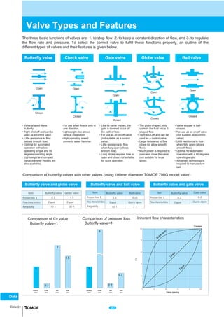
  • 1. Valve Types and Features The three basic functions of valves are: 1. to stop flow, 2. to keep a constant direction of flow, and 3. to regulate the flow rate and pressure. To select the correct valve to fulfill these functions properly, an outline of the different types of valves and their features is given below. Butterfly valve Check valve Gate valve Globe valve Ball valve Open Open Open Open Open Closed Closed Closed Closed Closed Valve shaped like a For use when flow is only in Like its name implies, the The globe-shaped body Valve stopper is ball- butterfly. one direction. gate is lowered to cut off controls the fluid into a S- shaped. Tight shut-off and can be Lightweight disc allows the path of flow. shaped flow. For use as an on/off valve used as a control valve. vertical installation. For use as an on/off valve Tight shut-off and can be (not suitable as a control Little resistance to flow High operating speed (not suitable as a control used as a control valve. valve). (allows smooth flow). prevents water hammer. valve). Large resistance to flow Little resistance to flow Optimal for automated Little resistance to flow (does not allow smooth when fully open (allows operation with a low when fully open (allows flow). smooth flow). operating torque and 90 smooth flow). Much power is required to Optimal for automated degrees operating angle. Long stroke requires time to open and close the valve operation with a 90 degrees Lightweight and compact open and close; not suitable (not suitable for large operating angle. (large diameter models are for quick operation. sizes). Advanced technology is also available). required to manufacture ball. Comparison of butterfly valves with other valves (using 100mm diameter TOMOE 700G model valve) Butterfly valve and globe valve Butterfly valve and ball valve Butterfly valve and gate valve Item Butterfly valve Globe valve Item Butterfly valve Ball valve Item Butterfly valve Gate valve Pressure loss ξ) ( 0.3 1.5 Pressure loss ξ) ( 0.3 0.05 Pressure loss ξ) ( 0.3 0.2 Flow characteristics Equal % Equal % Flow characteristics Equal % Quick open Flow characteristics Equal % Quick open Rangeability : 10 1 : 30 1 Rangeability : 10 1 : 3 1 Comparison of Cv value Comparison of pressure loss Inherent flow characteristics (Butterfly valve=1) (Butterfly valve=1) △P=Constant 100 5 n pe icko Qu 80 2 60 r ea Lin  Cv % 1.5 40 l% ua 1 1 Eq 0.7 20 0.2 0.2 0 0 20 40 60 80 100 Butterfly Globe Ball Gate Butterfly Globe Ball Gate valve valve valve valve valve valve valve valve Valve opening %  Data Data-01 463
  • 2. Valve Sizing Procedures It is essential to understand the valve sizing formula and selection procedure when determining the size of a valve. The following is the proper selection procedure. The valve sizing calculation is based on ISA. 1. Judge if the flow condition is subcritical or critical based on the given flow condition. 2. Calculate the Cv value by putting the data into an appropriate formula. 3. Select the size of the valve using the Cv value chart. Consider the following points when sizing the valve. q A proper adjustment of the Cv calculation should be made based on the piping adjustment coefficient Fp if a valve is located between reducers. w If the result of the Cv calculation is over 80% compared to the full Cv value, select a valve one size larger. Example: For fresh water with P1 = 0.3 MPa, P2 = 0.25 MPa, flow rate = 100 m3/h, the calculated Cv will be 164. If 80 mm, 507V is selected, the rated Cv is 176. The calculated Cv (164) is over 80% of rated the Cv (176) in this case. We recommend 100 mm, 507V. e If no △P is given, 5 to 10% of the pump outlet pressure should be used as the assumed △P for valve sizing. Data 464 Data-02
  • 3. Cv Value Calculation Cv value calculation Data Data-03 465
  • 4. Symbol Legend Symbol Cv: Valve flow coefficient FL: Pressure recovery coefficient G: Specific gravity of gas                    (Air = 1) Gf: Specific gravity at valve-inlet temperature          (Water = 1 at 15 degrees C) P1: Valve-inlet pressure                    (kPaA) P2: Valve-outlet pressure                   (kPaA) △P: Pressure difference across valve [P1 — P2]           (kPa) Pc: Critical pressure                      (kPaA) Pv: Saturated vapour pressure of liquid at valve-inlet temperature (kPaA) △PS: Max. DP for sizing • Working conditions: Outlet pressure is higher than vapour pressure.    △PS = P1 — Pv   (kPa) • Working conditions: Outlet pressure is equal to or lower than vapour pressure. 0.96−0.28 Pv    DPS = P1 —           Pv           (kPa) PC q: Volume flow rate of liquid                  (m3 / h) Q: Volume flow rate of gas [At 15 degrees C, 1 atm]        (m3 / h) 288  = Nm3/h× 273 T: Fluid temperature [273 + degrees C]             (K) Tsh: Degree of superheat                     (degrees C)   = T — Tc Tc: Saturated vapour temperature at valve-inlet pressure (K) W: Mass flow rate (T / h) = (1,000 kg / h) Calculation for piping geometry factor Fp= Fp: Piping geometry factor Cv: Valve flow coefficient d: Valve size (mm) D1: Inlet pipe size (mm) D2: Outlet pipe size (mm) Calculation for modified Cv value CvR = Fp Cv CvR : Revised Cv value Data 466 Data-04
  • 5. Conversion Formula for Reference Pressure loss coefficient Cv value Length of pipe D: Inside diameter of pipe (cm) Q: Flow rate ( /min)        D: Inside diameter of pipe (cm) △P: Pressure difference (kPaA) Cv value Kv value Reference: For performance appraisal of fire safety and disaster prevention Kv value is used in Europe. equipment, the equivalent pipe length is measured based on the flow rates It shows the flow rate (m3/h) of drinking water at a in the table below. pressure of 1 bar and temperature of 5−30 degrees C. Nominal dia. Flow rate(r/min) 50mm 800 65mm 900 80mm 1350 Pressure loss coefficient Kv value 100mm 2100 125mm 3300 150mm 4800 200mm 8500 D: Inside diameter of pipe (cm) 250mm 13000 Cv value Av value 300mm 19000 Av value is a SI unit. Pressure difference   : Pressure loss coefficient △P: Pressure difference (kPa) : Acceleration of gravity 9.8 m/sec2 : Specific gravity (water = 1000) (kg/m3) V: Flow velocity (m/sec) Data Data-05 467
  • 6. Guidance for Vacuum Use Nominal dia. Usable vacuum (kPaA) Valve seat leak Valve type range Remark (mm) 10 to 50 degrees C 50 to 80 degrees C 80 to 100 degrees C (kPa R/h) ・ 80-200 0.133 0.133 1.33 1.0 304A 250-300 1.33 1.33 2.66 8.0 350-600 2.66 3.99 5.32 80-200 1.33 1.33 2.66 8.0 302A 250-300 1.33 3.99 5.32 14.0 350-600 2.66 3.99 5.32 Special gland structure required. 40-200 1.33 1.33 2.66 14.0 302Y 250-300 2.66 3.99 5.32 50-200 1.33 1.33 2.66 14.0 337Y 250-300 2.66 3.99 5.32 40-200 1.33 1.33 2.66 1.0 304Y 250-300 2.66 3.99 5.32 8.0 846T 65-200 Leakage increases if heat cycle 0.133 1.33 2.66 0.3 847T 50-300 and open/close frequency is high. 731P 50-200 0.133 1.33 13.3 0.3 732P 250-300 0.133 2.66 26.6 3.0 731X 350-600 2.66 13.3 Use not possible. 5.0 732X 40-200 13.3 26.6 Use not possible. 3.0 700G 250-300 26.6 53.2 Use not possible. 5.0 350-600 39.9 66.5 Use not possible. 50-200 13.3 26.6 Use not possible. 3.0 705G 704G 250-300 26.6 53.2 Use not possible. 5.0 350-600 39.9 66.5 Use not possible. 125-300 26.6 53.2 Use not possible. 5.0 722F 350-600 39.9 66.5 Use not possible. 250-300 26.6 53.2 Use not possible. 5.0 841T 350-600 39.9 66.5 Use not possible. 842T 350-600 39.9 66.5 Use not possible. Leak amounts are predicted values based on testing at room temperature with new valves. If you will be using in a range that exceeds the above table, please consult us. Data 468 Data-06
  • 7. Velocity Calculation Velocity limitation Velocity limitations are shown below: Type of fluid Velocity limitation (continuous operation) Replaceable rubber seat 3 m/s Liquid Vulcanized rubber seat 5 to 6 m/s Gas, vapour 120 to 200 m/s Saturated steam 50 to 80 m/s Steam Superheated steam 80 to 120 m/s * Velocity limitation varies depending on the valve models. Please consult us for further information. Pipe line velocity calculation For liquids For gases and vapours For steam Where: V: Flow velocity (m/sec) Q: Flow rate Liquid (m3/h) Gas [At 15 degrees C, 101325 Pa] (m3/h) = Nm3/h Steam (kg/h) U: Specific volume of valve-outlet (m3/kg) D: Nominal size (mm) P2: Valve-outlet pressure (kPaA) T: Temperature (degrees C) Data Data-07 469
  • 8. Noise Prediction Methods and Countermeasures Noise measuring method The following are methods recommended by ISA. Note: Parts surrounded by dotted lines are optional. Fig. 1 Laboratory test unit by ISA-RP59.1 Fig. 2 Position of microphone in plant by ISA-RP59.2 Noise calculation formula for 507V and 508V Types Data 470 Data-08
  • 9. Noise calculation formula for valves other than 507V and 508V Types Formulas are in accordance with those introduced by ISA. For gases When liquid cavitation is generated Where: SP: Noise value [sound pressure level at 91cm] (dBA) Cv: Flow coefficient in actual conditions FL: Pressure recovery coefficient P1: Valve upstream pressure (kPaA) P2: Valve downstream pressure (kPaA) m: Weight of pipe wall (kg/m2) η Apparent valve orifice coefficient (butterfly valve: n = 1.4) : TL: Transmission loss → Except for valves releasing directly into the air. *P2crit: P1 — FL2 (P1 — Pv)               (kPaA) Pv: Vapour pressure of liquid               (kPaA) X: Conversion fraction of mechanical output X = 1 even if X is bigger than 1. SG: Gas property factor η: Acoustical efficiency coefficient (Refer to page Data-11.) Note: When the difference between Kc and FL2 exceeds 10% of Kc, substitute Kc for FL2. Data Data-09 471
  • 10. Specific gravity SG Specific gravity SG +2 Saturated steam +1 Superheated steam Natural gas 0 Hydrogen −1 Oxygen Specific gravity SG (dBA) Ammonia −2 Air −3 Acetylene −4 Carbon dioxide Carbon monoxide gas −5 Helium −6 Methane liquid Nitrogen −7 Propane −8 Ethylene −9 Ethane −10 Refer to the graph on left for fluids other than those above. 0 10 20 30 40 50 Molecular weight Weight of pipe (m) m=A×t   *A: Basic weight (kg/mm m2) ・    [Steel pipe: 7.85, stainless steel pipe: 7.93]    t: Pipe thickness (mm) (kg/m2) Nominal dia. m mm inch SGP Sch20 Sch40 Sch60 Sch80 Sch10S Sch20S 40 1 1/2 27.5 − 29.0 35.3 40.0 22.2 23.8 50 2 29.8 25.1 30.6 38.5 43.2 22.2 27.8 65 2 1/2 33.0 35.3 40.8 47.1 55.0 23.8 27.8 80 3 33.0 35.3 43.2 51.8 59.7 23.8 31.7 100 4 35.3 38.5 47.1 55.7 67.5 23.8 31.7 125 5 35.3 40.0 51.8 63.6 74.6 27.0 39.7 150 6 39.3 43.2 55.7 73.0 86.4 27.0 39.7 200 8 45.5 50.2 64.4 80.9 99.7 31.7 51.5 250 10 51.8 50.2 73.0 99.7 118.5 31.7 51.5 300 12 54.2 50.2 80.9 112.3 136.6 35.7 51.5 350 14 62.0 62.0 87.1 118.5 149.2 − − 400 16 62.0 62.0 99.7 131.1 168.0 − − 450 18 62.0 62.0 112.3 149.2 186.8 − − 500 22 62.0 74.6 118.5 161.7 205.7 − − 550 20 − 74.6 124.8 174.3 224.5 − − 600 24 − 74.6 137.4 193.1 243.4 − − Data 472 Data-10
  • 12. Valve noise reduction countermeasures Aerodynamic noise is discussed here. Noise can be reduced at the following points: 1 Noise source 2 Sound insulation When selecting a countermeasure, controllability of process, initial cost and maintenance cost should be considered along with noise evaluation and noise type. Various factors should be discussed between the customer and manufacturer. Please refer to the section Calculation of Estimated Cavitation and its countermeasure to reduce and prevent cavitation noise. Countermeasures for noise source There are two countermeasures for noise source. (1) Adoption of low noise valve q 507V and 508V types: Max. possible reduction is 10 dBA. w Globe type low noise valve: Max. possible reduction is 15 to .30 dBA. (2) Countermeasure at valve downstream side q Insert resistance plate: Max. possible reduction is 15 dBA. Example of low noise unit Sound insulation Example: Pipe lagging materials This countermeasure does not reduce sound generation itself. q Increase of pipe wall thickness (pipe schedule)   If it doubles, 5 dBA can be reduced. w Soundproof lagging   In this countermeasure, piping is covered with layers of     heat insulating materials (rock wool), lead plates, or iron   plates, etc. e Prepare sound insulating box or wall   In order to reduce noise effectively, combine the various   methods mentioned above. Data 474 Data-12
  • 13. Calculation of Estimated Cavitation Cavitation generation in butterfly valves Cavitation is caused by low pressure areas in fluids. There are four causes of low pressure areas: Fig. 1 Butterfly valves in nearly closed position (1) Fluid is compressed, contraction flow exists, and flow velocity is increased. Then, pressure reduces. (2) Low pressure area inside vortexes at valve-outlet side. (3) Low pressure area is produced at the boundary between the fluid flowing at high velocity and objects such as the protruding portion of the valve-moulded surface, heads of taper pins, and hubs, etc. (4) When the valve body or disc is vibrating at high frequency, the flow is disturbed and air bubbles form in the fluid. The main causes of cavitation generation in butterfly valves are (1) and (2). Thus, when the valve is nearly closed, the flow passes over the upper and lower edges of the disc as shown in figure. 1. The low pressure area can be caused when high flow velocity is created. VC (vena cont racta) Fig. 2 Orifice flow Figure 2 shows orifice flow corresponding to valve flow. The contracted part is called vena contracta. The relation between pressure and flow rate is shown in figure 3. VC P1 When fluids flow at high velocity and pressure drops below the saturated vapour pressure, air bubbles are produced. They are carried away toward the valve downstream side, Pressure (P) Flow (V) P2 and then, as surrounding water recovers its original pressure, air bubbles break instantaneously (approx. 1/1000 Pv sec) and produce a strong impact force (200 to 500 atm). If air bubbles break near a substance, the impact applies great stress on both the outside and inside of the Pvc substance, and causes damage to the surface. Fig. 3 Pressure and flow rate relation Data Data-13 475
  • 14. Cavitation generation process in butterfly valves and formula to estimate it There are many stages in cavitation generation, as follows. Flow conditions Pressure conditions Explanation Fig. 4 Normal flow VC P1 P2 Pv Pvc Normal flow means turbulent flow. In this stage, valve flow rate increases in proportion to the square root of the differential pressure. Fig. 5 Cavitation flow Cavitation flow has three stages corre- P1 VC sponding to the increase in differential pressure. a. Incipient cavitation stage P2 b. Critical cavitation stage c. Full cavitation stage Pv Noise and oscillation may cause dam- age to the valve and downstream-side piping. Pvc This occurs when pressure on the valve Fig. 6 Flashing flow downstream side drops below the va- pour pressure of the liquid. The fluid changes from liquid to gas, bringing P1 VC rapid velocity change and volume ex- pansion. These two factors are the main causes of a flashing noise. Flashing noise is of lower level than cavitation noise because gas acts as a Pv cushion. Attention must be paid to materials of P2 the valve body (e.g., upgrading to stain- Pvc less steel or chromium molybdenum steel) or the type of downstream-side piping. Data 476 Data-14
  • 15. Cavitation prediction No cavitation Flashing △P < Kc (P1 — Pv) P2 < Pv FL2 (P1− Pv) > △P Incipient cavitation △P: Pressure difference across valve [P1− P2] (kPa) △P = Kc (P1 — Pv) Kc: Cavitation coefficient P1: Valve-inlet pressure (kPaA) Critical cavitation P2: Valve-outlet pressure (kPaA) Pv: Vapour pressure of liquid (kPaA) FL2 (P1 — Pv) > DP > Kc (P1 — Pv) FL: Pressure recovery coefficient Full cavitation △P ≧ FL2 (P1 — Pv) Cavitation level and availability Type of valve Double “Teflon” Rubber seated offset metal 507V (302A, 304A) (700G, 702Z) 508V Cavitation level 731P No cavitation Suitable Incipient cavitation Consult us regarding usage. Unsuitable Critical cavitation Note: Full cavitation (Countermeasure is necessary) Normal operation material is stainless steel Flashing except when. critical (Countermeasure is necessary) cavitation is determined. Cavitation reduction treatment The following are the main methods for reducing or preventing cavitation damage to control valves. (1) Install valves in series and control them. This method is for reducing the pressure load on each valve. In this case, space valves out at least 4D (4 times the pipe diameter). The total Kc or FL will be improved. In order to avoid full cavitation FL should satisfy the following condition:       FL >   In this case, however, valve control balance may be difficult. Example: When 507V and 508V types are nearly fully opened, FL is 0.72. When 507V and 508V types are installed in series, the combined FL is 0.72 = 0.84 and the permissible pressure difference across the valve is increased by 36%. However, both valves should be operated under exactly the same conditions. (2) Use a resistance plate (perforated orifice for pressure reduction) at the same time. If the flow rate fluctuates heavily, a good result cannot be expected. (3) Use a valve with higher Kc or FL . (4) Lower the installation position of the valve; that is, lower the secondary pressure. However, this method is hard to adopt in existing piping installations. Data (5) Rectify the turbulent flow by using a rectifier grid. Data-15 477
  • 16. Cavitation coefficient Kc and pressure recovery coefficient FL Concentric type butterfly valve 700 and 800 series 1.0 1.0 0.9 0.9 0.8 0.8 0.7 0.7 0.6 0.6 Kc 0.5 FL 0.5 0.4 0.4 0.3 0.3 0.2 0.2 0.1 0.1 0 10 20 30 40 50 60 70 80 90 100 0 10 20 30 40 50 60 70 80 90 100 (Fully closed) Valve opening (%) (Fully open) (Fully closed) Valve opening (%) (Fully open) High performance butterfly valve 300 series 1.0 1.0 0.9 0.9 0.8 0.8 0.7 0.7 0.6 0.6 Kc 0.5 FL 0.5 0.4 0.4 0.3 0.3 0.2 0.2 0.1 0.1 0 10 20 30 40 50 60 70 80 90 100 0 10 20 30 40 50 60 70 80 90 100 (Fully closed) Valve opening (%) (Fully open) (Fully closed) Valve opening (%) (Fully open) Rotary control valve 507V and 508V types 1.0 1.0 0.9 0.9 0.8 0.8 0.7 0.7 0.6 0.6 Kc 0.5 FL 0.5 0.4 0.4 0.3 0.3 0.2 0.2 0.1 0.1 0 10 20 30 40 50 60 70 80 90 100 0 10 20 30 40 50 60 70 80 90 100 (Fully closed) Valve opening (%) (Fully open) (Fully closed) Valve opening (%) (Fully open) Data 478 Data-16
  • 17. Face to Face Dimensions Face to face dimensions Unit: mm Series JIS B 2002 Wafer shape for Wafer shape tandard equipment for ships API594 Reference: Maker’s face-to-face dimension Class125 Diameter 46 47 123 40 33 35 50 43 54 56 40 40 45 45 35 43 65 46 60 56 46 45 45 35 46 80 46 67 60 56 40 50 50 40 64 100 52 67 66 56 40 50 50 40 64 125 56 100 83 70 62 55 55 45 70 150 56 100 95 76 76 52 60 60 50 90 76 200 60 100 127 95 85 62 65 65 60 100 89 250 68 110 140 108 96 89 90 80 110 114 300 78 110 181 144 120 89 90 90 110 114 350 78 92 120 184 89 100 100 120 400 102 102 130 190 108 110 110 130 450 114 114 150 200 120 120 150 500 127 127 160 140 140 160 600 154 154 170 160 160 200 302A・304A 302A・ Tomoe applicable 722F 906C 903C・904C 901C 337Y 507V 841T・842T 700S (discontinued) 700Z 107H・108H 337Y・ (80mm to 300mm) 304A 700E (discontinued) (discontinued) 338Y 302Y・304Y 508V (350mm to (discontinued) types 846T・847T 600mm) 773Z・778Z 700G・704G・705G 731P・732P・ 732X・731X 702Z (discontinued) Remark: For detalied dimensions, please refer to the individual dimensional drawings. Data Data-17 479
  • 18. Unit Conversion Cavitation prediction Pressure unit conversion Temp. conversion table Conversion from pressure unit for Conversion from flow rate unit for each type to K/h each type to MPaA Temperature conversion 3 5 Gas m /h MPa A ℃ = − F−32) (° m3/h 9 (at 15℃ 101kPa) kgf/cm2G ×9.807×10−2+0.1013 9 Gas m3/h − ×Å Bar G −1 ×1×10 +0.1013 ° = − ℃+32 F 5 Gas m3/h Bar A ×1×10 −1 ×ı − ℃ ← ° ℃ F → °F (at 15℃ 101kPa) mmH2O or mmAq ×9.807×10⁻⁶+0.1013 −28.9 −20 −4.5 kg/h ÷SG×0.001 ×23.83÷MW cmH2O or cmAq ×9.807×10⁻⁵+0.1013 −26.1 −15 −5.0 −3 kR/h − ×Å mH2O or mAq ×9.807×10 +0.1013 −23.3 −10 14.0 t/h ÷SG ×1000×23.83÷MW mmHN or Torr ×1.333×10⁻⁴ −20.6 −5 23.0 R/h ×0.001 ÷0.001×Å cmHN ×1.333×10 −3 −17.8 0 32.0 R/min. ×0.06 ×0.06×Å atm ×1.013×10 −1 −15.0 5 41.0 t/min. ÷SG×60 ×60×1000×23.63÷MW atN ×9.807×10⁻²+0.1013 −12.2 10 50.0 −6 Lb/h ×0.4536÷SG×0.001 ×0.4536×23.63÷MW Pa G ×1×10 +0.1013 − 9.4 15 59.0 3 −3 CFH (ft /h) ×0.02832 ×0.02832×Å kPa G ×1×10 +0.1013 3 − 6.7 20 68.0 SCFH (Nft /h) ×0.02832×ı ×0.02832 kPa A ×1×10⁻³ − 3.9 25 77.0 BBL/h (barrel) ×0.159 ×0.159×Å MPa G +0.1013 − 1.1 30 86.0 BBL/min. ×0.159×60 ×0.159×60×Å MPa A      − 1.7 35 95.0 2 GPM (gallon/min.) ×0.2271 ×0.2271×Å Lb/in G (psi G) ×6.895×10⁻³+0.1013 4.4 40 104.0 3 2 CFM (ft /min.) ×1.699 ×1.699×Å Lb/in A(psi A) ×6.895×10⁻³ 7.2 45 113.0 −3 SCFM ×1.699×ı ×1.699 in HN ×3.386×10 10.0 50 122.0 Nm3/h ×T1×0.1013÷ 1×273) ×288÷273 (P 12.8 55 131.0 (at 0℃ 101kPa) 15.6 60 140.0 Å=P1×288÷ 1×0.1013) 1= Valve inlet pressure (T  P (MPaA) 18.3 65 149.0 ı=T1×0.1013÷ 1×288) 1= Temperature K) (P  T (° 21.1 70 158.0 SG = Specific gravity MW= Molecular weight 23.9 75 167.0 26.7 80 176.0 29.4 85 185.0 Pressure conversion table 32.2 90 194.0 Pa kPa MPa bar Of/cm2 atm mH2O mHg Lb/in2 35.0 95 203.0 1 1×10⁻³ 1×10⁻⁶ 1×10⁻⁵ 1.02×10⁻⁵ 9.87×10⁻⁶ 1.02×10⁻⁴ 7.5×10⁻⁶ 1.45×10⁻⁴ 37.8 100 212.0 1×10³ 1 1×10⁻³ 1×10⁻² 1.02×10⁻² 9.87×10⁻³ 1.02×10⁻¹ 7.5×10⁻³ 1.45×10⁻¹ 43.3 110 230.0 1×10⁶ 1×10³ 1 1×10 1.02×10 9.87 1.02×10² 7.5 1.45×10² 48.9 120 248.0 1×10⁵ 1×10² 1×10⁻¹ 1 1.02 9.87×10 -1 1.02×10 7.52×10⁻¹ 1.45×10 54.4 130 266.0 9.81×10⁴ 9.81×10 9.81×10⁻² 9.81×10⁻¹ 1 9.68×10 -1 1×10 7.7×10⁻¹ 1.42×10 60.0 140 284.0 1.01×10⁵ 1.01×10² 1.01×10⁻¹ 1.01 1.03 1 1.03×10 7.6×10⁻¹ 1.47×10 65.6 150 302.0 9.81×10³ 9.81 9.81×10⁻³ 9.81×10⁻² 1×10⁻¹ 9.68×10⁻² 1 7.36×10⁻² 1.42 71.1 160 320.0 1.33×10⁵ 1.33×10² 1.33×10⁻¹ 1.33 1.3 1.32 1.36×10 1 1.93×10 76.7 170 338.0 6.89×10³ 6.89 6.89×10⁻³ 6.89×10⁻² 7.03×10⁻² 6.8×10⁻² 7.03×10⁻¹ 5.17×10⁻² 1 82.2 180 356.0 87.8 190 374.0 93.3 200 392.0 98.9 210 410.0 Torque conversion table Specific gravity conversion 104.4 220 428.0 110.0 230 446.0 oz in ・ Lb in ・ Lb ft ・ O cm ・ O m ・ N cm ・ N m ・ Condition Specific gravity G 121.1 250 482.0 1 0.0625 0.005 0.072 0.0007 0.706 0.007 0 degrees C 148.9 300 572.0 O/Nm3 ÷1.293 16 1 0.083 1.152 0.0115 11.3 0.113 1013mmbar 176.7 350 662.0 192 12 1 13.83 0.138 135.6 1.356 15 degrees C 204.4 400 752.0 O/m3 ÷1.225 13.89 0.868 0.072 1 0.01 9.807 0.098 1013mmbar 232.2 450 842.0 1389 86.8 7.233 100 1 980.7 9.807 260.0 500 932.0 14.16 0.088 0.007 0.102 0.001 1 0.01 315.6 600 1112.0 141.6 8.851 0.738 10.20 0.102 100 1 317.0 700 1292.0 Data 480 Data-18
  • 19. Physical Properties Physical properties of liquids Boiling point Gravity when air Molecular Fluid pressure is 1 Temp. Water weight = 1 at 4° C °C ° F °C ° F Acetaldehyde 20.6 69 20 68 .782 44.05 Acetic acid 118.3 245 20 68 1.049 60.05 Acetone 56.1 133 20 68 .79 58.08 Aero motor oil (typical) −    − 15.6 60 .895 − − − − − − − Alcohol, allyl-n 97.2 207 20 68 .855 58.05 Alcohol, butyl-n 117.2 243 20 68 .81 74.12 117.2 243 70 158 .78   − Alcohol, ethyl-n (grain) 77.8 172 20 68 .789 46.07 Alcohol, methy-n (wood) 66.1 151 20 68 .79 102.17 Alcohol, propyl-n 97.2 207 − 17.8 0 .804 60.09 Ammonia (liquid) − 33.3 − 28 20 68 .662 17.31 Aniline 183.9 363 20 68 1.022 93.12 Automobile crankcase oils, SAE 10   −   − 15.6 60 .88 — .94   − SAE 20   −   − 15.6 60 .88 — .94   − SAE 30   −   − 15.6 60 .88 — .94   − SAE 40   −   − 15.6 60 .88 — .94   − SAE 50   −   − 15.6 60 .88 — .94   − SAE 60   −   − 15.6 60 .88 — .94   − SAE 70   −   − 15.6 60 .88 — .94   − Automobile transmission lub, SAE 80   −   − 15.6 60 .88 — .94   − SAE 90   −   − 15.6 60 .88 — .94   − SAE 140   −   − 15.6 60 .88 — .94   − SAE 250   −   − 15.6 60 .88 — .94   − Beer   −   − 15.6 60 1.01   − Benzol (Benzene) 80 176 20 68 .879 78.11 Brine, calcium chloride, 25%   −   − 15.6 60 1.23 − Brine, sodium chloride, 25%   −   − 15.6 60 1.19 − Bromine 61.1 142 20 68 2.9 159.83 Butyric acid-n 157.8 316 20 68 .959 88.10 Carbolic acid (phenol) 182.2 360 18.3 65 1.08 94.11 Carbon disulphide 46.1 115 20 68 1.263 76.14 Carbon tetrachloride 76.7 170 20 68 1.594 153.84 Castor oil   −   − 20 68 .96 − Chloroform 61.1 142 20 68 1.489 119.39 Compounded steam cyl oil (5% tal, ow)   −   − 15.6 60 .90 −   −   − − − − − Decane-n 172.8 343 20 68 .73 142.28 Diethyl ether 34.7 94.4 20 68 .714 74.12 Ethyl acetate 77.2 171 20 68 .90 88.10 Ethyl biomide 38.3 101 15 59 1.45 108.98 Ethylene btomide 131.7 269 20 68 2.18 187.88 Ethylene chloride 83.9 183 20 68 1.246 98.97 Formic acid 100.6 213 20 68 1.221 46.03 Data Data-19 481
  • 20. Physical properties of liquids Boiling point Gravity when air Molecular Fluid pressure is 1 Temp. Water weight = 1 at 4° C ° C ° F °C ° F Freon 11 − − 21.1 70 1.49 − Freon 12 − − 26.1 79 1.33 − Freon 21 − − 21.1 70 1.37 − Fuel oil, No.1 − − 15.6 60 .82 — .95 − No.2 − − 15.6 60 .82 — .95 − No.3 − − 15.6 60 .82 — .95 − No.5 − − 15.6 60 .82 — .95 − No.6 − − 15.6 60 .82 — .95 − Gasoline, typical (a) − − — 14.4 6 .74 − (b) − − — 14.4 6 .72 − (c) − − — 14.4 6 .68 − Glycerine, 100% 290 554 20 68 1.26 92.03 Glycerine and water. 50% − − 20 68 1.13 − Glycol, Ethylene − − 20 68 1.125 62.07 Heptane-n 98.3 209 20 68 .684 100.20 Hexane-n 68.9 156 20 68 .66 86.17 Hydrochloric acid, 31.5% − − 20 68 1.05 − Kerosene − − 15.6 60 .78 — .82 − Lard oil − − 15.6 60 .91 — .92 − Linseed oil (raw) 28.1 538 15.6 60 .92 — .94 − Marine engine oil (20% blown rape) − − 15.6 60 .94 − Methy acetate 57.2 135 20 68 .93 58.08 Methy iodide 42.2 108 20 68 2.28 141.94 Milk − − 20 68 1.02 — 1.04 − Naphthelene 217.8 424 20 68 1.145 − Neatsfoot oil − − 15.6 60 .91 — .92 − Nitric acid, 60% − − 20 68 1.37 − Nitrobenzene 211.1 412 20 68 1.203 − Nonane-n 150 302 20 68 .718 128.6 Octane-n 125.6 258 20 68 .70 − Olive oil (298.9) (570) 20 68 .91 − Pentane-n 36.1 97 20 68 .63 123.11 Petroleum ether (benzine) − − 15.6 60 .64 128.25 Propionic acid 141.1 286 20 68 .99 114.22 Quenching oil (typical) − − 15.6 60 .86 — .89 − Rapeseed oil − − 20 68 .91 72.09 Soya bean oil − − 15.6 60 .924 − Sperm oil (98.3) (209) 25 77 .88 74.08 Sugar, 20% − − 20 68 1.08 − 40% − − 20 68 1.18 − 60% − − 20 68 1.29 − Sulfuric acid, 100% 337.8 640 20 68 1.83 98.08 95%  − − 20 68 1.83 − 60%  − − 20 68 1.50 − Turbine oil (typical medium)  − − 15.6 60 .91 − Turpentine 160 320 15.6 60 .86 — .87 136.23 Water (fresh) 100 212 15.6 60 1.0 − Water (sea)  − − 15.6 60 1.03 − Xyolene-o 141.7 287 20 68 .87 − Data 482 Data-20
  • 21. Density of fluids Density Density Temp. Fluid g° 3 /cm ° C Acetone 0.792 49.4 20 Alcohol, ethyl 0.791 49.4 20 Alcohol, methyl 0.810 50.5 0 Benzene 0.899 56.1 0 Carbolic acid 0.950 — 0.965 59.2 — 60.2 15 Carbon disulfide 1.293 80.7 0 Carbon tetrachloride 1.595 99.6 20 Chloroform 1.489 93.0 20 Ether 0.736 45.9 0 Gasoline 0.66 — 0.69 41.0 — 43.0 − Glycerin 1.260 78.6 0 Kerosene 0.82 51.2 − Mercury 13.6 849.0 − Milk 1.028 — 1.035 64.2 — 64.6 − Naphtha, petroleum ether 0.665 41.5 15 Wood 0.848 — 0.810 52.9 — 50.5 0 Oils: Castor 0.969 60.5 15 Coconut 0.925 57.7 15 Cotton seed 0.926 57.8 16 Creosote 1.040 — 1.100 64.9 — 68.6 15 Linseed, boiled 0.942 58.8 15 Olive 0.918 57.3 15 Sea water 1.025 63.99 15 Turpentine (spirits) 0.87 54.3 − Water 1.00 62.43 4 Data Data-21 483
  • 22. Critical pressures and temperatures Critical pressure Pc Critical temperature Tc Fluid kPaA Bars (abs.) ° F ° C Acetic acid 5798 58.0 612 322 Acetone 4764 47.6 455 235 Acetylene 6280 62.9 97 36 Air 3771 37.8 − 222 − 141 Ammonia 11297 113.0 270 132 Argon 4860 48.6 − 188 − 122 Benzene 4833 48.4 552 289 Butane 3647 36.5 307 153 Carbon dioxide 7390 74.0 88 31 Carbon monoxide 3543 35.5 − 218 − 139 Carbon tetrachloride 4557 45.6 541 283 Chlorine 7708 77.0 291 144 Ethane 4944 49.5 90 32 Ethyl alcohol 6391 64.0 469 243 Ethylene 5115 51.2 50 10 Ethyl ether 3599 36.0 383 195 Fluorine 2530 25.3 − 247 − 155 Helium 228.9 2.29 − 450 − 268 Heptane 2716 27.2 513 267 Hydrogen 1296 13.0 − 400 − 240 Hydrogen chloride 8266 82.6 124 51 Isobutane 3750 37.5 273 134 Isopropyl alcohol 5370 53.7 455 235 Methane 4640 46.4 − 117 − 83 Methyl alcohol 7970 79.6 464 240 Nitrogen 3392 34.0 − 233 − 147 Nitrous oxide 7267 72.7 99 37 Octane 2496 25.0 565 296 Oxygen 5033 50.4 − 182 − 119 Pentane 3344 33.5 387 197 Phenol 6129 61.3 786 419 Phosgene 5674 56.7 360 182 Propane 4254 42.6 207 97 Propylene 4557 45.6 198 92 Refrigerant 12 4012 40.1 234 112 Refrigerant 22 4915 49.2 207 97 Sulfur dioxide 7873 78.8 315 157 Water 22104 221.0 705 374 Data Data-22 484
  • 23. Physical properties of gases Density Gravity Gravity Molecular Fluid kg m—3 ・ weight Air = 1 Oxygen = 1 (0° 101325 Pa) C, Acetylene 1.173 0.9073 0.8208 26.04 Air 1.2929 1.0000 .9047 28.97 Ammonia .7710 .5963 .5395 17.03 Argon 1.7837 1.3796 1.2482 39.944 Arsenic fluoride 7.71* 5.96* 5.40* 169.91 Arsenic hydride 3.484* 2.695* 2.438* 76.93 Boron fluoride 2.99* 2.31* 2.09* 61.82 Butane (n) 2.5190* 2.0854* 1.8868* 58.12 Butane, iso 2.673 2.067 1.870 58.12 Carbon dioxide 1.9769 1.5290 1.3834 44.01 Carbon monoxide 1.2504 .9671 .8750 28.01 Carbon oxysulfide 2.72 2.10 1.90 60.07 Chlorine 3.214 2.486 2.249 70.91 Chlorine dioxide 3.0911 2.3911 2.1611 67.46 Chlorine monoxide 3.89 3.01 2.72 86.91 Cyanogen 2.335* 1.806 1.634* 52.04 Dimethylamine 1.96617 1.52117 1.37617 45.08 Ethane 1.3566 1.0493 .9493 30.07 Ethylene 1.2604 .9749 .8820 28.05 Fluorine 1.696 1.312 1.187 38.00 Germanium hydride (digermane) 6.7420 5.2120 4.7220 151.25 Germanium tetrahydride 3.420 2.645 2.393 76.63 Helium .17847 .13804 .12489 4.003 Hydrogen .08988 .06952 .06290 2.016 Hydrogen bromide 3.6445 2.8189 2.5503 80.92 Hydrogen chloride 1.6392 1.2678 1.1471 36.47 Hydrogen iodide 5.7891 4.4776 4.0510 127.93 Hydrogen selenide 3.670 2.839 2.568 80.98 Hydrogen sulfide 1.539 1.190 1.077 34.08 Hydrogen telluride 5.81 4.49 4.07 129.63 Krypton 3.708 2.868 2.595 83.70 Methane .7168 .5544 .5016 16.04 Methylamine 1.396 1.080 .9769 31.06 Methyl chloride 2.3076 1.7848 1.6148 50.49 Methyl ether 2.1098 1.6318 1.4764 46.07 Methyl fluoride 1.5452 1.1951 1.0813 34.03 Neon .90036 .69638 .63004 20.18 Data Nitric oxide 1.3402 1.0366 .9378 30.01 Data-23 485
  • 24. Physical properties of gases Density Gravity Gravity Molecular Fluid kg m—3 ・ weight Air = 1 Oxygen = 1 (0° 101325 Pa) C, Nitrogen 1.25055 .96724 .87510 28.02 Nitrogen (atm.) 1.2568 .9721 .8795   − Nitrosyl chloride 2.992 2.314 2.094 65.47 Nitrosyl fluoride 2.176* 1.683* 1.523* 49.01 Nitrous oxide 1.9778 1.5297 1.3840 44.02 Nitroxyl chloride 2.57* 1.99* 1.798* 81.47 Nitroxyl fluoride 2.90 2.24 2.03 65.01 Oxygen 1.42904 1.10527 1.0000 32.00 Ozone 2.144 1.658 1.500 48.00 Phosphine 1.5294 1.1829 1.0702 34.00 Phosphorus fluoride 3.907* 3.022* 2.734* 87.98 Phosphorus oxyfluoride 4.8 3.7 3.4 103.98 Phosphorus pentafluoride 5.81 4.494 4.066 125.98 Propane 2.0096 1.554 1.407 44.09 Radon 9.73 7.526 6.809 222.00 Silicane, chloro- 3.03 2.34 2.12 66.54 Silicane, chloromethyl 3.64 2.82 2.55 80.60 Silicane, dichloromethyl 5.3 4.1 3.7 115.02 Silicane, dimethyl 2.73 2.11 1.91 60.14 Silicane, methyl 2.08 1.61 1.46 46.12 Silicane, trifluoro- 3.86 2.99 2.70 86.07 Silicon fluoride 4.684 3.623 3.278 104.06 Silicon hexahydride 2.85 2.204 1.994 62.17 Silicon tetrahydride 1.44 1.114 1.008 32.09 Stibine (15° 754A) C, 5.30 4.10 3.71 125.00 Sulfur dioxide 2.9269 2.2638 2.0482 64.07 Sulfur fluoride 6.50* 5.03* 4.55* 146.07 Sulfuric oxyfluoride 3.72* 2.88* 2.60* 102.07 Trimethylamine 2.580 1.996 1.085 59.11 Trimethyl boron 2.52 1.95 1.76 55.92 Tungsten fluoride 12.9 9.98 9.03 297.92 Xenon 5.851 4.525 4.094 131.30 * Density at 20° C. Data 486 Data-24