

Recomendados
Mais conteúdo relacionado
Destaque
Destaque (20)
Inverter circuit diagram
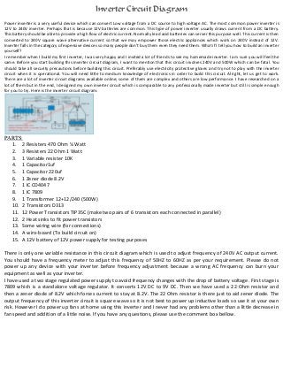
- 1. Inverter Circuit Diagram Power inverter is a very useful device which can convert Low voltage from a DC source to high voltage AC. The most common power inverter is 12V to 240V inverter. Perhaps that is because 12V batteries are common. This type of power inverter usually draws current from a DC battery. This battery should be able to provide a high flow of electric current. Normally lead acid batteries can server this purpose well. This current is then converted to 240V square wave alternative current so that we may empower those electric appliances which work on 240V instead of 12V. Inverter falls in the category of expensive devices so many people don’t buy them even they need them. What if I tell you how to build an inverter yourself? I remember when I build my first inverter, I was very happy and I invited a lot of friends to see my homemade inverter. I am sure you will feel the same. Before you start building this inverter circuit diagram, I want to mention that this circuit involves 240V and 500W which can be fatal. You should take all security precautions before building this circuit. Preferably use electricity protective gloves and try not to play with the inverter circuit when it is operational. You will need little to medium knowledge of electronics in order to build this circuit. Alright, let us get to work. There are a lot of inverter circuit diagrams available online; some of them are complex and others are low performance. I have researched on a lot of them but in the end, I designed my own inverter circuit which is comparable to any professionally made inverter but still is simple enough for you to try. Here is the inverter circuit diagram: PARTS: 1. 2 Resisters 470 Ohm ¼ Watt 2. 3 Resisters 22 Ohm 1 Watt 3. 1 Variable resister 10K 4. 1 Capacitor1uf 5. 1 Capacitor 220uf 6. 1 Zener diode 8.2V 7. 1 IC CD4047 8. 1 IC 7809 9. 1 Transformer 12+12/240 (500W) 10. 2 Transistors D313 11. 12 Power Transistors TIP35C (make two pairs of 6 transistors each connected in parallel) 12. 2 Heat sinks to fit power transistors 13. Some wiring wire (for connections) 14. A wiro-board (To build circuit on) 15. A 12V battery of 12V power supply for testing purposes There is only one variable resistance in this circuit diagram which is used to adjust frequency of 240V AC output current. You should have a frequency meter to adjust this frequency of 50HZ to 60HZ as per your requirement. Please do not power up any device with your inverter before frequency adjustment because a wrong AC frequency can burn your equipment as well as your inverter. I have used a two stage regulated power supply to avoid frequency changes with the drop of battery voltage. First stage is 7809 which is a standalone voltage regulator. It converts 12V DC to 9V DC. Then we have used a 22 Ohm resistor and then a zener diode of 8.2V which forces current to stay at 8.2V. The 22 Ohm resistor is there just to aid zener diode. The output frequency of this inverter circuit is square wave so it is not best to power up inductive loads so use it at your own risk. However I do power up fans at home using this inverter and I never had any problems other than a little decrease in fan speed and addition of a little noise. If you have any questions, please use the comment box bellow.