Lm317
- 1. KA317/LM317—3-TerminalPositiveAdjustableRegulator
© 2002 Fairchild Semiconductor Corporation www.fairchildsemi.com
KA317 / LM317 Rev. 1.2.1 1
July 2013
KA317 / LM317
3-Terminal Positive Adjustable Regulator
Features
• Output-Current In Excess of 1.5 A
• Output-Adjustable Between 1.2 V and 37 V
• Internal Thermal Overload Protection
• Internal Short-Circuit Current Limiting
• Output-Transistor Safe Operating Area Compensation
• TO-220 Package
Ordering Information
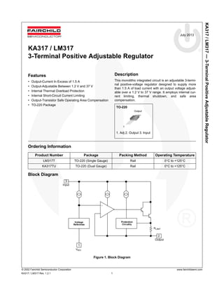
Block Diagram
Figure 1. Block Diagram
Product Number Package Packing Method Operating Temperature
LM317T TO-220 (Single Gauge) Rail 0°C to +125°C
KA317TU TO-220 (Dual Gauge) Rail 0°C to +125°C
Rlimit
3Vin
Vo
1
Voltage
Reference
Vadj
2
Protection
Circuitry
+
-
Input
Output
AdjVADJ
RLIMIT
Description
This monolithic integrated circuit is an adjustable 3-termi-
nal positive-voltage regulator designed to supply more
than 1.5 A of load current with an output voltage adjust-
able over a 1.2 V to 37 V range. It employs internal cur-
rent limiting, thermal shutdown, and safe area
compensation.
TO-220
1. Adj 2. Output 3. Input
1
Output
- 2. KA317/LM317—3-TerminalPositiveAdjustableRegulator
© 2002 Fairchild Semiconductor Corporation www.fairchildsemi.com
KA317 / LM317 Rev. 1.2.1 2
Absolute Maximum Ratings
Stresses exceeding the absolute maximum ratings may damage the device. The device may not function or be opera-
ble above the recommended operating conditions and stressing the parts to these levels is not recommended. In addi-
tion, extended exposure to stresses above the recommended operating conditions may affect device reliability. The
absolute maximum ratings are stress ratings only. Values are at TA = 25°C unless otherwise noted.
Thermal Characteristics
Symbol Parameter Value Unit
VI - VO Input-Output Voltage Differential 40 V
TLEAD Lead Temperature 230 °C
TJ Operating Junction Temperature Range 0 to +125 °C
TSTG Storage Temperature Range -65 to +125 °C
ΔVO/ΔT Temperature Coefficient of Output Voltage ±0.02 %/°C
Symbol Parameter Value Units
PD Power Dissipation Internally Limited W
RθJA Thermal Resistance, Junction to Ambient 80 °C/W
RθJC Thermal Resistance, Junction to Case 5 °C/W
- 3. KA317/LM317—3-TerminalPositiveAdjustableRegulator
© 2002 Fairchild Semiconductor Corporation www.fairchildsemi.com
KA317 / LM317 Rev. 1.2.1 3
Electrical Characteristics
VI-VO = 5 V, IO = 0.5 A, 0°C ≤ TJ ≤ +125°C, IMAX = 1.5 A, PDMAX = 20 W, unless otherwise specified.
Notes:
1. Load and line regulation are specified at constant junction temperature. Change in VD due to heating effects must be
taken into account separately. Pulse testing with low duty is used (PMAX = 20 W).
2. CADJ, when used, is connected between the adjustment pin and ground.
Symbol Parameter Conditions Min. Typ. Max. Unit
RLINE Line Regulation(1)
TA = +25°C, 3 V ≤ VI - VO ≤ 40 V 0.01 0.04 %/ V
3 V ≤ VI - VO ≤ 40 V 0.02 0.07 %/ V
RLOAD Load Regulation(1)
TA = +25°C,
10mA ≤ IO ≤ IMAX
VO < 5 V 18 25 mV
VO ≥ 5 V 0.4 0.5 %/VO
10 mA ≤ IO ≤ IMAX
VO < 5 V 40 70 mV
VO ≥ 5 V 0.8 1.5 %/VO
IADJ Adjustable Pin Current 46 100 μA
ΔIADJ
Adjustable Pin Current
Change
3 V ≤ VI - VO ≤ 40 V,
10 mA ≤ IO ≤ IMAX, PD ≤ PMAX
2.0 5.0 μA
VREF Reference Voltage
3 V ≤ VIN - VO ≤ 40 V,
10 mA ≤ IO ≤ IMAX, PD ≤ PMAX
1.20 1.25 1.30 V
STT Temperature Stability 0.7 %/VO
IL(MIN)
Minimum Load Current
to Maintain Regulation
VI - VO = 40 V 3.5 12.0 mA
IO(MAX)
Maximum Output
Current
TA = 25°C
VI - VO ≤ 15 V,
PD ≤ PMAX
1.5 2.2 A
VI - VO ≤ 40 V,
PD ≤ PMAX
0.3 A
eN RMS Noise,% of VOUT TA = +25°C, 10 Hz ≤ f ≤ 10 kHz 0.003 0.010 %/VO
RR Ripple Rejection
VO = 10 V, f = 120 Hz without CADJ 60 dB
CADJ = 10 μF(2)
66 75 dB
ST
Long-Term Stability, TJ =
THIGH
TA = +25°C for End Point
Measurements, 1000 HR
0.3 1.0 %
- 4. KA317/LM317—3-TerminalPositiveAdjustableRegulator
© 2002 Fairchild Semiconductor Corporation www.fairchildsemi.com
KA317 / LM317 Rev. 1.2.1 4
Typical Performance Characteristics
Figure 2. Load Regulation Figure 3. Adjustment Current
Figure 4. Dropout Voltage Figure 5. Reference Voltage
Figure 6. Short Circuit vs. Input-Output Voltage
TEMPERATURE (°C)
OUTPUTVOLTAGEDEVIATION(%)
TEMPERATURE (°C)
ADJUSTMENTCURRENT(uA)
TEMPERATURE (°C)
INPUT-OUTPUTDIFFERENTIAL(V)
TEMPERATURE (°C)
REFERENCEVOLTAGE(V)
0 5 10 15 20 25 30 35 40
0
1
2
3
ISC
-SHORTCIRCUITCURRENT(A)
VI
-VO
- INPUT OUTPUT VOLTAGE [V]
TA
= 25
o
C
VOUT
= 1.25 V, Shorthed to GND
- 5. KA317/LM317—3-TerminalPositiveAdjustableRegulator
© 2002 Fairchild Semiconductor Corporation www.fairchildsemi.com
KA317 / LM317 Rev. 1.2.1 5
Typical Application(3)
Figure 7. Typical Application
Note:
3. CI is required when the regulator is located an appreciable distance from power supply filter. CO is not needed for
stability; however, it does improve transient response. Since IADJ is controlled to less than 100 μA, the error
associated with this term is negligible in most applications.
VI
VO
VADJ
OutputInput
R2
Co
1 μF
Ci
0.1 μF
adj
IADJ
VO = 1.25 V (1 + R2 / R1) + IADJR2
R1
240 Ω
KA317 / LM317
- 6. KA317/LM317—3-TerminalPositiveAdjustableRegulator
© 2002 Fairchild Semiconductor Corporation www.fairchildsemi.com
KA317 / LM317 Rev. 1.2.1 6
Physical Dimensions
Figure 8. TO-220, MOLDED, 3-LEAD, JEDEC, VARIATION AB
Package drawings are provided as a service to customers considering Fairchild components. Drawings may change in any manner
without notice. Please note the revision and/or date on the drawing and contact a Fairchild Semiconductor representative to verify or
obtain the most recent revision. Package specifications do not expand the terms of Fairchild’s worldwide terms and conditions, specifically the
warranty therein, which covers Fairchild products.
Always visit Fairchild Semiconductor’s online packaging area for the most recent package drawings:
http://www.fairchildsemi.com/dwg/TO/TO220B03.pdf.
For current tape and reel specifications, visit Fairchild Semiconductor’s online packaging area:
http://www.fairchildsemi.com/packing_dwg/PKG-TO220B03.pdf.
TO-220 [ SINGLE GAUGE ]
- 7. KA317/LM317—3-TerminalPositiveAdjustableRegulator
© 2002 Fairchild Semiconductor Corporation www.fairchildsemi.com
KA317 / LM317 Rev. 1.2.1 7
Physical Dimensions (continued)
Figure 9. TO220, MOLDED, 3-LEAD, NON-JEDEC, VARIATION AB
Package drawings are provided as a service to customers considering Fairchild components. Drawings may change in any manner
without notice. Please note the revision and/or date on the drawing and contact a Fairchild Semiconductor representative to verify or
obtain the most recent revision. Package specifications do not expand the terms of Fairchild’s worldwide terms and conditions, specifically the
warranty therein, which covers Fairchild products.
Always visit Fairchild Semiconductor’s online packaging area for the most recent package drawings:
http://www.fairchildsemi.com/dwg/TO/TO220Y03.pdf.
For current tape and reel specifications, visit Fairchild Semiconductor’s online packaging area:
http://www.fairchildsemi.com/packing_dwg/PKG-TO220Y03.pdf.
TO-220 [ DUAL GAUGE ]
- 8. © Fairchild Semiconductor Corporation www.fairchildsemi.com
TRADEMARKS
The following includes registered and unregistered trademarks and service marks, owned by Fairchild Semiconductor and/or its global subsidiaries, and is not
intended to be an exhaustive list of all such trademarks.
2Cool
AccuPower
AX-CAP®
*
BitSiC
Build it Now
CorePLUS
CorePOWER
CROSSVOLT
CTL
Current Transfer Logic
DEUXPEED®
Dual Cool™
EcoSPARK®
EfficientMax
ESBC
Fairchild®
Fairchild Semiconductor®
FACT Quiet Series
FACT®
FAST®
FastvCore
FETBench
FPS
F-PFS
FRFET®
Global Power Resource
SM
GreenBridge
Green FPS
Green FPS e-Series
Gmax
GTO
IntelliMAX
ISOPLANAR
Making Small Speakers Sound Louder
and Better™
MegaBuck
MICROCOUPLER
MicroFET
MicroPak
MicroPak2
MillerDrive
MotionMax
mWSaver
OptoHiT
OPTOLOGIC®
OPTOPLANAR®
®
PowerTrench®
PowerXS™
Programmable Active Droop
QFET®
QS
Quiet Series
RapidConfigure
Saving our world, 1mW/W/kW at a time™
SignalWise
SmartMax
SMART START
Solutions for Your Success
SPM®
STEALTH
SuperFET®
SuperSOT -3
SuperSOT -6
SuperSOT -8
SupreMOS®
SyncFET
Sync-Lock™
®*
TinyBoost
TinyBuck
TinyCalc
TinyLogic®
TINYOPTO
TinyPower
TinyPWM
TinyWire
TranSiC
TriFault Detect
TRUECURRENT®
*
SerDes
UHC®
Ultra FRFET
UniFET
VCX
VisualMax
VoltagePlus
XS™
* Trademarks of System General Corporation, used under license by Fairchild Semiconductor.
DISCLAIMER
FAIRCHILD SEMICONDUCTOR RESERVES THE RIGHT TO MAKE CHANGES WITHOUT FURTHER NOTICE TO ANY PRODUCTS HEREIN TO IMPROVE
RELIABILITY, FUNCTION, OR DESIGN. FAIRCHILD DOES NOT ASSUME ANY LIABILITY ARISING OUT OF THE APPLICATION OR USE OF ANY PRODUCT
OR CIRCUIT DESCRIBED HEREIN; NEITHER DOES IT CONVEY ANY LICENSE UNDER ITS PATENT RIGHTS, NOR THE RIGHTS OF OTHERS. THESE
SPECIFICATIONS DO NOT EXPAND THE TERMS OF FAIRCHILD’S WORLDWIDE TERMS AND CONDITIONS, SPECIFICALLY THE WARRANTY THEREIN,
WHICH COVERS THESE PRODUCTS.
LIFE SUPPORT POLICY
FAIRCHILD’S PRODUCTS ARE NOT AUTHORIZED FOR USE AS CRITICAL COMPONENTS IN LIFE SUPPORT DEVICES OR SYSTEMS WITHOUT THE
EXPRESS WRITTEN APPROVAL OF FAIRCHILD SEMICONDUCTOR CORPORATION.
As used herein:
1. Life support devices or systems are devices or systems which, (a) are
intended for surgical implant into the body or (b) support or sustain
life, and (c) whose failure to perform when properly used in
accordance with instructions for use provided in the labeling, can be
reasonably expected to result in a significant injury of the user.
2. A critical component in any component of a life support, device, or
system whose failure to perform can be reasonably expected to
cause the failure of the life support device or system, or to affect its
safety or effectiveness.
ANTI-COUNTERFEITING POLICY
Fairchild Semiconductor Corporation's Anti-Counterfeiting Policy. Fairchild's Anti-Counterfeiting Policy is also stated on our external website, www.fairchildsemi.com,
under Sales Support.
Counterfeiting of semiconductor parts is a growing problem in the industry. All manufacturers of semiconductor products are experiencing counterfeiting of their
parts. Customers who inadvertently purchase counterfeit parts experience many problems such as loss of brand reputation, substandard performance, failed
applications, and increased cost of production and manufacturing delays. Fairchild is taking strong measures to protect ourselves and our customers from the
proliferation of counterfeit parts. Fairchild strongly encourages customers to purchase Fairchild parts either directly from Fairchild or from Authorized Fairchild
Distributors who are listed by country on our web page cited above. Products customers buy either from Fairchild directly or from Authorized Fairchild Distributors
are genuine parts, have full traceability, meet Fairchild's quality standards for handling and storage and provide access to Fairchild's full range of up-to-date technical
and product information. Fairchild and our Authorized Distributors will stand behind all warranties and will appropriately address any warranty issues that may arise.
Fairchild will not provide any warranty coverage or other assistance for parts bought from Unauthorized Sources. Fairchild is committed to combat this global
problem and encourage our customers to do their part in stopping this practice by buying direct or from authorized distributors.
PRODUCT STATUS DEFINITIONS
Definition of Terms
Datasheet Identification Product Status Definition
Advance Information Formative / In Design
Datasheet contains the design specifications for product development. Specifications may change
in any manner without notice.
Preliminary First Production
Datasheet contains preliminary data; supplementary data will be published at a later date. Fairchild
Semiconductor reserves the right to make changes at any time without notice to improve design.
No Identification Needed Full Production
Datasheet contains final specifications. Fairchild Semiconductor reserves the right to make
changes at any time without notice to improve the design.
Obsolete Not In Production
Datasheet contains specifications on a product that is discontinued by Fairchild Semiconductor.
The datasheet is for reference information only.
Rev. I64
®