RETAINING WALL ANALYSIS
•
2 gostaram•767 visualizações

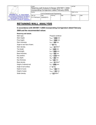
This document provides details of a proposed retaining wall, including dimensions, material properties, and calculations of forces and moments acting on the wall according to Eurocode 7. Key details include a propped cantilever retaining wall with a stem height of 5.5m, retaining loose gravel soil up to 5m high. Calculations show total vertical and horizontal forces of 778.7kN/m and 339.2kN/m respectively. The maximum bearing pressure on the wall foundation is calculated to be 0kPa with no eccentricity of loading.

Recomendados
Recomendados
Mais conteúdo relacionado
Mais procurados
Mais procurados (20)
Semelhante a RETAINING WALL ANALYSIS
Semelhante a RETAINING WALL ANALYSIS (17)
Mais de Dr.Costas Sachpazis
Mais de Dr.Costas Sachpazis (20)
Último
Último (20)
RETAINING WALL ANALYSIS
- 1. Project Job Ref. Retaining wall Analysis & Design (EN1997-1:2004 incorporating Corrigendum dated February 2009) Section GEODOMISI Ltd. - Dr. Costas Sachpazis Civil & Geotechnical Engineering Consulting Company for Structural Engineering, Soil Mechanics, Rock Mechanics, Foundation Engineering & Retaining Structures. Sheet no./rev. Civil & Geotechnical Engineering Calc. by Date Dr.C.Sachpazis 23/05/2013 Chk'd by Date 1 App'd by Date - Tel.: (+30) 210 5238127, 210 5711263 - Fax.:+30 210 5711461 Mobile: (+30) 6936425722 & (+44) 7585939944, costas@sachpazis.info RETAINING WALL ANALYSIS In accordance with EN1997-1:2004 incorporating Corrigendum dated February 2009 and the recommended values Retaining wall details Stem type; Stem height; Propped cantilever hstem = 5500 mm Prop height; hprop = 4500 mm Stem thickness; tstem = 500 mm Angle to rear face of stem; α = 90 deg Stem density; γstem = 25 kN/m Toe length; ltoe = 1000 mm Heel length; lheel = 3000 mm Base thickness; tbase = 500 mm Key position; pkey = 4150 mm Key depth; dkey = 500 mm Key thickness; tkey = 350 mm Base density; γbase = 25 kN/m Height of retained soil; 3 hret = 5000 mm 3 Angle of soil surface; β = 0 deg Depth of cover; dcover = 500 mm Height of water; hwater = 150 mm Water density; γw = 9.8 kN/m 3
- 2. Project Job Ref. Retaining wall Analysis & Design (EN1997-1:2004 incorporating Corrigendum dated February 2009) Section GEODOMISI Ltd. - Dr. Costas Sachpazis Civil & Geotechnical Engineering Consulting Company for Structural Engineering, Soil Mechanics, Rock Mechanics, Foundation Engineering & Retaining Structures. Sheet no./rev. Civil & Geotechnical Engineering Calc. by Date Dr.C.Sachpazis 23/05/2013 Chk'd by Date - Tel.: (+30) 210 5238127, 210 5711263 - Fax.:+30 210 5711461 Mobile: (+30) 6936425722 & (+44) 7585939944, costas@sachpazis.info Retained soil properties Soil type; Very loose gravel Moist density; γmr = 16 kN/m Saturated density; γsr = 20 kN/m 3 3 1 App'd by Date
- 3. Project Job Ref. Retaining wall Analysis & Design (EN1997-1:2004 incorporating Corrigendum dated February 2009) Section GEODOMISI Ltd. - Dr. Costas Sachpazis Civil & Geotechnical Engineering Consulting Company for Structural Engineering, Soil Mechanics, Rock Mechanics, Foundation Engineering & Retaining Structures. Sheet no./rev. Civil & Geotechnical Engineering Calc. by Date Dr.C.Sachpazis 23/05/2013 Chk'd by 1 Date App'd by Date - Tel.: (+30) 210 5238127, 210 5711263 - Fax.:+30 210 5711461 Mobile: (+30) 6936425722 & (+44) 7585939944, costas@sachpazis.info Characteristic effective shear resistance angle; φ'r.k = 26 deg Characteristic wall friction angle; δr.k = 13 deg Base soil properties Soil type; Firm clay Moist density; γmb = 18 kN/m Characteristic cohesion; c'b.k = 25 kN/m Characteristic adhesion; ab.k = 20 kN/m Characteristic effective shear resistance angle; 2 δb.k = 9 deg Characteristic base friction angle; 2 φ'b.k = 18 deg Characteristic wall friction angle; 3 δbb.k = 12 deg Loading details Variable surcharge load; SurchargeQ = 50 kN/m 2 Calculate retaining wall geometry Base length; lbase = ltoe + tstem + lheel = 4500 mm Base height; hbase = tbase + dkey = 1000 mm Saturated soil height; hsat = hwater + dcover = 650 mm Moist soil height; hmoist = hret - hwater = 4850 mm Length of surcharge load; lsur = lheel = 3000 mm - Distance to vertical component; xsur_v = lbase - lheel / 2 = 3000 mm Effective height of wall; heff = hbase + dcover + hret = 6500 mm - Distance to horizontal component; xsur_h = heff / 2 - dkey = 2750 mm Area of wall stem; Astem = hstem × tstem = 2.75 m - Distance to vertical component; xstem = ltoe + tstem / 2 = 1250 mm Area of wall base; Abase = lbase × tbase + dkey × tkey = 2.425 m - Distance to vertical component; xbase = (lbase × tbase / 2 + dkey × tkey × (pkey + tkey / 2)) Area of saturated soil; Asat = hsat × lheel = 1.95 m - Distance to vertical component; xsat_v = lbase - (hsat × lheel / 2) / Asat = 3000 mm - Distance to horizontal component; xsat_h = (hsat + hbase) / 3 - dkey = 50 mm Area of water; Awater = hsat × lheel = 1.95 m - Distance to vertical component; xwater_v = lbase - (hsat × lheel / 2) / Asat = 3000 mm - Distance to horizontal component; xwater_h = (hsat + hbase) / 3 - dkey = 50 mm Area of moist soil; Amoist = hmoist × lheel = 14.55 m 2 2 2 / Abase = 2400 mm 2 2 2 2 2 2 - Distance to vertical component; xmoist_v = lbase - (hmoist × lheel / 2) / Amoist = 3000 mm - Distance to horizontal component; xmoist_h = (hmoist × (tbase + hsat + hmoist / 3) / 2 + (hsat + hbase) × ((hsat + hbase)/2 - dkey)) / (hsat + hbase + hmoist / 2) = 1778 mm 2 Area of base soil; Apass = dcover × ltoe = 0.5 m - Distance to vertical component; xpass_v = lbase - (dcover × ltoe× (lbase - ltoe / 2)) / Apass = 500 mm
- 4. Project Job Ref. Retaining wall Analysis & Design (EN1997-1:2004 incorporating Corrigendum dated February 2009) Section GEODOMISI Ltd. - Dr. Costas Sachpazis Civil & Geotechnical Engineering Consulting Company for Structural Engineering, Soil Mechanics, Rock Mechanics, Foundation Engineering & Retaining Structures. Sheet no./rev. Civil & Geotechnical Engineering Calc. by Date Dr.C.Sachpazis 23/05/2013 Chk'd by 1 Date App'd by Date - Tel.: (+30) 210 5238127, 210 5711263 - Fax.:+30 210 5711461 Mobile: (+30) 6936425722 & (+44) 7585939944, costas@sachpazis.info - Distance to horizontal component; xpass_h = (dcover + hbase) / 3- dkey = 0 mm Area of excavated base soil; Aexc = hpass × ltoe = 0.5 m - Distance to vertical component; xexc_v = lbase - (hpass × ltoe× (lbase - ltoe / 2)) / Aexc = 500 - Distance to horizontal component; xexc_h = (hpass + hbase) / 3- dkey = 0 mm 2 mm Partial factors on actions - Table A.3 - Combination 1 Permanent unfavourable action; γG = 1.35 Permanent favourable action; γGf = 1.00 Variable unfavourable action; γQ = 1.50 Variable favourable action; γQf = 0.00 Partial factors for soil parameters – Table A.4 - Combination 1 Angle of shearing resistance; γφ' = 1.00 Effective cohesion; γc' = 1.00 Weight density; γγ = 1.00 Retained soil properties Design effective shear resistance angle; φ'r.d = atan(tan(φ'r.k) / γφ') = 26 deg Design wall friction angle; δr.d = atan(tan(δr.k) / γφ') = 13 deg Base soil properties Design effective shear resistance angle; φ'b.d = atan(tan(φ'b.k) / γφ') = 18 deg Design wall friction angle; δb.d = atan(tan(δb.k) / γφ') = 9 deg Design base friction angle; δbb.d = atan(tan(δbb.k) / γφ') = 12 deg Design effective cohesion; c'b.d = c'b.k / γc' = 25 kN/m Design adhesion; ab.d = ab.k / γc' = 20 kN/m 2 2 Using Coulomb theory Active pressure coefficient; 2 2 KA = sin(α + φ'r.d) / (sin(α) × sin(α - δr.d) × [1 + √[sin(φ'r.d + δr.d) × sin(φ'r.d - β) / (sin(α - δr.d) × sin(α + 2 β))]] ) = 0.353 Passive pressure coefficient; 2 KP = sin(90 - φ'b.d) / (sin(90 + δb.d) × [1 - √[sin(φ'b.d + 2 δb.d) × sin(φ'b.d) / (sin(90 + δb.d))]] ) = 2.359 Bearing pressure check Vertical forces on wall Wall stem; Fstem = γG × Astem × γstem = 92.8 kN/m Wall base; Fbase = γG × Abase × γbase = 81.8 kN/m Surcharge load; Fsur_v = γQ × SurchargeQ × lheel = 225 kN/m Saturated retained soil; Fsat_v = γG × Asat × (γsr - γw) = 26.8 kN/m Water; Fwater_v = γG × Awater × γw = 25.8 kN/m Moist retained soil; Fmoist_v = γG × Amoist × γmr = 314.3 kN/m Base soil; Fpass_v = γG × Apass × γmb = 12.2 kN/m
- 5. Project Job Ref. Retaining wall Analysis & Design (EN1997-1:2004 incorporating Corrigendum dated February 2009) Section GEODOMISI Ltd. - Dr. Costas Sachpazis Civil & Geotechnical Engineering Consulting Company for Structural Engineering, Soil Mechanics, Rock Mechanics, Foundation Engineering & Retaining Structures. Sheet no./rev. Civil & Geotechnical Engineering Calc. by Date Dr.C.Sachpazis 23/05/2013 Chk'd by Date 1 App'd by Date - Tel.: (+30) 210 5238127, 210 5711263 - Fax.:+30 210 5711461 Mobile: (+30) 6936425722 & (+44) 7585939944, costas@sachpazis.info Total; Ftotal_v = Fstem + Fbase + Fsat_v + Fmoist_v + Fpass_v + Fwater_v + Fsur_v = 778.7 kN/m Horizontal forces on wall Surcharge load; Fsur_h = KA × cos(δr.d) × γQ × SurchargeQ × heff = Saturated retained soil; Fsat_h = γG × KA × cos(δr.d) × (γsr - γw) × (hsat + hbase) 167.8 kN/m 2 / 2 = 6.4 kN/m Water; 2 Fwater_h = γG × γw × (hwater + dcover + hbase) / 2 = 18 kN/m Moist retained soil; Fmoist_h = γG × KA × cos(δr.d) × γmr × ((heff - hsat 2 hbase) / 2 + (heff - hsat - hbase) × (hsat + hbase)) = 146.9 kN/m Total; Ftotal_h = Fsat_h + Fmoist_h + Fwater_h + Fsur_h = 339.2 kN/m Moments on wall Wall stem; Mstem = Fstem × xstem = 116 kNm/m Wall base; Mbase = Fbase × xbase = 196.4 kNm/m Surcharge load; Msur = Fsur_v × xsur_v - Fsur_h × xsur_h = 213.6 kNm/m Saturated retained soil; Msat = Fsat_v × xsat_v - Fsat_h × xsat_h = 80.2 kNm/m Water; Mwater = Fwater_v × xwater_v - Fwater_h × xwater_h = 76.6 Moist retained soil; Mmoist = Fmoist_v × xmoist_v - Fmoist_h × xmoist_h = 681.6 kNm/m kNm/m Base soil; Total; Mpass = Fpass_v × xpass_v = 6.1 kNm/m Mtotal = Mstem + Mbase + Msat + Mmoist + Mpass + Mwater + Msur = 1370.5 kNm/m Check bearing pressure Maximum friction force; Ffriction_max = Ftotal_v × tan(δbb.d) = 165.5 kN/m Maximum base soil resistance; Fpass_h_max = γGf × KP × cos(δb.d) × γmb × (dcover + 2 hbase) / 2 = 47.2 kN/m Base soil resistance; Fpass_h = min(max((Mtotal + Ftotal_h × (hprop + tbase) + Ffriction_max × (hprop + tbase) - Ftotal_v × lbase / 2) / (xpass_h - hprop - tbase), 0 kN/m), Fpass_h_max) = 0 kN/m Propping force; Fprop_stem = min((Ftotal_v × lbase / 2 - Mtotal) / (hprop + tbase), Ftotal_h) = 76.3 kN/m Friction force; Ffriction = Ftotal_h - Fpass_h - Fprop_stem = 262.8 kN/m Moment from propping force; Mprop = Fprop_stem × (hprop + tbase) = 381.7 kNm/m Distance to reaction; x = (Mtotal + Mprop) / Ftotal_v = 2250 mm Eccentricity of reaction; e = x - lbase / 2 = 0 mm Loaded length of base; lload = lbase = 4500 mm
- 6. Project Job Ref. Retaining wall Analysis & Design (EN1997-1:2004 incorporating Corrigendum dated February 2009) Section GEODOMISI Ltd. - Dr. Costas Sachpazis Civil & Geotechnical Engineering Consulting Company for Structural Engineering, Soil Mechanics, Rock Mechanics, Foundation Engineering & Retaining Structures. Sheet no./rev. Civil & Geotechnical Engineering Calc. by Date Dr.C.Sachpazis 23/05/2013 Chk'd by 1 Date App'd by Date - Tel.: (+30) 210 5238127, 210 5711263 - Fax.:+30 210 5711461 Mobile: (+30) 6936425722 & (+44) 7585939944, costas@sachpazis.info 2 Bearing pressure at toe; qtoe = Ftotal_v / lbase = 173.1 kN/m Bearing pressure at heel; qheel = Ftotal_v / lbase = 173.1 kN/m Effective overburden pressure; q = (tbase + dcover) × γmb - (tbase + dcover + hwater) × γw = 6.7 kN/m 2 2 2 Design effective overburden pressure; q' = q / γγ = 6.7 kN/m Bearing resistance factors; Nq = Exp(π × tan(φ'b.d)) × (tan(45 deg + φ'b.d / 2)) = 2 5.258 Nc = (Nq - 1) × cot(φ'b.d) = 13.104 Nγ = 2 × (Nq - 1) × tan(φ'b.d) = 2.767 Foundation shape factors; sq = 1 sγ = 1 sc = 1 Load inclination factors; H = Ftotal_h - Fprop_stem - Ffriction = 0 kN/m V = Ftotal_v = 778.7 kN/m m=2 m iq = [1 - H / (V + lload × c'b.d × cot(φ'b.d))] = 1 iγ = [1 - H / (V + lload × c'b.d × cot(φ'b.d))] (m + 1) =1 ic = iq - (1 - iq) / (Nc × tan(φ'b.d)) = 1 Net ultimate bearing capacity; nf = c'b.d × Nc × sc × ic + q' × Nq × sq × iq + 0.5 × (γmb 2 - γw) × lload × Nγ × sγ × iγ = 413.9 kN/m Factor of safety; FoSbp = nf / max(qtoe, qheel) = 2.392 PASS - Allowable bearing pressure exceeds maximum applied bearing pressure Partial factors on actions - Table A.3 - Combination 2 Permanent unfavourable action; γG = 1.00 Permanent favourable action; γGf = 1.00 Variable unfavourable action; γQ = 1.30 Variable favourable action; γQf = 0.00 Partial factors for soil parameters – Table A.4 - Combination 2 Angle of shearing resistance; γφ' = 1.25 Effective cohesion; γc' = 1.25 Weight density; γγ = 1.00 Retained soil properties Design effective shear resistance angle; φ'r.d = atan(tan(φ'r.k) / γφ') = 21.3 deg Design wall friction angle; δr.d = atan(tan(δr.k) / γφ') = 10.5 deg Base soil properties Design effective shear resistance angle; φ'b.d = atan(tan(φ'b.k) / γφ') = 14.6 deg Design wall friction angle; δb.d = atan(tan(δb.k) / γφ') = 7.2 deg Design base friction angle; δbb.d = atan(tan(δbb.k) / γφ') = 9.7 deg Design effective cohesion; c'b.d = c'b.k / γc' = 20 kN/m Design adhesion; ab.d = ab.k / γc' = 16 kN/m 2 2
- 7. Project Job Ref. Retaining wall Analysis & Design (EN1997-1:2004 incorporating Corrigendum dated February 2009) Section GEODOMISI Ltd. - Dr. Costas Sachpazis Civil & Geotechnical Engineering Consulting Company for Structural Engineering, Soil Mechanics, Rock Mechanics, Foundation Engineering & Retaining Structures. Sheet no./rev. Civil & Geotechnical Engineering Calc. by Date Dr.C.Sachpazis 23/05/2013 Chk'd by 1 Date App'd by Date - Tel.: (+30) 210 5238127, 210 5711263 - Fax.:+30 210 5711461 Mobile: (+30) 6936425722 & (+44) 7585939944, costas@sachpazis.info Using Coulomb theory Active pressure coefficient; 2 2 KA = sin(α + φ'r.d) / (sin(α) × sin(α - δr.d) × [1 + √[sin(φ'r.d + δr.d) × sin(φ'r.d - β) / (sin(α - δr.d) × sin(α + 2 β))]] ) = 0.425 Passive pressure coefficient; 2 KP = sin(90 - φ'b.d) / (sin(90 + δb.d) × [1 - √[sin(φ'b.d + 2 δb.d) × sin(φ'b.d) / (sin(90 + δb.d))]] ) = 1.965 Bearing pressure check Vertical forces on wall Wall stem; Fstem = γG × Astem × γstem = 68.8 kN/m Wall base; Fbase = γG × Abase × γbase = 60.6 kN/m Surcharge load; Fsur_v = γQ × SurchargeQ × lheel = 195 kN/m Saturated retained soil; Fsat_v = γG × Asat × (γsr - γw) = 19.9 kN/m Water; Fwater_v = γG × Awater × γw = 19.1 kN/m Moist retained soil; Fmoist_v = γG × Amoist × γmr = 232.8 kN/m Base soil; Fpass_v = γG × Apass × γmb = 9 kN/m Total; Ftotal_v = Fstem + Fbase + Fsat_v + Fmoist_v + Fpass_v + Fwater_v + Fsur_v = 605.2 kN/m Horizontal forces on wall Surcharge load; Fsur_h = KA × cos(δr.d) × γQ × SurchargeQ × heff = 176.5 kN/m Saturated retained soil; Fsat_h = γG × KA × cos(δr.d) × (γsr - γw) × (hsat + hbase) 2 / 2 = 5.8 kN/m Water; 2 Fwater_h = γG × γw × (hwater + dcover + hbase) / 2 = 13.4 kN/m Moist retained soil; Fmoist_h = γG × KA × cos(δr.d) × γmr × ((heff - hsat 2 hbase) / 2 + (heff - hsat - hbase) × (hsat + hbase)) = 132.1 kN/m Total; Ftotal_h = Fsat_h + Fmoist_h + Fwater_h + Fsur_h = 327.8 kN/m Moments on wall Wall stem; Mstem = Fstem × xstem = 85.9 kNm/m Wall base; Mbase = Fbase × xbase = 145.5 kNm/m Surcharge load; Msur = Fsur_v × xsur_v - Fsur_h × xsur_h = 99.5 kNm/m Saturated retained soil; Msat = Fsat_v × xsat_v - Fsat_h × xsat_h = 59.3 kNm/m Water; Mwater = Fwater_v × xwater_v - Fwater_h × xwater_h = 56.7 kNm/m Moist retained soil; Mmoist = Fmoist_v × xmoist_v - Fmoist_h × xmoist_h = 463.5 kNm/m Base soil; Mpass = Fpass_v × xpass_v = 4.5 kNm/m
- 8. Project Job Ref. Retaining wall Analysis & Design (EN1997-1:2004 incorporating Corrigendum dated February 2009) Section GEODOMISI Ltd. - Dr. Costas Sachpazis Civil & Geotechnical Engineering Consulting Company for Structural Engineering, Soil Mechanics, Rock Mechanics, Foundation Engineering & Retaining Structures. Sheet no./rev. Civil & Geotechnical Engineering Calc. by Date Dr.C.Sachpazis 23/05/2013 Chk'd by 1 Date App'd by Date - Tel.: (+30) 210 5238127, 210 5711263 - Fax.:+30 210 5711461 Mobile: (+30) 6936425722 & (+44) 7585939944, costas@sachpazis.info Total; Mtotal = Mstem + Mbase + Msat + Mmoist + Mpass + Mwater + Msur = 915 kNm/m Check bearing pressure Maximum friction force; Ffriction_max = Ftotal_v × tan(δbb.d) = 102.9 kN/m Maximum base soil resistance; Fpass_h_max = γGf × KP × cos(δb.d) × γmb × (dcover + 2 hbase) / 2 = 39.5 kN/m Base soil resistance; Fpass_h = min(max((Mtotal + Ftotal_h × (hprop + tbase) + Ffriction_max × (hprop + tbase) - Ftotal_v × lbase / 2) / (xpass_h - hprop - tbase), 0 kN/m), Fpass_h_max) = 0 kN/m Fprop_stem = min((Ftotal_v × lbase / 2 - Mtotal) / (hprop + Propping force; tbase), Ftotal_h) = 89.3 kN/m Friction force; Ffriction = Ftotal_h - Fpass_h - Fprop_stem = 238.5 kN/m Moment from propping force; Mprop = Fprop_stem × (hprop + tbase) = 446.7 kNm/m Distance to reaction; x = (Mtotal + Mprop) / Ftotal_v = 2250 mm Eccentricity of reaction; e = x - lbase / 2 = 0 mm Loaded length of base; lload = lbase = 4500 mm Bearing pressure at toe; qtoe = Ftotal_v / lbase = 134.5 kN/m Bearing pressure at heel; qheel = Ftotal_v / lbase = 134.5 kN/m Effective overburden pressure; q = (tbase + dcover) × γmb - (tbase + dcover + hwater) × γw = 6.7 kN/m 2 2 2 2 Design effective overburden pressure; q' = q / γγ = 6.7 kN/m Bearing resistance factors; Nq = Exp(π × tan(φ'b.d)) × (tan(45 deg + φ'b.d / 2)) = 2 3.784 Nc = (Nq - 1) × cot(φ'b.d) = 10.711 Nγ = 2 × (Nq - 1) × tan(φ'b.d) = 1.447 Foundation shape factors; sq = 1 sγ = 1 Load inclination factors; sc = 1 H = Ftotal_h - Fprop_stem - Ffriction = 0 kN/m V = Ftotal_v = 605.2 kN/m m=2 m iq = [1 - H / (V + lload × c'b.d × cot(φ'b.d))] = 1 iγ = [1 - H / (V + lload × c'b.d × cot(φ'b.d))] (m + 1) =1 ic = iq - (1 - iq) / (Nc × tan(φ'b.d)) = 1 Net ultimate bearing capacity; nf = c'b.d × Nc × sc × ic + q' × Nq × sq × iq + 0.5 × (γmb 2 - γw) × lload × Nγ × sγ × iγ = 266.3 kN/m Factor of safety; FoSbp = nf / max(qtoe, qheel) = 1.98 PASS - Allowable bearing pressure exceeds maximum applied bearing pressure
- 9. Project Job Ref. Retaining wall Analysis & Design (EN1997-1:2004 incorporating Corrigendum dated February 2009) Section GEODOMISI Ltd. - Dr. Costas Sachpazis Civil & Geotechnical Engineering Consulting Company for Structural Engineering, Soil Mechanics, Rock Mechanics, Foundation Engineering & Retaining Structures. Sheet no./rev. Civil & Geotechnical Engineering Calc. by Date Chk'd by Dr.C.Sachpazis 23/05/2013 1 Date App'd by Date - Tel.: (+30) 210 5238127, 210 5711263 - Fax.:+30 210 5711461 Mobile: (+30) 6936425722 & (+44) 7585939944, costas@sachpazis.info RETAINING WALL DESIGN In accordance with EN1992-1-1:2004 incorporating Corrigendum dated January 2008 and the recommended values Concrete details - Table 3.1 - Strength and deformation characteristics for concrete Concrete strength class; Characteristic compressive cylinder strength; C30/37 2 fck = 30 N/mm Characteristic compressive cube strength; fck,cube = 37 N/mm Mean value of compressive cylinder strength; fcm = fck + 8 N/mm = 38 N/mm 2 2 2 2 2 2/3 Mean value of axial tensile strength; fctm = 0.3 N/mm × (fck / 1 N/mm ) 5% fractile of axial tensile strength; fctk,0.05 = 0.7 × fctm = 2.0 N/mm Secant modulus of elasticity of concrete; Ecm = 22 kN/mm × (fcm / 10 N/mm ) N/mm = 2.9 N/mm 2 2 2 2 0.3 = 32837 2 Partial factor for concrete - Table 2.1N; γC = 1.50 Compressive strength coefficient - cl.3.1.6(1); αcc = 1.00 Design compressive concrete strength - exp.3.15; fcd = αcc × fck / γC = 20.0 N/mm Maximum aggregate size; hagg = 20 mm 2 Reinforcement details 2 Characteristic yield strength of reinforcement; fyk = 500 N/mm Modulus of elasticity of reinforcement; Es = 210000 N/mm 2 Partial factor for reinforcing steel - Table 2.1N; γS = 1.15 Design yield strength of reinforcement; fyd = fyk / γS = 435 N/mm 2 Cover to reinforcement Front face of stem; csf = 40 mm Rear face of stem; csr = 50 mm Top face of base; cbt = 50 mm Bottom face of base; cbb = 75 mm Check stem design for maximum moment Depth of section; h = 500 mm Rectangular section in flexure - Section 6.1 Design bending moment; M = 94.6 kNm/m Depth to tension reinforcement; d = h - csr - φsr / 2 = 442 mm 2 K = M / (d × fck) = 0.016 K' = 0.196 K' > K - No compression reinforcement is required Lever arm; 0.5 z = min(0.5 + 0.5 × (1 – 3.53 × K) , 0.95) × d = 420 mm Depth of neutral axis; x = 2.5 × (d – z) = 55 mm Area of tension reinforcement required; Asr.req = M / (fyd × z) = 518 mm /m Tension reinforcement provided; 16 dia.bars @ 200 c/c Area of tension reinforcement provided; Asr.prov = π × φsr / (4 × ssr) = 1005 mm /m 2 2 2
- 10. Project Job Ref. Retaining wall Analysis & Design (EN1997-1:2004 incorporating Corrigendum dated February 2009) Section GEODOMISI Ltd. - Dr. Costas Sachpazis Civil & Geotechnical Engineering Consulting Company for Structural Engineering, Soil Mechanics, Rock Mechanics, Foundation Engineering & Retaining Structures. Sheet no./rev. Civil & Geotechnical Engineering Calc. by Date Dr.C.Sachpazis 23/05/2013 Chk'd by 1 Date App'd by Date - Tel.: (+30) 210 5238127, 210 5711263 - Fax.:+30 210 5711461 Mobile: (+30) 6936425722 & (+44) 7585939944, costas@sachpazis.info Minimum area of reinforcement - exp.9.1N; Asr.min = max(0.26 × fctm / fyk, 0.0013) × d = 666 2 mm /m Maximum area of reinforcement - cl.9.2.1.1(3); 2 Asr.max = 0.04 × h = 20000 mm /m max(Asr.req, Asr.min) / Asr.prov = 0.662 PASS - Area of reinforcement provided is greater than area of reinforcement required Crack control - Section 7.3 Limiting crack width; wmax = 0.3 mm Variable load factor - EN1990 – Table A1.1; ψ2 = 0.3 Serviceability bending moment; Msls = 44.8 kNm/m Tensile stress in reinforcement; σs = Msls / (Asr.prov × z) = 106.2 N/mm 2 Load duration; Long term Load duration factor; kt = 0.4 Effective area of concrete in tension; Ac.eff = min(2.5 × (h - d), (h – x) / 3, h / 2) = 145000 2 mm /m Mean value of concrete tensile strength; 2 fct.eff = fctm = 2.9 N/mm Reinforcement ratio; ρp.eff = Asr.prov / Ac.eff = 0.007 Modular ratio; αe = Es / Ecm = 6.395 Bond property coefficient; k1 = 0.8 Strain distribution coefficient; k2 = 0.5 k3 = 3.4 k4 = 0.425 Maximum crack spacing - exp.7.11; sr.max = k3 × csr + k1 × k2 × k4 × φsr / ρp.eff = 562 mm Maximum crack width - exp.7.8; wk = sr.max × max(σs – kt × (fct.eff / ρp.eff) × (1 + αe × ρp.eff), 0.6 × σs) / Es wk = 0.171 mm wk / wmax = 0.569 PASS - Maximum crack width is less than limiting crack width Rectangular section in shear - Section 6.2 Design shear force; V = 151.5 kN/m CRd,c = 0.18 / γC = 0.120 k = min(1 + √(200 mm / d), 2) = 1.673 ρl = min(Asr.prov / d, 0.02) = 0.002 Longitudinal reinforcement ratio; 1/2 vmin = 0.035 N /mm × k Design shear resistance - exp.6.2a & 6.2b; 3/2 × fck 2 0.5 = 0.415 N/mm 4 2 1/3 VRd.c = max(CRd.c × k × (100 N /mm × ρl × fck) , vmin) × d VRd.c = 183.3 kN/m V / VRd.c = 0.827 PASS - Design shear resistance exceeds design shear force Rectangular section in flexure - Section 6.1 Design bending moment; M = 63.7 kNm/m
- 11. Project Job Ref. Retaining wall Analysis & Design (EN1997-1:2004 incorporating Corrigendum dated February 2009) Section GEODOMISI Ltd. - Dr. Costas Sachpazis Civil & Geotechnical Engineering Consulting Company for Structural Engineering, Soil Mechanics, Rock Mechanics, Foundation Engineering & Retaining Structures. Sheet no./rev. Civil & Geotechnical Engineering Calc. by Date Chk'd by Dr.C.Sachpazis 23/05/2013 1 Date App'd by Date - Tel.: (+30) 210 5238127, 210 5711263 - Fax.:+30 210 5711461 Mobile: (+30) 6936425722 & (+44) 7585939944, costas@sachpazis.info d = h - csf - φsx - φsf / 2 = 440 mm Depth to tension reinforcement; 2 K = M / (d × fck) = 0.011 K' = 0.196 K' > K - No compression reinforcement is required 0.5 z = min(0.5 + 0.5 × (1 – 3.53 × K) , 0.95) × d = Lever arm; 418 mm Depth of neutral axis; x = 2.5 × (d – z) = 55 mm Area of tension reinforcement required; Asf.req = M / (fyd × z) = 351 mm /m Tension reinforcement provided; 16 dia.bars @ 200 c/c Area of tension reinforcement provided; Asf.prov = π × φsf / (4 × ssf) = 1005 mm /m Minimum area of reinforcement - exp.9.1N; Asf.min = max(0.26 × fctm / fyk, 0.0013) × d = 663 2 2 2 2 mm /m Maximum area of reinforcement - cl.9.2.1.1(3); 2 Asf.max = 0.04 × h = 20000 mm /m max(Asf.req, Asf.min) / Asf.prov = 0.659 PASS - Area of reinforcement provided is greater than area of reinforcement required Crack control - Section 7.3 Limiting crack width; wmax = 0.3 mm Variable load factor - EN1990 – Table A1.1; ψ2 = 0.3 Serviceability bending moment; Msls = 29.6 kNm/m Tensile stress in reinforcement; σs = Msls / (Asf.prov × z) = 70.4 N/mm 2 Load duration; Long term Load duration factor; kt = 0.4 Effective area of concrete in tension; Ac.eff = min(2.5 × (h - d), (h – x) / 3, h / 2) = 148333 2 mm /m Mean value of concrete tensile strength; fct.eff = fctm = 2.9 N/mm Reinforcement ratio; ρp.eff = Asf.prov / Ac.eff = 0.007 2 Modular ratio; αe = Es / Ecm = 6.395 Bond property coefficient; k1 = 0.8 Strain distribution coefficient; k2 = 0.5 k3 = 3.4 k4 = 0.425 Maximum crack spacing - exp.7.11; sr.max = k3 × csf + k1 × k2 × k4 × φsf / ρp.eff = 537 mm Maximum crack width - exp.7.8; wk = sr.max × max(σs – kt × (fct.eff / ρp.eff) × (1 + αe × ρp.eff), 0.6 × σs) / Es wk = 0.108 mm wk / wmax = 0.36 PASS - Maximum crack width is less than limiting crack width Rectangular section in shear - Section 6.2 Design shear force; V = 151.5 kN/m CRd,c = 0.18 / γC = 0.120 k = min(1 + √(200 mm / d), 2) = 1.674
- 12. Project Job Ref. Retaining wall Analysis & Design (EN1997-1:2004 incorporating Corrigendum dated February 2009) Section GEODOMISI Ltd. - Dr. Costas Sachpazis Civil & Geotechnical Engineering Consulting Company for Structural Engineering, Soil Mechanics, Rock Mechanics, Foundation Engineering & Retaining Structures. Sheet no./rev. Civil & Geotechnical Engineering Calc. by Date Chk'd by Dr.C.Sachpazis 23/05/2013 1 Date App'd by Date - Tel.: (+30) 210 5238127, 210 5711263 - Fax.:+30 210 5711461 Mobile: (+30) 6936425722 & (+44) 7585939944, costas@sachpazis.info ρl = min(Asf.prov / d, 0.02) = 0.002 Longitudinal reinforcement ratio; 1/2 vmin = 0.035 N /mm × k Design shear resistance - exp.6.2a & 6.2b; 3/2 × fck 0.5 = 0.415 N/mm 2 4 2 1/3 VRd.c = max(CRd.c × k × (100 N /mm × ρl × fck) , vmin) × d VRd.c = 182.7 kN/m V / VRd.c = 0.829 PASS - Design shear resistance exceeds design shear force Horizontal reinforcement parallel to face of stem - Section 9.6 Minimum area of reinforcement – cl.9.6.3(1); Asx.req = max(0.25 × Asr.prov, 0.001 × tstem) = 500 2 mm /m Maximum spacing of reinforcement – cl.9.6.3(2); ssx_max = 400 mm Transverse reinforcement provided; 12 dia.bars @ 200 c/c Area of transverse reinforcement provided; Asx.prov = π × φsx / (4 × ssx) = 565 mm /m 2 2 PASS - Area of reinforcement provided is greater than area of reinforcement required Check base design Depth of section; h = 500 mm Rectangular section in flexure - Section 6.1 Design bending moment at toe; M = 72 kNm/m Depth to tension reinforcement; d = h - cbb - φbb / 2 = 417 mm 2 K = M / (d × fck) = 0.014 K' = 0.196 K' > K - No compression reinforcement is required 0.5 z = min(0.5 + 0.5 × (1 – 3.53 × K) , 0.95) × d = Lever arm; 396 mm Depth of neutral axis; x = 2.5 × (d – z) = 52 mm Area of tension reinforcement required; Abb.req = M / (fyd × z) = 418 mm /m 2 Tension reinforcement provided; 16 dia.bars @ 200 c/c Area of tension reinforcement provided; Abb.prov = π × φbb / (4 × sbb) = 1005 mm /m Minimum area of reinforcement - exp.9.1N; Abb.min = max(0.26 × fctm / fyk, 0.0013) × d = 628 2 2 2 mm /m Maximum area of reinforcement - cl.9.2.1.1(3); 2 Abb.max = 0.04 × h = 20000 mm /m max(Abb.req, Abb.min) / Abb.prov = 0.625 PASS - Area of reinforcement provided is greater than area of reinforcement required Crack control - Section 7.3 Limiting crack width; wmax = 0.3 mm Variable load factor - EN1990 – Table A1.1; ψ2 = 0.3 Serviceability bending moment; Msls = 39.8 kNm/m Tensile stress in reinforcement; σs = Msls / (Abb.prov × z) = 100 N/mm Load duration; Long term Load duration factor; kt = 0.4 2
- 13. Project Job Ref. Retaining wall Analysis & Design (EN1997-1:2004 incorporating Corrigendum dated February 2009) Section GEODOMISI Ltd. - Dr. Costas Sachpazis Civil & Geotechnical Engineering Consulting Company for Structural Engineering, Soil Mechanics, Rock Mechanics, Foundation Engineering & Retaining Structures. Sheet no./rev. Civil & Geotechnical Engineering Calc. by Date Chk'd by Dr.C.Sachpazis 23/05/2013 1 Date App'd by Date - Tel.: (+30) 210 5238127, 210 5711263 - Fax.:+30 210 5711461 Mobile: (+30) 6936425722 & (+44) 7585939944, costas@sachpazis.info Ac.eff = min(2.5 × (h - d), (h – x) / 3, h / 2) = 149292 Effective area of concrete in tension; 2 mm /m Mean value of concrete tensile strength; fct.eff = fctm = 2.9 N/mm Reinforcement ratio; ρp.eff = Abb.prov / Ac.eff = 0.007 Modular ratio; αe = Es / Ecm = 6.395 2 Bond property coefficient; k1 = 0.8 Strain distribution coefficient; k2 = 0.5 k3 = 3.4 k4 = 0.425 Maximum crack spacing - exp.7.11; sr.max = k3 × cbb + k1 × k2 × k4 × φbb / ρp.eff = 659 mm Maximum crack width - exp.7.8; wk = sr.max × max(σs – kt × (fct.eff / ρp.eff) × (1 + αe × ρp.eff), 0.6 × σs) / Es wk = 0.188 mm wk / wmax = 0.628 PASS - Maximum crack width is less than limiting crack width Rectangular section in shear - Section 6.2 V = 144 kN/m Design shear force; CRd,c = 0.18 / γC = 0.120 k = min(1 + √(200 mm / d), 2) = 1.693 ρl = min(Abb.prov / d, 0.02) = 0.002 Longitudinal reinforcement ratio; 1/2 vmin = 0.035 N /mm × k Design shear resistance - exp.6.2a & 6.2b; 3/2 × fck 0.5 = 0.422 N/mm 2 4 2 1/3 VRd.c = max(CRd.c × k × (100 N /mm × ρl × fck) , vmin) × d VRd.c = 176 kN/m V / VRd.c = 0.818 PASS - Design shear resistance exceeds design shear force Rectangular section in flexure - Section 6.1 Design bending moment at heel; M = 186.4 kNm/m Depth to tension reinforcement; d = h - cbt - φbt / 2 = 442 mm 2 K = M / (d × fck) = 0.032 K' = 0.196 K' > K - No compression reinforcement is required Lever arm; 0.5 z = min(0.5 + 0.5 × (1 – 3.53 × K) , 0.95) × d = 420 mm Depth of neutral axis; x = 2.5 × (d – z) = 55 mm Area of tension reinforcement required; Abt.req = M / (fyd × z) = 1021 mm /m Tension reinforcement provided; 16 dia.bars @ 175 c/c Area of tension reinforcement provided; Abt.prov = π × φbt / (4 × sbt) = 1149 mm /m Minimum area of reinforcement - exp.9.1N; Abt.min = max(0.26 × fctm / fyk, 0.0013) × d = 666 2 2 2 2 mm /m Maximum area of reinforcement - cl.9.2.1.1(3); 2 Abt.max = 0.04 × h = 20000 mm /m
- 14. Project Job Ref. Retaining wall Analysis & Design (EN1997-1:2004 incorporating Corrigendum dated February 2009) Section GEODOMISI Ltd. - Dr. Costas Sachpazis Civil & Geotechnical Engineering Consulting Company for Structural Engineering, Soil Mechanics, Rock Mechanics, Foundation Engineering & Retaining Structures. Sheet no./rev. Civil & Geotechnical Engineering Calc. by Date Dr.C.Sachpazis 23/05/2013 Chk'd by 1 Date App'd by Date - Tel.: (+30) 210 5238127, 210 5711263 - Fax.:+30 210 5711461 Mobile: (+30) 6936425722 & (+44) 7585939944, costas@sachpazis.info max(Abt.req, Abt.min) / Abt.prov = 0.888 PASS - Area of reinforcement provided is greater than area of reinforcement required Crack control - Section 7.3 Limiting crack width; wmax = 0.3 mm Variable load factor - EN1990 – Table A1.1; ψ2 = 0.3 Serviceability bending moment; Msls = 81.2 kNm/m Tensile stress in reinforcement; σs = Msls / (Abt.prov × z) = 168.2 N/mm Load duration; Long term 2 Load duration factor; kt = 0.4 Effective area of concrete in tension; Ac.eff = min(2.5 × (h - d), (h – x) / 3, h / 2) = 145000 2 mm /m Mean value of concrete tensile strength; 2 fct.eff = fctm = 2.9 N/mm Reinforcement ratio; ρp.eff = Abt.prov / Ac.eff = 0.008 Modular ratio; αe = Es / Ecm = 6.395 Bond property coefficient; k1 = 0.8 Strain distribution coefficient; k2 = 0.5 k3 = 3.4 k4 = 0.425 Maximum crack spacing - exp.7.11; sr.max = k3 × cbt + k1 × k2 × k4 × φbt / ρp.eff = 513 mm Maximum crack width - exp.7.8; wk = sr.max × max(σs – kt × (fct.eff / ρp.eff) × (1 + αe × ρp.eff), 0.6 × σs) / Es wk = 0.247 mm wk / wmax = 0.822 PASS - Maximum crack width is less than limiting crack width Rectangular section in shear - Section 6.2 Design shear force; V = 129.3 kN/m CRd,c = 0.18 / γC = 0.120 k = min(1 + √(200 mm / d), 2) = 1.673 ρl = min(Abt.prov / d, 0.02) = 0.003 Longitudinal reinforcement ratio; 1/2 vmin = 0.035 N /mm × k Design shear resistance - exp.6.2a & 6.2b; 3/2 × fck 0.5 = 0.415 N/mm 2 4 2 1/3 VRd.c = max(CRd.c × k × (100 N /mm × ρl × fck) , vmin) × d VRd.c = 183.3 kN/m V / VRd.c = 0.705 PASS - Design shear resistance exceeds design shear force Secondary transverse reinforcement to base - Section 9.3 Minimum area of reinforcement – cl.9.3.1.1(2); 2 Abx.req = 0.2 × Abt.prov = 230 mm /m Maximum spacing of reinforcement – cl.9.3.1.1(3); sbx_max = 450 mm Transverse reinforcement provided; 8 dia.bars @ 200 c/c Area of transverse reinforcement provided; Abx.prov = π × φbx / (4 × sbx) = 251 mm /m 2 2 PASS - Area of reinforcement provided is greater than area of reinforcement required
- 15. Project Job Ref. Retaining wall Analysis & Design (EN1997-1:2004 incorporating Corrigendum dated February 2009) Section GEODOMISI Ltd. - Dr. Costas Sachpazis Civil & Geotechnical Engineering Consulting Company for Structural Engineering, Soil Mechanics, Rock Mechanics, Foundation Engineering & Retaining Structures. Sheet no./rev. Civil & Geotechnical Engineering Calc. by Date Chk'd by Dr.C.Sachpazis 23/05/2013 1 Date App'd by Date - Tel.: (+30) 210 5238127, 210 5711263 - Fax.:+30 210 5711461 Mobile: (+30) 6936425722 & (+44) 7585939944, costas@sachpazis.info Check key design Depth of section; h = 350 mm Rectangular section in flexure - Section 6.1 Design bending moment at key; M = 1.3 kNm/m Depth to tension reinforcement; d = h - cbb - φk / 2 = 269 mm 2 K = M / (d × fck) = 0.001 K' = 0.196 K' > K - No compression reinforcement is required 0.5 z = min(0.5 + 0.5 × (1 – 3.53 × K) , 0.95) × d = Lever arm; 256 mm Depth of neutral axis; x = 2.5 × (d – z) = 34 mm Area of tension reinforcement required; Ak.req = M / (fyd × z) = 12 mm /m Tension reinforcement provided; 12 dia.bars @ 200 c/c Area of tension reinforcement provided; Ak.prov = π × φk / (4 × sk) = 565 mm /m Minimum area of reinforcement - exp.9.1N; Ak.min = max(0.26 × fctm / fyk, 0.0013) × d = 405 2 2 2 2 mm /m Maximum area of reinforcement - cl.9.2.1.1(3); 2 Ak.max = 0.04 × h = 14000 mm /m max(Ak.req, Ak.min) / Ak.prov = 0.716 PASS - Area of reinforcement provided is greater than area of reinforcement required Crack control - Section 7.3 wmax = 0.3 mm Limiting crack width; Variable load factor - EN1990 – Table A1.1; ψ2 = 0.3 Serviceability bending moment; Msls = 3.3 kNm/m Tensile stress in reinforcement; σs = Msls / (Ak.prov × z) = 23 N/mm 2 Load duration; Long term Load duration factor; kt = 0.4 Effective area of concrete in tension; Ac.eff = min(2.5 × (h - d), (h – x) / 3, h / 2) = 105458 2 mm /m Mean value of concrete tensile strength; fct.eff = fctm = 2.9 N/mm Reinforcement ratio; ρp.eff = Ak.prov / Ac.eff = 0.005 2 Modular ratio; αe = Es / Ecm = 6.395 Bond property coefficient; k1 = 0.8 Strain distribution coefficient; k2 = 0.5 k3 = 3.4 k4 = 0.425 Maximum crack spacing - exp.7.11; sr.max = k3 × cbb + k1 × k2 × k4 × φk / ρp.eff = 635 mm Maximum crack width - exp.7.8; wk = sr.max × max(σs – kt × (fct.eff / ρp.eff) × (1 + αe × ρp.eff), 0.6 × σs) / Es wk = 0.042 mm wk / wmax = 0.139 PASS - Maximum crack width is less than limiting crack width
- 16. Project Job Ref. Retaining wall Analysis & Design (EN1997-1:2004 incorporating Corrigendum dated February 2009) Section GEODOMISI Ltd. - Dr. Costas Sachpazis Civil & Geotechnical Engineering Consulting Company for Structural Engineering, Soil Mechanics, Rock Mechanics, Foundation Engineering & Retaining Structures. Sheet no./rev. Civil & Geotechnical Engineering Calc. by Date Dr.C.Sachpazis 23/05/2013 Chk'd by 1 Date App'd by Date - Tel.: (+30) 210 5238127, 210 5711263 - Fax.:+30 210 5711461 Mobile: (+30) 6936425722 & (+44) 7585939944, costas@sachpazis.info Rectangular section in shear - Section 6.2 Design shear force; V = 4 kN/m CRd,c = 0.18 / γC = 0.120 k = min(1 + √(200 mm / d), 2) = 1.862 ρl = min(Ak.prov / d, 0.02) = 0.002 Longitudinal reinforcement ratio; 1/2 vmin = 0.035 N /mm × k Design shear resistance - exp.6.2a & 6.2b; 3/2 × fck 2 0.5 = 0.487 N/mm 4 2 1/3 VRd.c = max(CRd.c × k × (100 N /mm × ρl × fck) , vmin) × d VRd.c = 131.1 kN/m V / VRd.c = 0.030 PASS - Design shear resistance exceeds design shear force
- 17. Project Job Ref. Retaining wall Analysis & Design (EN1997-1:2004 incorporating Corrigendum dated February 2009) Section GEODOMISI Ltd. - Dr. Costas Sachpazis Civil & Geotechnical Engineering Consulting Company for Structural Engineering, Soil Mechanics, Rock Mechanics, Foundation Engineering & Retaining Structures. Tel.: (+30) 210 5238127, 210 5711263 - Fax.:+30 210 5711461 Mobile: (+30) 6936425722 & (+44) 7585939944, costas@sachpazis.info Sheet no./rev. Civil & Geotechnical Engineering Calc. by Date Dr.C.Sachpazis 23/05/2013 Chk'd by - Date 1 App'd by Date